| It is possible to draw substantial
amounts of energy from the local environment and use that energy to charge
batteries. Not only that, but when this method of charging is used,
the batteries gradually get conditioned to this form of non-conventional
energy and their capacity for doing work increases. In addition,
about 50% of vehicle batteries abandoned as being incapable of holding
their charge any longer, will respond to this type of charging and revive
fully. This means that a battery bank can be created for almost no
cost. However, while this economic angle is very attractive, the practical aspect of using batteries for any significant home application is just not practical. Firstly, lead-acid batteries tend to get acid all over the place when repeatedly charged, and this is not suited to most home locations. Secondly, it is recommended that batteries are not discharged more rapidly than a twenty hour period. This means that a battery rated at a capacity of 80 Amp-hours (AHr) should not be required to supply a current of more than 4 amps. This is a devastating restriction which pushes battery operation into the non-practical category, except for very minor loads like lights, TVs, DVD recorders and similar equipment with minimal power requirements. The main costs of running a home are those of heating/cooling the premises and operating equipment like a washing machine. These items have a minimum load capacity of just over 2 kW. It makes no difference to the power requirement if you use a 12-volt, 24-volt or 48-volt battery bank. No matter which arrangement is chosen, the number of batteries needed to provide any given power requirement is the same. The higher voltage banks can have smaller diameter wiring as the current is lower, but the power requirement remains the same. So, to provide a 2 kW load with power, requires a total current from 12-volt batteries of 2000 / 12 = 167 amps. Using 80 AHr batteries this is 42 batteries. Unfortunately, the charging circuits described below, will not charge a battery which is powering a load. This means that for a requirement like heating, which is a day and night requirement, there needs to be two of these battery banks, which takes us to 84 batteries. This is only for a minimal 2 kW loading, which means that if this is being used for heating, it is not possible to operate the washing machine unless the heating is turned off. So, allowing for some extra loading like this, the battery count reaches, perhaps, 126. Ignoring the cost, and assuming that you can find some way to get over the acid problem, the sheer physical volume of this number of batteries is just not realistic for domestic installation and use. In passing, you would also need two inverters with a 2.5 kW operating capacity This brings home the value of devices like the Wang Shum Ho 5 kW permanent magnet motor-generator which is compact and requires no fuel or batteries to operate. However, the pulsed-charging systems are important as they show us features of the local energy field and how to tap it. John Bedini has designed a whole series of pulse-generator circuits, all based on the 1:1 multi-strand choke coil component disclosed in his patent US 6,545,444  With this system, the rotor is started spinning by hand. As a magnet passes the triple-wound “tri-filar” coil, it induces a voltage in all three coil windings. The magnet on the rotor is effectively contributing energy to the circuit as it passes the coil. One winding feeds a current to the base of the transistor via the resistor ‘R’. This switches the transistor hard on, driving a strong current pulse from the battery through the second coil winding, creating a ‘North’ pole at the top of the coil, boosting the rotor on its way. As only a changing magnetic field generate a voltage in a coil winding, the steady transistor current through coil two is unable to sustain the transistor base current through coil one and the transistor switches off again. The cutting of the current through the coil causes the voltage across the coils to overshoot by a major amount, moving outside the battery rail by a serious voltage. The diode protects the transistor by preventing the base voltage being taken below -0.7 volts. The third coil, shown on the left, picks up all of these pulses and rectifies them via a bridge of 1000V rated diodes. The resulting pulsing DC current is passed to the capacitor, which is one from a disposable camera, as these are built for high voltages and very rapid discharges. The voltage on the capacitor builds up rapidly and after several pulses, the stored energy in it is discharged into the “Charging” battery via the mechanical switch contacts. The drive band to the wheel with the cam on it, provides a mechanical gearing down so that there are several charging pulses between successive closings of the contacts. The three coil windings are placed on the spool at the same time and comprise 450 turns of the three wires (mark the starting ends before winding the coil). The operation of this device is a little unusual. The rotor is started off by hand and it progressively gains speed until its maximum rate is reached. The amount of energy passed to the coil windings by each magnet on the rotor stays the same, but the faster the rotor moves, the shorter the interval of time in which the energy is transferred. The energy input per second, received from the permanent magnets, increases with the increased speed. If the rotation is fast enough, the operation changes. Up to now, the current taken from the ‘Driving’ battery has been increasing with the increasing speed, but now the driving current starts to drop although the speed continues to increase. The reason for this is that the increased speed has caused the permanent magnet to move past the coil before the coil is pulsed. This means that the coil pulse no longer has to push against the ‘North’ face of the magnet, but instead it attracts the ‘South’ pole of the next magnet on the rotor, which keeps the rotor going and increases the magnetic effect of the coil pulse. John states that the mechanical efficiency of these devices is always below 100% efficient, but having said that, it is possible to get results of COP = 11. Many people who build these devices never manage to get COP>1. It is important that a standard mains powered battery charger is never used to charge these batteries. It is clear that the ‘cold electricity’ produced by a properly tuned Bedini device is substantially different to normal electricity although they can both perform the same tasks when powering electrical equipment. When starting to charge a lead-acid battery with radiant energy for the first time, it is recommended that the battery is first discharged to at least 1.7 volts per cell, which is about 10 volts for a 12 volts battery. It is important to use the transistors specified in any of John’s diagrams, rather than transistors which are listed as equivalents. Many of the designs utilise the badly named “negative resistance” characteristics of transistors. These semiconductors do not exhibit any form of negative resistance, but instead, show reduced positive resistance with increasing current, over part of their operating range. It has been said that the use of “Litz” wire can increase the output of this device by anything up to 300%. Litz wire is the technique of taking three or more strands of wire and twisting them together. This is done with the wires stretched out side by side, by taking a length of say, three feet, and rotating the mid point of the bundle of wires for several turns in one direction. This produces clockwise twists for half the length and counter-clockwise twists for the remainder of the length. Done over a long length of wire, the wires are twisted repeatedly clockwise - counter clockwise - clockwise - counter clockwise - ... along their whole length. The ends of the wires are then cleared of their insulation and soldered together to make a three-strand cable, and the cable is then used to wind the coils. This style of winding modifies the magnetic and electrical properties of the windings. It has been said that taking three long strands of wire and just twisting them together in one direction to make a long twisted three-strand cable is nearly as effective as using Litz wire. Ready-made Litz wire can be had from Supplier 1 or Supplier 2. Pictures of John’s devices can be seen here. CAUTION: Care must be taken when working with batteries, especially lead-acid batteries. A charged battery contains a large amount of energy and short-circuiting the terminals will cause a very large current flow which may start a fire. When being charged, some batteries give off hydrogen gas which when mixed with air is highly dangerous and which could explode if ignited by a spark. Batteries can explode and/or catch fire if grossly overcharged or charged with an excessively large current, so there could be danger from flying pieces of the casing and possibly acid being thrown around. Even an apparently clean lead-acid battery can have caustic traces on the case, so you should be sure to wash your hands thoroughly after handling a battery. Batteries with lead terminals tend to shed small fragments of lead when clips are put on them. Lead is toxic, so please be sure to wash your hands after handling any part of a lead-acid battery. Remember too that some batteries can develop slight leaks so please protect against any leakage. If you decide to perform any experiments using batteries, that you do so entirely at your own risk and on your own responsibility. This set of documents is presented for information purposes only and you are not encouraged to do anything other than read the information. Also, if you get one of John’s pulse motors tuned correctly, it will accelerate to perhaps 10,000 rpm. This is great for picking up energy but if ceramic magnets are used, the speed can cause them to disintegrate and fly in all directions. People have had magnet fragments embedded in their ceiling. It would be wise to build a housing enclosing the rotor and magnets so that if the magnets disintegrate, all of the fragments are contained safely. Ronald Knight has many years of professional experience in handling batteries and in pulse-charging them. He comments on battery safety as follows: I have not heard of anyone having a catastrophic failure of a battery case in all the energy groups to which I belong and most of them use batteries in the various systems which I study. However, that does not mean that it cannot happen. The most common reason for catastrophic failure in the case of a lead-acid battery, is arcing causing failure in the grids which are assembled together inside the battery to make up the cells of the battery. Any internal arcing will cause a rapid build up of pressure from expanding Hydrogen gas, resulting in a catastrophic failure of the battery case. I am a former maintenance engineer for U.S. Batteries, so I can say with confidence, that when you receive a new battery from at least that manufacturer, you receive a battery which has undergone the best test available to insure the manufacturer that he is not selling junk which will be sent back to him. It is a relatively easy test, and as it takes place during the initial charge, there is no wasted time nor is there one battery that escapes the pass-or-fail test. The battery is charged with the absolute maximum current which it can take. If the battery does not blow up due to internal arcing during the initial charge it is highly likely that it will not blow up under the regular use for which it was designed. However, all bets are off with used batteries that have gone beyond their expected life. I have witnessed several catastrophic failures of battery cases daily at work. I have been standing right next to batteries (within 12 inches) when they explode (it is like a .45 ACP pistol round going off) and have only been startled and had to change my under shorts and Tyvek jump-suit, and wash off my rubber boots. I have been in the charge room with several hundred batteries at a time positioned very closely together and have seen batteries explode almost every working day and I have never seen two side by side blow, nor have I ever seen one fire or any flash damage to the case or surrounding area as a result. I have never even seen a flash but what I have seen tells me it is wise to always wear eye protection when charging. I have my new gel cells in a heavy plastic zip-lock bags partly unzipped when in the house and in a marine battery box outside in the garage, that is just in the remote chance of catastrophic failure or the more likely event of acid on the outside of the battery case. Vented batteries are always a risk of spillage which is their most common hazard, they should always be in a plastic lined cardboard or plastic box with sides taller than the battery and no holes in it. You would be surprised at how far away I have found acid around a vented lead acid battery under charge. Have an emergency plan, keep a box of baking soda and a water source around to neutralise and flush the acid in case of spillage. It is best to have plastic under and around wherever your lead-acid batteries are located. Ronald Knight gets about fifteen times more power from his Bedini-charged batteries than is drawn from the driving side of the circuit. He stresses that this does not happen immediately, as the batteries being charged have to be “conditioned” by repeated cycles of charging and discharging. When this is done, the capacity of the batteries being charged increases. Interestingly, the rate of current draw on the driving side of the circuit is not increased if the battery bank being charged is increased in capacity. This is because the power which charges the batteries flows from the environment and not from the driving battery. The driving battery just produces the high-voltage spikes which trigger the energy flow from the environment, and as a consequence of that the battery bank being charged can be a higher voltage than the 12-volt driving battery, and there can be any number of batteries in the charging bank. Ron Pugh’s Charger. John Bedini’s designs have been experimented with and developed by a number of enthusiasts. This in no way detracts from fact that the whole system and concepts come from John and I should like to express my sincere thanks to John for his most generous sharing of his systems. Thanks is also due to Ron Pugh who has kindly agreed for the details of one of his Bedini generators to be presented here. Let me stress again, that if you decide to build and use one of these devices, you do so entirely at your own risk and no responsibility for your actions rests with John Bedini, Ron Pugh or anyone else. Let me stress again that this document is provided for information purposes only and is not a recommendation or encouragement for you to build a similar device. Ron’s device is much more powerful than the average system, having fifteen coil windings and it performs most impressively. Here is a picture of it rotating at high speed:  This is not a toy. It draws significant current and produces substantial charging rates. This is how Ron chose to build his device. The rotor is constructed from aluminium discs which were to hand but he would have chosen aluminium for the rotor if starting from scratch as his experience indicates that it is a very suitable material for the rotor. The rotor has six magnets inserted in it. These are evenly spaced 60 degrees apart with the North poles all facing outwards. The magnets are normal ceramic types about 22 mm wide, 47 mm long and 10 mm high. Ron uses two of these in each of his six rotor slots. He bought several spare ones and then graded all of them in order of their magnetic strength, which varies a bit from magnet to magnet. Ron did this grading using a gauss meter. An alternative method would have been to use a paper clip about 30 mm in size and measure the distance at which one end of the clip just starts to rise up off the table as the magnet is moved towards it:  Having graded the magnets in order of strength, Ron then took the best twelve and paired them off, placing the weakest and strongest together, the second weakest and the second strongest, and so on. This produced six pairs which have fairly closely matching magnetic strengths. The pairs of magnets were then glued in place in the rotor using super glue:  It is not desirable to recess the magnets though it is possible to place a restraining layer around the circumference of the rotor as the clearance between the magnet faces and the coils is about a quarter of an inch (6 mm) when adjusted for optimum performance. The North poles of the magnets face outwards as shown in the diagram above. If desired, the attachment of the magnets can be strengthened by the addition of blank side plates to the rotor which allows the magnet gluing to be implemented on five of the six faces of the magnet pairs:  The magnets embedded in the outer edge of the rotor are acted on by wound “coils” which act as 1:1 transformers, electromagnets, and pickup coils. There are three of these “coils”, each being about 3 inches long and wound with five strands of #19 AWG (20 SWG) wire. The coil formers were made from plastic pipe of 7/8 inch (22 mm) outer diameter which Ron drilled out to an inner diameter of 3/4 inch (19 mm) which gives a wall thickness of 1/16 inch (1.5 mm). The end pieces for the coil formers were made from 1/8 inch (3 mm) PVC which was fixed to the plastic tube using plumbers PVC glue. The coil winding was with the five wires twisted around each other. This was done by clamping the ends of the five wires together at each end to form one 120 foot long bundle. The bundle of wires was then stretched out and kept clear of the ground by passing it through openings in a set of patio chairs. A battery-powered drill was attached to one end and operated until the wires were loosely twisted together. This tends to twist the ends of the wires together to a greater extent near the end of the bundle rather than the middle. So the procedure was repeated, twisting the other end of the bundle. It is worth remarking in passing, that the drill turns in the same direction at each end in order to keep the twists all in the same direction. The twisted bundle of wires is collected on a large-diameter reel and then used to wind one of the “coils”.  The coils are wound with the end plates attached and drilled ready to screw to their 1/4 inch (6 mm) PVC bases, which are the bolted to the 3/4 inch (18 mm) MDF supporting structure. To help the winding to remain completely even, a piece of paper is placed over each layer of the winding:  The three coils produced in this way were then attached to the main surface of the device. There could just as easily have been six coils. The positioning is made so as to create an adjustable gap of about 1/4 inch (6 mm) between the coils and the rotor magnets in order to find the optimum position for magnetic interaction. The magnetic effects are magnified by the core material of the coils. This is made from lengths of oxyacetylene welding wire which is copper coated. The wire is cut to size and coated with clear shellac to prevent energy loss through eddy currents circulating inside the core. The coils are positioned at equal intervals around the rotor and so are 120 degrees apart. The end pieces of the coil formers are bolted to a 1/4 inch (6 mm) PVC base plate which has slotted mounting holes which allow the magnetic gap to be adjusted as shown here:  The three coils have a total of fifteen identical windings. One winding is used to sense when a rotor magnet reaches the coils during its rotation. This will, of course happen six times for each revolution of the rotor as there are six magnets in the rotor. When the trigger winding is activated by the magnet, the electronics powers up all of the remaining fourteen coils with a very sharp, pulse which has a very short rise time and a very short fall time. The sharpness and brevity of this pulse is a critical factor in drawing excess energy in from the environment and will be explained in greater detail later on. The electronic circuitry is mounted on three aluminium heat sinks, each about 100 mm square. Two of these have five BD243C NPN transistors bolted to them and the third one has four BD243C transistors mounted on it. The metal mounting plate of the BD243 transistors acts as its heat sink, which is why they are all bolted to the large aluminium plate. BD243C transistors look like this:  The circuit has been built on the aluminium panels so that the transistors can be bolted directly on to it, and provided with insulating strips mounted on top of it to avoid short circuits to the other components. Standard strip connector blocks have been used to inter-connect the boards which look like this:  The circuit used with this device is simple but as there are so many components involved, the diagram is split into parts to fit on the page. These parts are shown here:    While this looks like a fairly large and complicated circuit, it actually is not. You will notice that there are fourteen identical circuit sections. Each of these is quite simple:  This is a very simple transistor circuit. When the trigger line goes positive (driven by the magnet passing the coil) the transistor is switched on hard, powering the coil which is then effectively connected across the driving battery. The trigger pulse is quite short, so the transistor switches off almost immediately. This is the point at which the circuit operation gets subtle. The coil characteristics are such that this sharp powering pulse and sudden cut-off cause the voltage across the coil to rise very rapidly, dragging the voltage on the collector of the transistor up to several hundred volts. Fortunately, this effect is energy drawn from the environment which is quite unlike conventional electricity, and thankfully, a good deal less damaging to the transistor. This rise in voltage, effectively “turns over” the set of three 1N4007 diodes which then conducts strongly, feeding this excess free-energy into the charging battery. Ron uses three diodes in parallel as they have a better current-carrying capacity and thermal characteristics than a single diode. This is a common practice and any number of diodes can be placed in parallel, with sometimes as many as ten being used. The only other part of the circuit is the section which generates the trigger signal:  When a magnet passes the coil containing the trigger winding, it generates a voltage in the winding. The intensity of the trigger signal is controlled by passing it through an ordinary vehicle 6 watt, 12 volt bulb and then further limiting the current by making it pass through a resistor. To allow some manual control of the level of the trigger signal, the resistor is divided into a fixed resistor and a variable resistor (which many people like to call a “pot”). This variable resistor and the adjustment of the gap between the coils and the rotor are the only adjustments of the device. The bulb has more than one function. When the tuning is correct, the bulb will glow dimly which is a very useful indication of the operation. The trigger circuit then feeds each of the transistor bases via their 470 ohm resistors. John Bedini aims for an even more powerful implementation, wiring his circuit with AWG #18 (19 SWG) heavy-duty copper wire and using MJL21194 transistors and 1N5408 diodes. He increases the trigger drive by dropping the variable resistor and reducing fixed resistor to just 22 ohms. The MJL21194 transistor has the same pin connections as the BD243C transistor. This is the starting section of John’s circuit:  There are various ways of constructing this circuit. Ron shows two different methods. The first is shown above and uses paxolin strips (printed-circuit board material) above the aluminium heat sink to mount the components. Another method which is easy to see, uses thick copper wires held clear of the aluminium, to provide a clean and secure mounting for the components as shown here:  It is important to realise that the collector of a BD243C transistor is internally connected to the heat-sink plate used for the physical mounting of the transistor. As the circuit does not have the collectors of these transistors connected together electrically, they cannot just be bolted to a single heat-sink plate. The above picture might give the wrong impression as it does not show clearly that the metal bolts fastening the transistors in place do not go directly into the aluminium plate, but instead, they fasten into plastic tee-nuts. An alternative, frequently used by the builders of high-powered electronic circuits, is to use mica washers between the transistor and the common heatsink plate, and use plastic fastening bolts or metal bolts with a plastic insulating collar between the fastening and the plate. Mica has the very useful property of conducting heat very well but not conducting electricity. Mica “washers” shaped to the transistor package are available from the suppliers of the transistors. In this instance, it seems clear that heat dissipation is not a problem in this circuit, which in a way is to be expected as the energy being drawn from the environment is frequently called “cold” electricity as it cools components down with increasing current as opposed to heating them up as conventional electricity does. This particular circuit board is mounted at the rear of the unit:  Although the circuit diagram shows a twelve volt drive supply, which is a very common supply voltage, Ron sometimes powers his device with a mains operated Power Supply Unit which shows a power input of a pretty trivial 43 watts. It should be noted that this device operates by pulling in extra power from the environment. That drawing in of power gets disrupted if any attempt is made to loop that environmental power back on itself or driving the unit directly from another battery charged by the unit itself. It may be just possible to power the unit successfully from a previously charged battery if an inverted is used to convert the power to AC and then a step-down transformer and regulated power rectification circuit is used. As the power input is so very low, off-grid operation should be easily possible with a battery and a solar panel. It is not possible to operate a load off the battery under charge during the charging process as this disrupts the energy flow. Some of these circuits recommend that a separate 4 foot long earthing rod be used to earth the negative side of the driving battery, but to date, Ron has not experimented with this. In passing, it is good practice to enclose any lead-acid battery in a battery box. Marine chandlers can supply these as they are used extensively in boating activities. When cutting the wire lengths for coating and pushing into the coil formers, Ron uses a jig to ensure that all of the lengths are identical. This arrangement is shown here:  The distance between the shears and the metal angle clamped to the workbench makes each cut length of wire exactly the required size while the plastic container collects the cut pieces ready for coating with clear shellac or clear polyurethane varnish before use in the coil cores. Experience is particularly important when operating a device of this kind. The 100 ohm variable resistor should be a wire-wound type as it has to carry significant current. Initially the variable resistor is set to its minimum value and the power applied. This causes the rotor to start moving. As the rate of spin increases, the variable resistor is gradually increased and a maximum speed will be found with the variable resistor around the middle of its range, i.e. about 50 ohm resistance. Increasing the resistance further causes the speed to reduce. The next step is to turn the variable resistor to its minimum resistance position again. This causes the rotor to leave its previous maximum speed (about 1,700 rpm) and increase the speed again. As the speed starts increasing again, the variable resistor is once again gradually turned, increasing its resistance. This raises the rotor speed to about 3,800 rpm when the variable resistor reaches mid point again. This is probably fast enough for all practical purposes, and at this speed, even the slightest imbalance of the rotor shows up quite markedly. To go any faster than this requires an exceptionally high standard of constructional accuracy. Please remember that the rotor has a large amount of energy stored in it at this speed and so is potentially very dangerous. If the rotor breaks or a magnet comes off it, that stored energy will produce a highly dangerous projectile. That is why it is advisable, although not shown in the above photographs, to construct an enclosure for the rotor. That could be a U-shaped channel between the coils. The channel would then catch and restrain any fragments should anything break loose. If you were to measure the current during this adjustment process, it would be seen to reduce as the rotor speeds up. This looks as if the efficiency of the device is rising. That may be so, but it is not necessarily a good thing in this case where the objective is to produce radiant energy charging of the battery bank. John Bedini has shown that serious charging takes place when the current draw of the device is 3 to 5+ amps at maximum rotor speed and not a miserly 50 mA draw, which can be achieved but which will not produce good charging. The power can be increased by raising the input voltage to 24 volts or even higher - John Bedini operates at 48 volts rather than 12 volts The device can be further tuned by stopping it and adjusting the gap between the coils and the rotor and then repeating the start-up procedure. The optimum adjustment is where the final rotor speed is the highest. The above text is intended to give a practical introduction to one of John Bedini’s inventions. It seems appropriate that some attempt at an explanation of what is happening, should be advanced at this point. In the most informative book “Energy From The Vacuum - Concepts and Principles” by Tom Bearden (ISBN 0-9725146-0-0) an explanation of this type of system is put forward. While the description appears to be aimed mainly at John’s motor system which ran continuously for three years, powering a load and recharging it’s own battery, the description would appear to apply to this system as well. I will attempt to summarise it here: Conventional electrical theory does not go far enough when dealing with lead/acid batteries in electronic circuits. Lead/acid batteries are extremely non-linear devices and there is a wide range of manufacturing methods which make it difficult to present a comprehensive statement covering every type in detail. However, contrary to popular belief, there are actually at least three separate currents flowing in a battery-operated circuit: 1. Ion current flowing in the electrolyte between the plates inside the battery. This current does not leave the battery and enter the external electronic circuit. 2. Electron current flowing from the plates out into the external circuit. 3. Current flow from the environment which passes along the external circuitry and into the battery. The exact chemical processes inside the battery are quite complex and involve additional currents which are not relevant here. The current flow from the environment follows the electron flow around the external circuit and on into the battery. This is “cold” electricity which is quite different to conventional electricity and it can be very much larger than the standard electrical current described in conventional textbooks. A battery has unlimited capacity for this kind of energy and when it has a substantial “cold” electricity charge, it can soak up the conventional energy from a standard battery charger for a week or more, without raising the battery voltage at all. An important point to understand is that the ions in the lead plates of the battery have much greater inertia than electrons do (several hundred thousand times in fact). Consequently, if an electron and an ion are both suddenly given an identical push, the electron will achieve rapid movement much more quickly than the ion will. It is assumed that the external electron current is in phase with the ion current in the plates of the battery, but this need not be so. John Bedini deliberately exploits the difference of momentum by applying a very sharply rising potential to the plates of the battery. In the first instant, this causes electrons to pile up on the plates while they are waiting for the much heavier ions to get moving. This pile up of electrons pushes the voltage on the terminal of the battery to rise to as much as 100 volts. This in turn, causes the energy to flow back out into the circuit as well as into the battery, giving simultaneously, both circuit power and serious levels of battery charging. This over potential also causes much increased power flow from the environment into the circuit, giving augmented power both for driving the external circuit and for increasing the rate of battery charge. The battery half of the circuit is now 180 degrees out of phase with the circuit-powering half of the circuit. It is important to understand that the circuit-driving energy and the battery-charging energy do not come from the sharp pulses applied to the battery. Instead, the additional energy flows in from the environment, triggered by the pulses generated by the Bedini circuit. In other words, the Bedini pulses act as a tap on the external energy source and are not themselves the source of the extra power. If the Bedini circuit is adjusted correctly, the pulse is cut off very sharply just before the tapped energy inflow is about to end. This has a further enhancing effect due to the Lenz law reaction which causes an induced voltage surge which can take the over-voltage potential to as much as 400 volts. This has a further effect on the local environment, drawing in an even higher level of additional power and extending the period of time during which that extra power flows into both the circuit and the battery. This is why the exact adjustment of a Bedini pulsing system is so important. The Self-charging Variation. One major disadvantage of these battery pulse-chargers is the fact that it is thought that it is not possible to self-power the device nor to boost the running battery during the battery charging process. There is one variation of the pulse-charger which does actually boost the driving motor as it runs, and one particular implementation of this is shown here:   The rotor weighs about five pounds (2 Kg) and is very heavy for its size, because it is constructed from flooring laminate, and has a thickness of 1.875 inches (48 mm) to match the width of the magnets. There are ten magnets size 1.875” x 0.875” x 0.25” (48 mm x 22 mm x 6 mm) which are assembled in pairs, to produce the most evenly matched magnetic sets possible. That is, the strongest is put together with the weakest, the second most strong with the second weakest, and so on to produce the five sets, each half an inch (12 mm) thick. These pairs are embedded in the rotor at equal 72O centres around the edge of the rotor. The battery pulsing produced by this circuit is the same as shown in John Bedini’s patent already mentioned. As the rotor turns, the trigger winding energises the 2N3055 transistor which then drives a strong pulse through the winding shown in red in the diagram above. The voltage spike which occurs when the drive current is suddenly cut off, is fed to the battery being charged. This happens five times during a single revolution of the rotor. The clever variation introduced here, is to position a pick-up coil opposite the driving/charging coil. As there are five magnets, the drive/charging coil is not in use when a magnet is passing the pick-up coil. The driving circuit is not actually active at this instant, so the micro switch is used to disconnect the circuit completely from the driving battery and connect the pick-up coil to the driving battery. This feeds a charging pulse to the driving battery via the bridge of 1N4007 high-voltage diodes. This is only done once per revolution, and the physical position of the micro switch is adjusted to get the timing exactly right. This arrangement produces a circuit which in addition to pulsing the battery bank under charge, but also returns current to the driving battery. Another variation on this theme is shown on YouTube where an experimenter who calls himself “Daftman” has this video explaining the circuit he uses in his Bedini-style battery-charging motor is here and his video of his motor running can be seen here and while his motor has been running for months in a self-powered mode. The Relay Coil Variation. One experimenter on the Energetic Forum has posted a video of his adaptation of the Bedini circuit at http://uk.youtube.com/watch?v=4P1zr58MVfI. He has found that adding a 6-volt relay coil into the feed to the base of the transistor has halved the power used and yet keeps the rotor at about the same rate of rotation. The circuit is shown here:  The build used has three electromagnet coils placed around a horizontal rotor: 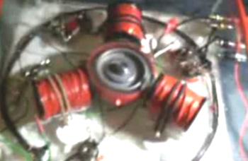 The Modified Computer Fan. Other more simple methods of getting this radiant energy charging of batteries are also available. One simple method is to skip most of the mechanical construction and use a slightly adapted synchronous fan. This method is shown by “Imhotep” in his instructional video which is located here. The original idea comes from John Bedini and the fan idea from Dr Peter Lindemann. The most common choice for the fan is a computer cooling fan - the larger the better. These fans usually have four windings connected like this:  To use these windings as both drive and pick-up coils, the fan is opened up by lifting the label covering the hub of the fan, removing the plastic clip holding the fan blades on the spindle and opening the casing to expose the coils. The wire post with two wires going to it then has one wire removed and a fourth post improvised by drilling a small hole and inserting a short length of wire from a resistor. The fourth wire end is then soldered to it to give this arrangement:  This produces two separate coil chains: 1 to 2 and 4 to 3. One can then be used as the drive coil and the other as the power pick-up coil which passes the very short high voltage pulses to the battery which is being charged. When opened up, the fan looks like this: 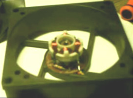 And the circuit arrangement is:  The fan is started by hand and then continues to spin, working as a fan as well as charging a battery. The current draw from the driving battery is very low and yet the radiant energy charging of the other battery (or battery bank) is not slow. Please remember that batteries which are to be used with this radiant energy, need to be charged and discharged many times before they become adapted to working with this new energy. When that has been accomplished, the battery capacity is much greater than specified on the label of the battery and the recharging time also becomes much shorter. The circuit is adjusted with the variable resistor, which changes the transistor drive current, which in turn, alters the speed of the fan. The variable resistor setting is adjusted very slowly to find the resonant spot where the input current drops to a minimum. At resonant point, the battery charging will be at it's maximum level. It should be stressed that this device and the relay charger shown below, are simple demonstration devices with small coils and to get serious charging, you need to use one of John Bedini's large-coil battery pulsing systems with a bank of lead-acid batteries being charged. A very neat build of an 80 mm computer fan conversion to a pulse charger built by Brian Heath is shown here: 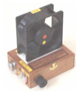 The Car Relay Charger. An even more simple charging method is also shown by “Imhotep” in another of his instructional videos at http://d1190995.domaincentral.com.au/page6.html. Here he adapts an ordinary 40 amp car relay, converting it from having a “normally open” contact, to operating with a “normally closed” contact. It is not necessary for you to do this as automotive relays with “normally closed” contacts are readily available and are not expensive. The relay is then wired up so that it powers itself through its own contacts. This causes a current to flow through the relay coil winding, operating the contact and opening it. This cuts off the current through the relay’s own coil, causing the contacts to close again and the process starts all over again. The repeated opening and closing of the relay contacts happens at the resonant frequency of the relay and this produces a buzzing noise. Actually, buzzers were originally made this way and they were used in much the same way as a doorbell would be used today. The circuit used is shown here:  As you can see, this very simple circuit uses only two components: one relay and one diode. The key feature is the fact that when the relay contacts open and current stops flowing through the relay coil, a very high voltage spike is generated across the relay coil. In transistor circuits which drive a relay, you will see a diode wired across the relay coil in order to short-circuit this high voltage at switch-off and stop the transistor getting destroyed by the excessively high voltage. In this circuit, no protection is needed for the relay. Any number of batteries can be charged at the same time. An ordinary 40 amp automotive relay like this: 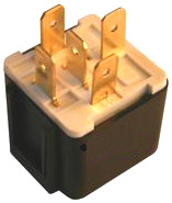 can have a “changeover” contact, which means that it has a “normally closed” contact and so can be used directly without any need to open or modify the relay itself. In this circuit, however, that reverse voltage is being used in a very productive way. These voltage spikes are very sharp, very short and have a very fast voltage rise. This is exactly what is needed to trigger an inflow of radiant energy from the local environment, into the battery. This battery charging current is not coming from the driving battery but is coming from the environment. The small current from the driving battery is just operating the relay as a buzzer. Please remember that at this time, we have no instrument which can directly measure the flow of radiant energy into the charging battery. The only reliable way of assessing the inflow is to see how long it takes to discharge the charged battery through a known load. My experience with using relays for battery charging indicates that you get a better result if 24 volts is used to drive the circuit and as vehicle relays don’t have that much of a coil winding, there is a considerable improvement if a large coil is connected across the relay coil or coils as shown here:  When using one of these relay charging systems you will find that quite a lot of noise is generated. This can be reduced quite easily with a little padding and it does have the advantage of indicating that the charging system is running correctly. The Self-charging Motor. A video shows an interesting home-built device which uses the motor out of an old video recorder, the bearing out of an old computer CD drive and pick-up coils made by removing the case and contacts from standard relays: 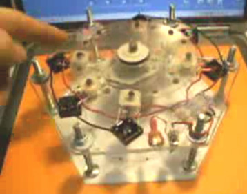 The construction is very straightforward with a simple, uncluttered, open layout: 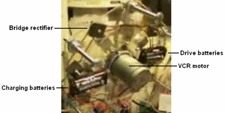 With this arrangement, one pair of AA-size NiCad batteries drives the motor, spinning the motor, moving its magnets rapidly past the ring of converted relays, producing charging DC current via the bridge rectifiers and that current is sufficient to keep the device running continuously. A comment made on the video is that if the ferrite magnets were replaced with neodymiums, then the charging voltage rises to around 70 volts. Unfortunately, the present rotor is too flexible and the neodymium magnets actually flex the rotor down towards the relay cores as they pass, so a more robust rotor is needed. The "Alexkor" battery-charging system is very effective, cheap and easy to build. It is a version of the system described in Fig. 22B on page 7 of this web page:  While this description has been around for years, it is part of a discussion on the principles of the operation of EMF magnetic fields and pulsing in coils. 'Alexkor' has developed a practical circuit which he says works very well. It can be constructed as a single unit as shown here:  Here, the coil is wound with 500 turns of 0.7 mm enamelled copper wire and the actual construction is compact:  And to get an idea of the performance, Alex uses a capacitor to see the size of the voltage spikes produced by the circuit:  This is the first step in the process as the same circuit can be used to drive many coils of this type. The resistor feeding the base of the transistor is about 500 ohms for the prototype, but using a 390 ohm resistor in series with a variable resistor of say, 1K, would allow a good standard resistor value to be selected for each transistor/coil pair:  As can be seen from the photographs, Alex uses preset resistors to adjust the settings to their optimum values. The simplicity of this circuit makes it very attractive as a construction project and using more than one coil should make for impressive performance figures. Alex says that the best results are achieved with just the one (1000V 10A) diode and not a diode bridge, which is borne out by the teaching comments on the above web site. One possible modification worth investigating as a test, would be the coil core arrangement which Richard Willis uses for his very impressive device described in chapter three. This would involve inserting a ferrite rod powered by two permanent magnets, into the coil:  and while the Willis arrangement shows the coil wound directly on the ferrite rod, the fact that there is an air gap between the coil and the ferrite rod should not be a problem. If you want to produce a resistor of 2.061K, then as it is not a standard value, it can be done by combining two or three standard resistors. In any case, as actual resistor values are not guaranteed to be exact, you would need to use an ohmmeter to measure the precise value if you want it to be exactly 2,016 ohms. A 1.8K resistor in series with a 220 ohm resistor is likely to be close. This is where the information at the start of chapter 12 comes into play. While it is not likely to be able to operate at frequencies as high as 35 KHz, a very good material for coil cores is the metal of masonry anchors or "sleeve anchors": 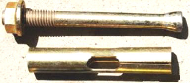 This metal is immune to rusting, easy to work and loses all magnetism as soon as the magnetic field is removed. You can confirm this for yourself by placing a permanent magnet on one end of the bolt or the tube and using the other end to pick up a steel screw. As soon as the permanent magnet is removed, the screw falls off as the metal does not retain any of the magnetism from the permanent magnet. These anchors are cheap and readily available from builder's supplies outlets, including those on the internet. It is unlikely that this material could operate at more than 1,000 Hz and the circuit above gains a lot of it's performance from the high speed, fast switching and very short "On" time duty cycle. If you use the bolt section of one of these anchors, the conical bump at the end of the shaft will have a delaying effect on the build-up and release of the magnetic field and so it might be advisable to either file it down gently by hand, or to cut off the conical section. There will always be eddy current losses in any solid metal core, but that does not stop them being very effective in operation. As with everything else, testing an actual device is the key to good performance and sound knowledge. The Ron Cole One-Battery Switch. The following circuit is unproven as far as I am aware, but it is an interesting idea. Also, I am not sure if the idea came from John Bedini or from Ron Cole. It has the potential advantage of being a battery charger which operates on its own driving battery. It may also be possible to operate it while it is powering a load. At this time, this is not a fully tested circuit, so please treat it as an idea for experimentation if you are so inclined. The idea is to use two capacitors which are charged up to the battery voltage and then suddenly connected together to apply twice the battery voltage to the battery. The idea is that the sudden pulse may be sharp enough to cause an inflow of radiant energy from the local environment. To be successful, that energy inflow has to be greater than the current draw of the circuit and the capacitors. The circuit is essentially like this:  Here, the pulser circuit is set to give short, very sharp pulses to drive the relay cleanly. The relay has two changeover contacts “A” and “B”. The operation is very simple. Initially, the capacitors “C1” and “C2” are charged up when the relay is in it’s unpowered state and no current is flowing through the relay coil:  As you can see, the “normally closed” relay contacts have each of the capacitors connected directly across the battery supply rails. This gives the circuit shown above on the right. When the relay is powered up, the situation changes very suddenly to give this arrangement:  Here, the two charged capacitors are disconnected from the opposite supply rails and connected together to form a combined voltage of, in the case of a 12 volt battery, 24 volts connected across the 12 volt battery. This will cause a sudden inflow of current into the battery. However, before practically any capacitor current has flowed, the relay is operated again, repeating the sequence. The Tesla Switch. The Tesla Switch is covered in more detail in Chapter 5, but it is worth mentioning it again here as it does perform battery charging. The similarity ends there, because the Tesla switch does the battery charging while the circuit is providing serious current into a load. Also, the Tesla switch uses only four batteries, and still is capable of driving a thirty horsepower motor, which is the equivalent of 22 kilowatts of electrical power.  The simple circuit shown here was used by testers of the Electrodyne Corp. over a period of three years using ordinary vehicle lead-acid batteries. During that time, the batteries were not only kept charged by the circuit, but the battery voltage climbed to as much as 36 volts, without any damage to the batteries. If the voltage on a battery under load actually increases, it is reasonable to assume that the battery is receiving more power than that delivered to the load (a load is a motor, a pump, a fan, lights, or any other electrical equipment). As this is so, and the circuit is not connected to any visible outside source of energy, it will be realised that there has to be an outside source of energy which is not visible. If the circuit is provided with powerful enough components, it is perfectly capable of powering an electric car at high speeds, as has been demonstrated by Ronald Brandt. This indicates that the invisible source of outside energy is capable of supplying serious amounts of additional power. It should also be remembered that a lead-acid battery does not normally return anything like 100% of the electrical energy fed into it during charging, so the outside source of energy is providing additional current to the batteries as well as to the load. So, how does this circuit manage to do this? Well, it does it in exactly the same way as the battery pulse-charging circuits in that it generates a very sharply rising voltage waveform when it switches from its State 1 to its State 2 (as shown in detail earlier). This very rapid switching unbalances the local quantum energy field, causing major flows of energy, some of which enters this circuit and powers both the circuit and the load. Although it does use four batteries, and the batteries do get charged through the generation of sharp pulses, this is not a circuit which charges massive battery banks so that they can power a load at some later time. Patrick Kelly engpjk@yahoo.co.uk http://www.free-energy-info.co.uk/ |