

Additional comment :
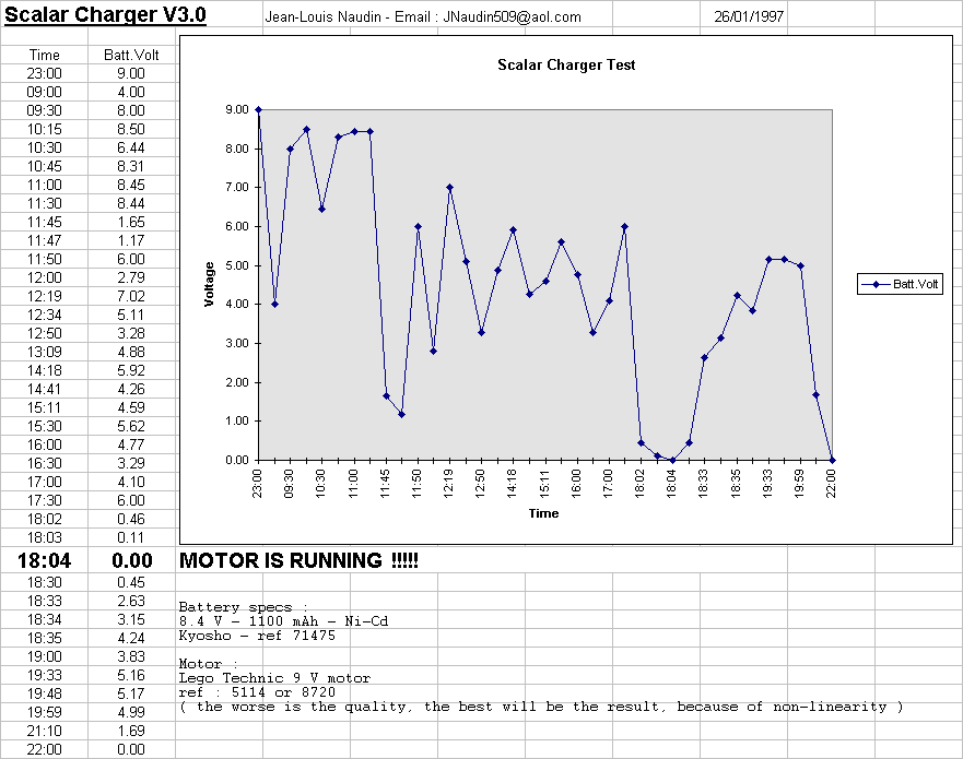
The most strange event is that after 19 hours of running time, the battery voltage drop to 0 volts, and the motor continued to run ( !!! ?? !!! ). It seemed that the condensators could maintained power to supply motor after this first deadline. You could see on my report that the charge of battery restart after, for new 4 hours ( strange and curious event ?? ). I couldn't explain today what happened, but it's reality. I don't know if it is the good way for overunity, I have the feeling that it isn't......
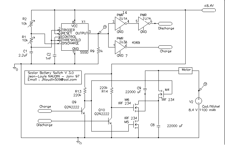
The clock frequency is 25 Hz ( T=40ms) with cyclic ratio of 50%.
You have the specs of some MosFet bellow :
IRF820 ( MOS-N-FET-e V-MOS, 500V, 2.5A, 50W, <3ohm(1.5A) )
IRF234 ( MOS-N-FET-e V-MOS, 250V, 8.1A, 75W, <0.45ohm(4.1A)
BUZ11  ( MOS-N-FET-e V-MOS,  50V, 30A,  75W, <0.04ohm(19A)
but you can see in these characteristics that the IRF234 have a RDS of 0.45ohm Vs 3 ohm for the IRF820. Better RDS is low better the result because joules effect losses must be minimized.
The main problem is the stability of the battery charge, I think that this device must be used as a demonstrator purpose only but not in real operational use (power supply). Because the battery don't support the high peak of voltage and if the device is not properly tuned it may destroy the battery ( lost of its memory effect ). If the charger is correctly tuned it run as a scalar charger but it is difficult to tune correctly for long working time.
Return to Quantum Electrodynamic page