rexresearch.com
Edward V. GRAY
Electro-Magnetic
Association (EMA) Motor
(Pulsed Capacitance Discharge
Engine)
Tom Valentine: The
National Tattler (1 July, 1973, page 5): "Man Creates Engine That Consumes
No Fuel; Invention Could Change History By 1984"
Tom Valentine: The
National Tattler (January 23, 1974): "Two Inventors Work To Devise
Fuelless Car"
Tom Valentine: The
National Tattler (1 July, 1973): "Gasless Auto Gets $6-Million
Backing"
Progress Bulletin
(Pomona, CA) July 7, 1975: "Either Saint or Sinner ~ Auto Motor Inventor Just
Fueling Around?"
Tom Valentine: The
National Tattler (March 1974): "Inventor of the World's First No-Fuel
Engine is Suppressed by L.A.'s District Attorney"
Tom Valentine: The
National Tattler (March 1974): "Threat of Arrest Spurs Tattler
Reporter"
Jack Scagnetti: Probe
The Unknown (June 1973): "The Engine That Runs Itself"
Tom Valentine:
NewsReal (Date Unknown): "EMS --- Electronic Power That Could Change
The World's Economic Power Picture"
EVGray Enerprises: "Power Plant of the Future"
Edwin V. Gray:
US Patent # 3,890,548 --- Pulsed Capacitor
Discharge Electric Engine
E. Gray: US Patent # 4,595,975 --- Efficient Power
Supply Suitable for Inductive Loads
E. Gray: US Patent # 4,661,747 --- Efficient
Electrical Conversion Switching Tube Suitable for Inductive
Loads
Peter A. Lindemann: "The
Free Energy Secrets of Cold Electricity"
E. Gray: US Patent Application: "Regenerative
Energy Recovery System, e.g., for Electromagnetic Propulsion" ( 10
April 1980 )
The National Tattler (1 July, 1973, page 5)
"Man Creates Engine That Consumes No Fuel; Invention Could Change History By 1984"
by Tom Valentine
A California inventor has found a way to create limitless electric power without using up fuel --- potentially the greatest discovery in the history of mankind.
Edwin Gray Sr., 48, has fashioned working devices that could:
Power every auto, train, truck, boat and plane that moves in this land --- perpetually.
Warm, cool and service every American home --- without erecting a single transmission line.
Feed limitless energy into the nation's mighty industrial system --- forever.
And do it all without creating a single iota of pollution.
Already, the jovial, self-educated Gray is forcing scientists to uproot their most cherished beliefs about the nature of electromagnetism.
Eventually, his discovery will transform the economic base upon which the society of the entire planet has rested up to this point.
Despite the ever-present danger from the petroleum and other power giants who face business extinction within the decade because of his invention, Gray and his associates in EvGray Enterprises have demonstrated its worth publicly --- an act requiring great courage.
And Tattler is proud to report for the first time in America the complete nature of gray's astounding system.
Displaying the kind of open honesty that made America great, Gray and his partners stress the fact that they want the whole world to benefit from their new technology.
"I won't allow it to be bought up and buried by big money interests", Gray told Tattler during the exclusive demonstration.
"I tried for 10 years to get American interests to pay some attention, but I've been tossed out of more places than most people ever think of going into."
Neither government agencies nor private enterprise would listen to Gray, so he turned in frustration to foreign interests. The innovative Japanese were eager to listen.
"As soon as word got out that the Japanese were interested in what we're doing, the Americans started flocking around."
Today, the small shop facility in Van Nuys is crawling with visitors from every segment of US industry and finance.
"The big money boys from Wall Street started coming around", Gray said with a touch of defiance in his tone.
"A bunch of them came in and suggested I file bankruptcy and get rid of all my backers and friends. Then they talked about giving me 20 million shares of a new corporation at $25 a share."
Gray was being offered a deal worth more than $4 billion --- on paper.
"That sure sounded rich, but I know darn well they would have fixed it up to sell that corporation off somewhere for a dollar and leave me holding 20 million shares of nothing."
The key men at EvGray include Richard B. Hackenberger, an electronics engineer who formerly worked for Sony and Sylvania corporations and the US Navy; and Fritz Lens, a former Volkswagen mechanic who knows nearly as much about the fantastic electrical system as Gray.
All the corporate officers agreed that they are determined to get around the money roadblocks and bestow the discovery upon the world.
Tattler was given a thorough demonstration of Gray's "impossible-but-true" methods for using electricity.
The first demonstration proved that Gray uses a totally different form of electrical current --- a powerful, but "cold" form of the energy.
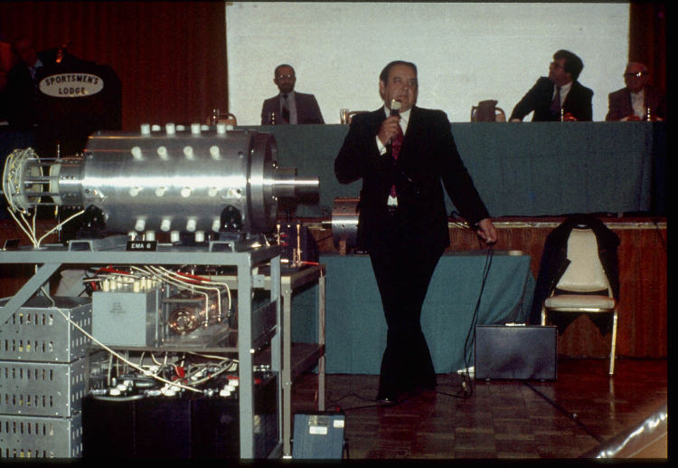
A 6-volt car battery rested on a table. Lead wires ran from the battery to a series of capacitors which are the key to Gray's discovery. The complete system was wired to two electromagnets, each weighing a pound and a quarter.
"Now, if you tried to charge those two magnets with juice form that battery and make them do what I'm going to make them do, you would drain the battery in 30 minutes and the magnets would get extremely hot", Gray explained.
"I want you to watch what happens."
As Lens activated the battery, a voltmeter gradually rose to 3,000 volts, At that point, Gray closed a switch and there was a loud popping sound. The top magnet hurled into the air with tremendous force and was caught by Hackenberger. A terrific jolt of electricity had propelled the top magnet more than two feet into the air --- but the magnet remained cold.
"The amazing thing", Hackenberger said, "is that only 1% of the energy was used --- 99% went back into the battery."
Gray explained, "The battery can last for a long time, because most of the energy returns to it. The secret to this is in the capacitors and in being able to split the positive."
When Gray said "split the positive", the faces of two knowledgeable physicists screwed up in bewilderment. Normally, electricity consists of positive and negative particles. But Gray's system is capable of using one or the other separately and effectively.
"He means we have to rewrite the physics textbooks", Hackenberger grinned. It has been the engineer's job in recent months to formulate gray's system and put it into writing.
"That's not an easy job because this system actually defies everything I've ever learned."
Gray said, "I never had no schooling in electronics or physics, so nobody told me it was impossible."
The "impossible" part of the demonstration was the lack of heat generated in the magnet. Heat is one of the biggest problems faced by electrical technology. Also "impossible" is the fact that only the "positive" nature of the energy was used.
"This thing is in its infancy", Gray explained. "When the full potential of American technology starts working with it, the results will astound everyone."
A further proof that he has an unusual source of power with unlimited potential was demonstrated next.
"We've been popping those magnets apart for the past 18 months with the same battery and it's still got a full charge. Now I want you to watch this "
Gray showed this Tattler reporter a small 15-amp motorcycle battery. It was hooked up to a pair of his capacitors which in turn were hooked up to a panel of outlets.
He flicked a switch and the tiny battery sent a charge into the capacitors. He then plugged in six 15-watt electric bulbs on individual cords --- and a 110-volt portable television set and two radios. The bulbs burned brightly, the television played, and both radios blared --- and yet, the small battery was not discharging.
"You couldn't get all this current out of that battery under ordinary circumstances", Gray said.
"This is the most amazing thing I've ever seen!" exclaimed C.V. Wood Jr, president of the McCulloch Oil Corporation, who was also present at the demonstration. He began looking for hidden outlets from the wall.
"May I prove it doesn't come from any wall plug?" Gray offered.
A 40-watt light bulb screwed into an ordinary extension socket was plugged into the panel powered by gray's system. The bulb lit, then Gray dropped it into a cylinder filled with water.
"What would be happening if this was getting ordinary power right now?" Gray asked, as he stuck his hand in the water with the glowing light bulb.
"You'd be electrocuted and that thing would be popping and sputtering until the fuses blew", Wood replied.
This reporter then put his finger into the water with the light --- no shock.
"Gentlemen, this is a new manifestation of electricity", Hackenberger said.
The engineer told the astounded onlookers that no laws of physics were being violated, but a new application of electricity has been discovered and put to work.
Gray, one of 14 children, comes from Washington DC. As a small boy, he was fascinated by electricity, magnets, and gadgets in general.
"I really got excited about electricity when they tested the first radar across the Potomac in 1936. I was 11 years old then and visions of buck Rogers danced in my head."
He learned about radar during his World War II hitch in the Navy and "I've been messing around with coils and capacitors ever since".
He learned to "split the positive" in 1958 and spent the next dozen years finding the funds to put his discovery to work.
Any abbreviated explanation of Gray's system is an over-simplification of the technical aspects of this tremendous breakthrough, but some of the best minds in the US are now working with Gray to further improve his discovery.
Gray held the 40-watt bulb up out of the water and said: " You know, to light this bulb takes millions of dollars in power plant facilities, transmission lines, and circuitry. With my capacitors, I can provide power to any home for a couple hundred dollars."
The economic impact of that statement is beyond the imagination --- not to mention the ecology and anti-pollution benefits.
Tom Valentine & Edwin Gray: Demonstration of "Cold Electricity"~
The National Tattler (January 23, 1974)
"Two Inventors Work To Devise Fuelless Car"
by Tom Valentine
Merging an electromagnetic motor with an all-plastic body and chassis, two pioneering inventors will put the first fuelless automobile into production and on sale this year.
The revolutionary machine is being called "that car of the future" for Americans today.
"We have the answer to the energy crisis", declared Edwin Gray, the Van Nuys, CA inventor who revolutionized the use of electricity by producing an electromagnetic motor using an ordinary auto battery that does not wear down in a few short miles.
"Our system can eventually solve the world's fuel and pollution problems", Gray told Tattler.
Paul M. Lewis, inventor of the "Fascination", an ultra-modern, "three-point road contact", all-plastic auto. His car of the future lists a number of engineering advantages over today's models, and the EMA motor will slowly replace internal combustion engines
Although it looks like a "three-wheeled" car, the Fascination actually has four wheels. The two front wheels are set close together. It is similar to the front wheels of an aircraft. Thus the name for Lewis' corporation --- Highway Aircraft Corp.
The 77-year-old inventor told Tattler, "Mr. Gray has promised delivery of his EMA motor by March of 1974 and we'll get our car on the road shortly afterwards."
Lewis, a veteran of many hassles with the auto-oil monopoly, was finally forcing his way to the marketplace with an all-new auto design when he heard about the EMA motor.
"We had an advantage over standard cars even with our Renault engine. But, with this motor, the big boys don't have a chance unless they get up to date," the fiery inventor told Tattler. "I've battled the industry tooth and nail for years now, and now we're coming on strong."
In 1936, Lewis designed a three-wheeled car that looked a lot like the present Volkswagen bug. He called it the "Airmobile", and his original model is still on display at Harrah's auto Museum in Reno, NV.
Though he hid not know what Dr. Ferdinand Porsche was doing in Germany, the Lewis Airmobile was amazingly similar to the popular VW beetle.
Both vehicles were low cost, simplistic in design, used horizontal opposed four-cylinder air-cooled engines, transaxles, independent suspension systems and unitized body construction.
When World War II came along, it sent VW soaring in Germany, but killed the Airmobile. Porsche fit into the German establishment, but Lewis was a "crackpot" inventor and a pain in the neck to the economic status quo.
The VW beetle's popularity proves that Lewis' original idea was valid and worthy, despite the laughter from Detroit.
The Airmobile was driven out of business in the late 1930s by the Securities and Exchange Commission and the U.S. Postal Department, who have been called bureaucratic flunkies for the oil-auto monopoly.
"I was harassed for two years and they refused to let me sell stock in my company on the pretense they were investigating possible wrongdoing", Lewis said. "After I was beaten down, they sent representatives to tell me they found nothing wrong and I could sell stock. A man can't make a dead horse walk."
After losing the Airmobile, despite driving it through 26 states for more than 45,000 miles without a repair, Lewis went from Denver to Los Angeles, where he continued inventing.
His inventions made him financially solvent and he charged back into the auto business.
He planned to use his own "boilerless" steam engine in Fascination until the EMA motor came along.
A model of Ed Gray's motor is on display at Lewis' Highway Aircraft Corp., headquarters in Sidney, NE.
"We will eventually have stock to sell, but at this time we simply want the public to keep abreast of our progress", Lewis told Tattler.
Although still in the embryo stage, the merger of the two inventions promises to keep America in the technological forefront of the world.
The first prototype car cost Lewis more than $200,000 to build and the first prototype EMA motor ran close to $1 million to build.
"We will eventually tool up for mass production and bring the costs down considerably", Lewis said. "But the first 100,000 or so fascination cars with the EMA motor will cost the public about $2 per pound. Today's cars cost about $1 per pound, but we're almost twice as light."
The buying public will pay an estimated $5,000 for the Fascination with the EMA motor.
Although the Fascination will be priced with moderate cars and more expensive than economy cars, the savings on fuel and repair costs quadruple its value.
The body of Fascination will be made of Royalex, a tough rubber-like Uniroyal product.
To insure that his radical design will be practical and not only meet but surpass all safety standards, Lewis has contracted with two of the best automobile engineers in the world.
Visioneering, Inc. (Fraser, MI) is concentrating on the Fascination in order to insure it does everything Lewis claimed.
Richard Hackenberger, the electronics engineering expert hired by Gray to put his motor to work on a practical basis, explained how the new car will operate:
"Because we are not taking current directly from the batteries, but rather are supplementing the static charge which operates the system, we are getting fantastic efficiency.
"Of course, further research and development will eventually allow a motorist to drive across the nation without recharging his batteries, but we estimate a family could drive 500 miles at highway speeds without recharging."
Hackenberger said the 500-mile estimate is a "conservative" one and is applicable to a car using air-conditioning or heating and radio.
"Just driving around town, the EMA will last a lot longer without recharging", he said.
The engine will run in any temperature and there is no noise, no cooling system, and no exhaust fumes.
"The battery will go to work when the key is turned on and the light on the dash will glow while the starter motor builds the rotor up to speed. The light is used instead of a tachometer and it will only take a few seconds for the motor to build up and be ready to go."
Hackenberger was quick to explain, "We do not have perpetual motion here. We have an electrostatic generating system and a capacitor bank doing some very efficient work. The principle is based on a modification of Ohm's Law."
The power for the motor is generated by magnetic repulsion. Engineers have tested the motor and it develops 100 horsepower at the brake.
"This means we are as powerful as any standard internal combustion car on the road today. The inefficiency of the internal combustion engine is the reason", he said.
The National Tattler (1 July, 1973) ~
"Gasless Auto Gets $6-Million Backing"
by Tom Valentine
The man who first told the world through a Tattler article that he had invented a no-fuel engine capable of providing electricity at half today's cost has received more than $6 million to develop his machine.
"We're finally out of the woods", inventor Edwin Gray, president of EvGray Enterprises (Van Nuys, CA), told Tattler.
"We've been struggling against the big business monopoly (against the marketing of new types of power plants) for years in this country, but finally made it --- and we did it without going to foreigners."
Gray's revolutionary ideas in power production were first made public in this periodical last summer. The inventor has received additional funds to develop an automobile motor for an all-new plastic car to be called "Fascination".
He plans to build a battery substation to supply 100 megawatts of electricity at peak periods while expending only 40 kilowatts doing so, using cobalt batteries and electromagnetic association motors, which he developed.
This goal has been disputed by many "experts", who claim Gray and his company may be perpetrating some kind of hoax.
Gray's electromagnetic association (EMA) motor is not perpetual motion or any mystery, he stressed, but rather a unique blending of three known forces to make energy.
"Using static electricity isn't new, neither is recycling power or activating electromagnets, but Ed Gray simply became the first to put all three together with the right combination", Richard Hackenberger, his aide, told Tattler.
Whether it's driving a car or generating power, the EMA system works the same.
The motor draws small amounts of direct current from a battery and blends it with static electricity to make the static "work".
The static charge then activates the electromagnets, the engineer explained.
Tests conducted this past September by Crosby Research Institute (Beverly Hills, CA) showed the original EMA prototype motor had a "measured overall system efficiency exceeding 99%".
Crosby Engineering director J. A. Maize conducted the intensive testing on behalf of Pan World Enterprises Company, Ltd., a Japanese conglomerate.
Maize operated the motor into a 10-horsepower dynamometer load at 1,100 rpm, a power output of 7,460 watts.
But the batteries used in the test were only capable of 5,454 watts per hour. Therefore, the motor was making its own electricity while it worked --- and using absolutely no fuel in the process.
"The system will operate continuously for 203 hours at 10 horsepower and 1,100 rpm without recharge since the total battery power consumed is only 26.8 watts per hour", Maize said.
"Recycling of the batteries during non-operational periods would permit continuous system operation until the end of battery life."
Since those tests, however, the EvGray people have further improved their system.
Funds to develop the generating plant have been provided by a trio of wealthy US geologists who made fortunes in oil exploration, but now feel a new source of energy is mandatory for the world, Gray told Tattler.
"The men who financed this project don't want their names released to the public", he said. "They're seeking electricity, not publicity."
When Gray and "Fascination" car designer Paul Lewis announced plans to have the fuelless car on the road by the end of 1974, he already had improved the motor to the point where he could drive the car at normal speeds for more than 500 miles between rechargings.
"But since we are estimating, we are being ultra-conservative", Hackenberger insisted. "We now plan to have a prototype car on the test track by the end of summer."
Original plans called for the car to be in prototype earlier, "but lawyers, not our system, held us up", Gray added.
Gray now is beginning negotiations with foreign groups after refusing the temptation for years while waiting for some developments in the US.
"The Italian government is very interested", Gray told Tattler. "We were told by one representative that they wanted to develop this source of power quickly because they never want to look at another Arab as long as they live."
Progress Bulletin (Pomona, CA) July 7, 1975 ~
"Either Saint or Sinner ~ Auto Motor Inventor Just Fueling Around?"
Los Angeles (AP) ~ Edwin Gray, a self-educated inventor, says he has designed a car motor that needs no fuel. Hundreds of investors have put their money on it.
But local authorities have charged him with bilking his believers out of thousands of dollars. A specialist in energy engineering saw the prototype motor and said if it worked, "it would violate all the laws of physics"
In the eyes of Gray's supporters, it is a case of a small-time inventor being harassed because he is on the trail of a revolutionary idea that challenges the auto establishment.
If allowed to develop his invention, Gray said, "This motor will probably replace most motor power in the very near future."
Claims for the device have varied over the past four years, according to the Los Angeles County district attorney's office, but essentially it has been described as an electromagnetic motor" that is started by a set of batteries, then runs virtually on its own and puts energy back into the batteries --- enough so that they need charging only infrequently.
"If it did what he says it would violate all the laws of physics", said Donald Cronin, a staff scientist at TRW Systems, Inc., who watched a test of the motor about a year ago.
"It ran for about 10 seconds and then everything blew", he said. "A group of scientists from a big research firm in Japan had come with an elaborate amount of equipment --- gauges, instruments, and TV cameras --- and were ready to sign a letter of intent. After the test, they packed it all up and went back to Japan."
Gray, 50, says he has been toying with the idea for such an engine since he was 7 years old. He is almost boastful about his lack of scientific training.
"The technical people tell me that if I had a technical background I wouldn't have come up with a motor like this", he says.
Gray began selling shares in his invention in 1971 and attracted some 800 shareholders. Last July investigators from the district attorney's office seized the prototype engine, plans, drawings and bookkeeping records. It was not until May that charges were filed against gray --- one count of conspiracy to commit grand theft, eight counts of grand theft, and three counts of a securities violation.
Gray's attorneys' cite the 10-month delay as one sign of harassment. A national tabloid newspaper attacked the D.A.'s office for its "behind-the-scenes suppression of one man's effort to help mankind".
This kind of talk frustrates the investigators, who see themselves as acting to protect lay investors who aren't able to distinguish a technically complicated fraud from a valid research effort.
Edwin Gray must be persuasive, though: two investigators from the D.A.'s office "went down to see and got hustled themselves --- they invested money of their own for a while, but later got it back", said Deputy D.A. Mitchell Harris.
As to why the case has taken so long to prosecute, authorities say that, in the first place, it has been hard to find investors willing to press charges.
The D.A.'s office also points out that the investigators were busy with other cases they considered more pressing, and this kept them form wrapping up the gray investigation.
The National Tattler (March 1974) ~
"Inventor of the World's First No-Fuel Engine is Suppressed by L.A.'s District Attorney"
by Tom Valentine
Editor's Note: On July 1, 1973, Tattler published a story announcing the invention of a remarkable "fuelless engine" capable of powering an automobile. The engine, invented by Ed Gray and named the EMS motor, functioned on an electromagnetic principle that allowed it to regenerate its own power.
At the time, Tattler predicted the Gray engine would revolutionize the auto industry. We also published Gray's announcement to have automobiles containing the engine in production an available to the public by the end of 1974. That obviously has not happened yet, and for a very good reason.
For the past seven months, Gray has been the victim of an incredible campaign of obvious harassment by the Los Angeles District Attorney's office. This harassment appears to be yet another chapter in a long history of attempts to suppress any automobile invention that might disrupt the status quo for auto manufacturing as established by Detroit's car-making giants.
Tattler was warned not to print this story until the issue was settled in court. We are printing it because the public has a right to know what is happening and because it has become obvious that the district attorney has no intention of seeking a quick decision in the case. In this exclusive report, Articles Editor Tom Valentine reveals the sordid, behind-the-scenes suppression of one man's effort to help mankind.
"Threat of Arrest Spurs Tattler Reporter"
At one point during his investigation of the Ed Gray EMS motor case, Tattler Articles Editor Tom Valentine was threatened with arrest if he pursued the matter.
The threat came from Ran Novell, an investigator with the Los Angeles District Attorney's office.
When Valentine telephoned the district attorney's office to inquire why the DA had kept the gray case pending five months without bringing formal charges, Novell snapped back:
"I'm advising you of your rights. You have the right to remain silent because anything you say may be used against you in a court of law."
"I don't have anything to say. I'm simply trying to ask questions", replied Valentine.
"Well, you might be indicted as a co-conspirator in this case", said Novell.
"You've got to be kidding", said Valentine.
Later, Valentine expressed his opinion that the threat was nothing more than an attempt to"scare me away from the case".
"But if that was what he was trying to do he couldn't have picked a worse tactic. All he succeeded in doing was making me resolve to get to the bottom of this", said Valentine.
The effort of Ed Gray to produce a fuelless automobile engine that could greatly benefit mankind has been blocked by the Los Angeles District Attorney's Office.
Gray is the inventor of the EMS motor --- a remarkable electromagnetic engine that regenerates its own power, thus eliminating the need for liquid fuel.
Gray had intended to have his motor in production and available to the general public by the end of 1974. However, a series of confrontations with the L.A. District Attorney's office has completely stymied his efforts.
Gray's problems began last July 22, when L.A. authorities raided his plant in Van Nuys, CA. Virtually everything in the building was confiscated --- including his working prototype motor.
Seven months later, not a single charge has been brought against Gray. Yet, the L.A. District Attorney's office still has his records and engine models.
The Van Nuys raid is only the latest incident in a strange pattern of "non-arrests" of automotive inventors that dates back more than half a century.
In a continuing investigation of this phenomenon, Tattler has documented dozens of cases in which inventors came up with "a better idea" for an automobile engine, only to be harassed into tragic situations ranging from bankruptcy to suicide.
One example was the invention of the Lewis automobile more than 40 years ago.
In 1933, Paul Lewis invented a three-wheeled car powered by an air-cooled engine. Called the "Airmobile", Lewis' product proved itself in road tests.
But when he began selling stock in his company in order to obtain capital to mass-produce the vehicle, the Securities and Exchange Commission stopped him.
For years the SEC kept Lewis "under investigation" without bringing any formal charges. Finally, he was harassed into bankruptcy.
"Once I was bankrupt the SEC dropped its investigation and told me I was clear to continue", Lewis recalled during a recent interview with Tattler. "All I could do was swear at them and ask them if they knew any way I could make a dead horse walk."
Today Lewis' "Airmobile" can be seen in a museum at Harrah's Club in Reno, NV.
Ironically, his "better idea" was not totally suppressed.
In Germany during the 1930s away from the influence of Detroit's auto giants, an automobile was developed using the air-cooled engine principal first advanced by Lewis. Today, that car is called the Volkswagen.
Yet another example of such suppression is found in the history of the John Robert Fish carburetors.
Fish invented a carburetor that double the gas mileage of Detroit's standard carburetors. When Detroit snubbed his invention, Fish tried selling his invention through the mails to do-it-yourself mechanics. He was growing successful when Post Office Department agents swooped down on him for "investigation of fraud".
Several years later he was exonerated of any charges. But not until the mails to and from his business were stopped during a lengthy "investigation". He was wiped out financially.
A modern case is that of the LaForce brothers, presently locked in a controversy with the Environmental Protection Agency, which yet another branch of our huge federal bureaucracy.
The LaForce brothers are outstanding mechanics and automotive engineers from Vermont who have designed and built an improved auto engine.
The LaForce engine was tested by the EPA last fall and government spokesmen announced they were impressed. It looked like a small time inventor had finally broken through the bureaucratic curtain.
Hardly a week passed after the impressive EPA tests when it was announced that the LaForce engine, though more efficient regarding mileage, was more polluting.
Ed LaForce told Tattler:
"That's a crock of you know what! I don't know what their motive is, but we conducted very thorough tests before going to the EPA."
The LaForce brothers are not barnyard operators; they own and operate extremely sophisticated equipment and they know what their engine can do.
Like Ed Gray's case, the LaForce controversy is just beginning.
On July 1, 1973, Tattler exclusively reported Ed Gray's discovery. Using electricity, he had found a way to drive a car without fuel, without pollution, and without noise.
The motor can be used to generate enough power to drive a car while recharging its own batteries --- providing practically perpetual power with super-efficiency.
On January 27, 1974, Tattler followed up with the story of how Gray and Paul Lewis were planning to put the EMS motor in the "Fascination" auto body designed by Lewis.
At that time, Gray said his system would need two banks of batteries and recharging would be accomplished simply because batteries could not take the charge rapidly enough.
Lewis and Gray could not get together financially and their plans changed.
Gray's attorney, Joel Ward, filled Tattler in on the details since the July 22 raid.
"Despite the action by the D.A.'s office, I am unaware of any of the 800 stockholders in EvGray Enterprises demanding their money back.
"I am aware that some of the stockholders have offered more money, which is certainly indicative of their confidence in gray's inventions."
Ward said that the company is in the process of thoroughly testing and evaluating a new prototype EMS motor.
"It is apparent that the academic scientists have taken issue with Ed Gray's layman's language", Ward said.
"Here's an inventor with only a high school education telling scientists that he can do something totally new to them, and saying so in language they cannot accept.
We are in the process of fully explaining the new concepts in scientific terms", Ward added.
The attorney stressed that the US Patent office has notified him that every claim for the Gray motor has been accepted and the patent will therefore be issued.
"This means they accept the novelty of his motor. Now we are testing the prototype to determine what it's optimum capabilities are."
Ward said that separate patents will be filed on Gray's innovative energy process.
Ward said the company has not wanted additional trouble, and therefore they have maintained a low key approach to the D.A.'s actions.
Ward added: "I'm not going to discuss what we night do at this time. From a legal standpoint it might not be wise."
Many people close to the controversy have wondered aloud why Gray doesn't sue the D.A. for the apparent harassment.
Ward refused to comment on a possible suit, but Tattler learned that no suit can be field until the case is closed. As things stand it is an "ongoing" investigation.
The investigator in charge, Ran Novell, told Tattler that, "We're going to charge Gray with grand theft for taking money under fraudulent pretenses. His motor doesn't do what he claims. All he has is a starter motor run by some batteries". However, Novell also admitted that no one in the D.A.'s office had tested the motor --- or even started it.
Since Tattler has been diligent in checking Gray's claims before publishing the first story, such a charge came as a surprise. A number of scientists pronounced the engine sound and workable before the initial story was printed.
Novell said that the original search warrant was based on a complaint by a former, and apparently disgruntled, employee.
The D.A.'s investigator, who is not an attorney, said there were also earlier complaints about stock sales.
As of this writing the charges are still "pending" and nothing has been resolved.
Normally, in cases of invention fraud, stockholders clamor for their money back and the inventor declares bankruptcy.
"I know a lot of people want us to get going and bring this invention out right now", Gray told Tattler, "and we're doing everything we can."
Novell told Tattler: "Look, if this thing had any possibility I'd be the first to promote it."
Tattler learned that Novell's sincerity may be questionable. The investigator had every opportunity to get all the facts in advance of the raid.
"I wrote the D.A.'s office last April when I first heard of the investigation and stated our willingness to cooperate", Ward said.
"My letter was ignored and they raided the facility. Then, and this is unheard of, after the raid I mad another offer to cooperate, which was also ignored."
Ward said that he submitted written expert opinion to Novell's office in the belief that Novell would exchange expert opinions.
"They have our expert's opinion in writing, but I'm still waiting for theirs", Ward said.
Tattler has learned from a source within the D.A.'s office that it is general knowledge that Novell is "persecuting" rather than "prosecuting" the case.
Probe The Unknown (June 1973) ~
"The Engine That Runs Itself"
by Jack Scagnetti
Newspaper Headlines from January, 1973: "Rationing in Effect as Winter Catches US Short of Fuel ~ Fuel Shortage May Curtail Rail Service ~ Smog-Proofed Autos Choking on Own Fumes ~ US May Approve Gasoline Rationing ~ Pace Picks up in Quest for Clean Engines"
Catastrophic problems, aren't they? Not only are we taking more out of the earth than the earth has to give, but we're also using what we take to ruin the air above.
Sitting in a small laboratory in Van Nuys, California, is a curious creation which, based on the merits of dynamometer tests and other rigid trials, claims to be the solution. It's called the EMA (Electro-Magnetic Association) motor and, in technical jargon, is described as "digital-pulsed, "time-phased", and "servo-controlled". Developed by EvGray Enterprises, an independent research and development firm, the unique engine runs on the principle of electromagnetic transformation.
In terms more meaningful to the layman, the EMA motor requires no fossil fuel, recycles its own energy, creates no waste, and is extremely quiet. Its size, weight and horsepower ratios are comparable to motors and turbines now in use.
The EMA's only external power source consists of four 6-volt batteries which never need recharging and which have the same life expectancy as the standard automobile battery. EvGray claims the motor duplicates the power and torque characteristics of internal combustion engines of similar size and weight, and the Federal and State Air Resources Board has granted the inventors a permit to further prove this claim by installing the EMA in test vehicles.
Edwin Gray, Sr, president of EvGray, predicts production costs of the EMA will be comparable to present motors and maintenance costs will be far less, "The EMA motor promises to make the world a cleaner place in which to live", says Gray, who has spent 12 years developing the engine. "Perfection of the EMA motor as a generating source could means the availability of inexpensive power to underdeveloped nations."
EvGray expects the EMA motor --- when tailored for specific applications --- to become a desired replacement for virtually all power systems now in use
Lightning & "Energy Spikes" ~
Gray describes the operation of his EMA motor as "similar to recreating lightning". He says the engineering and scientific world has known this recreation is possible but hasn't known how to do it. "When lightning hits the ground, causing a 10-million volt buildup, where does the energy come from to make it from a static charge to a lethal charge? Nobody really knows."
Richard B. Hackenberger, Sr., vice-president in engineering for EvGray, explains how the EMA system operates" "Power from the high-voltage section is put through a system of electrical circuitry to produce a series of high-voltage 'energy spikes'. The spikes are transferred to a small control unit, which in turn operates the major motor unit. The control unit, acting in a manner similar to that of a distributor in an internal combustion engine, regulates the spikes, determines their polarity (whether they be north or south) and directs their power to selected electromagnets in the main unit. While this occurs, the recycle/regeneration system is recharging the batteries with 60 to 120-amp pulses. The electromagnets are located on both the rotor and stator of the large motor. Attraction and repulsion between the two sets of magnets causes the motor to operate and generate horsepower. Once in motion, the motor recharges the batteries as a result of the recycle/regeneration system. To prevent condensation in the main cylinder, a half-pound of air pressure has to be maintained. Air is routed through the programmer for functional purposes. When the ambient temperature is 90 degrees, the motor operates at 170 degrees."
In short, the principle of the engine is to create electricity and recycle energy by the factor that every time magnets are energized off the peak of transients, a charge goes back into the battery. It's not a constant charge, but a pulse charge of 60 amps or better; thus, the battery must be of high quality. The batteries for the EMA motor are furnished by McCulloch Electronic Corporation of Los Angeles. After extensive research and testing, EvGray chose the model 110-75 Energy Center, which is said to produce maximum power for its weight and volume over an exceptionally long life span. This is achieved partly by use of an ultra-lightweight plastic case that minimizes dead weight (energy-storing components comprise more than 90% of the battery's weight). Features of the battery include extra-large plates separated by indestructible glass-rubber separators and a specially formulated lead oxide composition. Two of the 6-volt batteries are used for operation, while the other two serve as a reservoir. Mallory Electric Corporation of Carson City, NV, has also made a major contribution toward the design of the electronic pulsing system.
Long Range & Powerful ~
Electric-powered vehicles are not new, of course, but the poor energy-storage factor of batteries and their heavy, large size have thus far made them impractical for use in any vehicles requiring a long-range capacity. This drawback has restricted the market for electric power to small limited-performance vehicles. The maximum range of these vehicles when driven at 40 mph has been approximately 150 miles. Range is affected by the number of starts and stops, grades traversed, and acceleration demands.
The EMA motor needs only to run at 500 rpm for the normal recharging system to work. In fact, its recharging capabilities are such that the EvGray's next version of the engine won't have an alternator or air pump. The air pump will be replaced by blades on the rotor.
"The idea of a self-sustaining electric motor", says Gray, "at first appears to go against much of the theory of electricity and conservation of energy. The EMA motor does not, however, violate the basic laws of physics, but rather utilizes them in a unique integration in a system in order to maximize upon the characteristics and interrelationships between electrical, magnetic, and physical components. The EMA prototype motor has had considerable operating test time and has been adapted to standard and automatic automobile transmissions."
Dynamometer tests have recorded the rpm's of EvGray's motor at 2550 constant, the torque at 66 pounds constant. Brake horsepower is 32.5. After a test run of 21-1/2 minutes, the battery voltage was 25.7.
Only three surfaces male physical contact with the motor, a feature which dramatically limits friction and increases efficiency. "An internal combustion engine is only 30% efficient", says Gray. "Our engine is 90% efficient". A Prime factor in friction control is the so-called "magnetic vacuum" created in the drum, which literally takes the pressure off end bearings and allows the rotor to float within the drum.
"Our motor creates power surges --- one behind the other --- in microseconds", says Gray. "By doing this, we are able to direct the magnetic flux field. The magnetic flux is a coolant source, so we need no cooling system."
Gray says the engine is not affected by rain, heat, cold, any other type of inclement weather, or by driving through tunnels: "All this motor needs is oxygen. The external magnetic effect is that another field system cannot operate within this same battery system. The magnetic field orientation is 360 degrees in all directions."
Light, Easy to Make ~
The new EMA prototype will weigh about 320 pounds, less than most present internal combustion engines. It will measure 12 inches in diameter, 18 inches in length (Size is linear to horsepower required). According to Gray, further research should make it possible to reduce the size and weight through the use of lighter metals and more sophisticated circuitry.
Gray says most of the motor's components can be built in a machine shop with a mill and lathe. The exceptions are the drum itself, the electromagnets, and a few miscellaneous items bought over the counter in an auto supply store. The company plans to enter into worldwide licensing agreements to manufacture the motor.
The safety features of the EMA are impressive. There's no fan, no exposed high-voltage component parts, no exhaust fumes, no fuel tanks to explode, no water reservoirs to clog up, freeze or overheat. EvGray believes the reliability of the engine will be excellent, and maintenance should be minimal because there's no carbon, water, varnish or other impurities --- which occur normally as a result of burning oil or gasoline --- to damage parts. There is no carburetor to clean and adjust, no oil filter to change, no gas filter, smog valve, gaskets, radiator, water pump or timing chain. Plug-in type construction makes replacing parts quick and easy. Gray says the training time for EMA mechanics is less than that for mechanics working with a standard electric motor and far less than those preparing to work on internal combustion engines.
The EMA also favors the eardrums of mankind. Its noise emission is far less than that of all other power sources, and Gray claims that there will be no increase in noise as the engine ages. In fact, electric motor noise is almost imperceptible when properly suppressed.
Perhaps the reason Edwin Gray, now 48, has been able to create such an unconventional engine is his unconventional education. One of 14 children, he began tinkering with magnets and electricity as a boy. He left home when he was 15 and served a year in the US Army before it was discovered he was underage and he was given an honorable discharge. During that year he attended an Army school for advanced engineering. After the attack on Pearl Harbor, he reenlisted, this time entering the Navy. After serving three years of combat duty in the pacific zone, he returned to civilian life and found work in the field of mechanics. Resuming his experiments with electromagnetic power, he seriously examined the theory of "energy used is energy spent".
After years of research and experimentation, gray conducted his first test of the EMA motor in 1961. The engine ran briefly and then broke down. Discouraged but not defeated, he constructed a second electromagnetic motor, which ran for an hour and a half before failing.
A third prototype ran for 32 days attached to various automotive transmissions and test equipment. It was then dismantled for analysis, and detailed reports were prepared. After rejection by large corporations and money promoters, gray formed a limited partnership in 1971 and constructed the fourth EMA prototype. With assistance from nearly 200 private citizens, EvGray Enterprises has spent $1.1 million in the attempt to recycle present lost energy and redirect magnetic energy forces with the EMA motor.
Dick Hackenberger, who comes from a more conventional background, complements Gray's raw genius with 25 years diversified functional and management experience in the engineering field. He holds an EE degree from Northeastern University and is a senior engineer in the Institute of Electrical and Electronic Engineers. Hackenberger also held positions with the Sony Corporation of America and Sylvania Commercial Electronics, and he has served as an engineering consultant to the US Navy.
Other EvGray officials include Arthur M. Lange, vice-president in charge of public relations, and George C. Demos, vice-president in charge of marketing. Lange has served in management and public relations capacities with both Ford and General Motors, while Demos has worked as division general manager for Control Data, director of marketing for RCA, and president of his own manufacturing firm.
Raising a Few Eyebrows ~
The electromagnetic motor has attracted attention from important government agencies, including the Environmental Protection Agency, the Air Resources Board, and the Department of Transportation. Governor Ronald Reagan of California last year presented ray and his wife, Evelyn, with a certificate of merit. Others indicating interest in the project are congressman Barry Goldwater, Jr, Edward Roybal, Del Clawson, and James Corman, US Senator Alan Cranston, and state senators Alfred Alquist and Nicholas Petris.
John Brogan, head of the Environmental Protection Agency's advanced automotive power systems development division, says his 25-man staff has looked at approximately 20 alternate engine proposals each week for the past two years. He says nearly half of the proposals are for "perpetual motion" machines; that is, machinery that would produce continuous movement without any outside energy source. The concept of perpetual motion violates all known laws of thermodynamics.
According to EvGray, some experts believe the EMA is a perpetual-motion engine and is, therefore, invalid. Gray himself refutes this belief: "The EMA motor is definitely not perpetual motion. Only those in the scientific world who understand the theories of physics are able to comprehend how our motor works. There's only a handful of such persons.
"The programmer directs which magnets are to be energized for what length of time and in what polarity. There are several attractions and repulsion taking pace at the same time."
The search for the clean engine has seen the federal government contribute $23 million to the development of new engines in the past two years. General Motors spent $36 million last year alone, and Ford laid out $20 million. Senator John Tunney of California has proposed legislation to divert $900 million from the Highway trust Fund into a three-year crash program to develop a clean engine.
Meanwhile, Edwin gray, after 12 years of research and development, believes he has found the answer for a comparatively meager $1.1 million. Time will tell whether or not he is right.
EMA-4 Motor Preliminary Test Data ~
Input Power: 12 volts DC (of a 24
volt DC system, making use of a 12 volt standard starter motor)
RPM: 2550 rpm constant
Horsepower: 100 HP
Brake HP: 32.05
Foot-pounds/minute: 1,057,650
Foot-pounds/second: 755 lbs
(includes 110 lb for four 6-volt batteries)
Volume: 42" long x 18" wide x 2" high
(overall geometry including control unit, &c. The basic motor is 16"
diameter x 24" cylinder which can be repackaged into a 9" diam. x 12"
cylinder)
Test Run Time:
21.5 minutes
Battery Voltage
Reading at Test Completion: 25.7 volts
Ambient Temperature: 84 degrees
constant
Humidity:
51%
Fuel Consumption:
None (other than air)
Cooling: Conduction 1/2 pound flow-through
air pressure
Magnetic Field
Orientation: 360 degrees all directions during motor operation
Lubrication: High temperature
bearing grease
Vibration:
Negligible
Noise Level:
No direct reading taken. Without shielding, no louder than small kitchen
appliance (e.g., fan, &c)
Power Hazard: Fully secure, full design
safety features
Start
Mode: Simple push button, standard 12 volt starter motor
Operating Mode: Rheostat principle with
switchable rpm range (500-1300-1950-3350-4100 rpm)
Physical Condition: Motor mounted on
wheeled test stand; no external connections to stand.
NewsReal (Date Unknown) ~
"EMS --- Electronic Power That Could Change The World's Economic Power Picture"
by Tom Valentine
Though harassed by the authorities, under-financed and ignored by science, Edwin V. Gray, a self-educated Los Angeles inventor, has developed a revolutionary electromagnetic motor that promises to greatly improve conditions for the world.
A vast new technology is opening because gray invented a motor that delivers super-efficient horsepower at lower cost with less wear and tear than any other device known. His EMS motor takes us a giant step closer to the magnificent, whirring power plants visualized by science fiction writers.
Implications for the auto industry alone are staggering: Gray appears to have the answer to Detroit's dilemma involving practical electric vehicles.
Ed Gray's name may well go down in history alongside the likes of Edison, Marconi, Goddard, and Bell --- that is, if the establishment will get off his back.
A social quality known as "resistance to change" and another called the "economic status quo" have made grays' struggle to develop and market his motor a tale of bitter frustration. Most people would have quit in despair long ago.
However, tireless experimentation and remarkable determination have paid off in a technological triumph that brings the heretofore untapped source of static electricity into the workhouse of man. Any expert can tell you "static electricity will not do work". Gray is slowly and doggedly proving the experts are wrong.
His battle is not over, but perhaps the tide is turning in his favor. His corporation, EvGray Enterprises, is seeking the necessary financing to further develop the motor. His efforts were thwarted by serious legal problems which recently were resolved when he agreed to enter a guilty pleas to a minor Securities and Exchange violation.
Thus nearly two years of legal entanglements came to a close. The legal costs alone have been near ruinous.
He's won some important battles, but he could yet lose the war.
Gray's start in life wasn't promising. He was one of six children of a poor Washington DC family and grew up in the streets.
Few suspected he had the stuff of a genius. Like many kids, he was fascinated by engines and motors, but his thinking about them went gar beyond normal curiosity. He wanted to know more than just what made them run.
Gray dropped out of school at 14 and began tinkering with ideas. He was so lacking in formal education that he did not realize for some time that his thinking was both original and far-advanced.
Three things about electricity fascinated him: (1) a capacitor can store an electric charge and release it on demand, (2) pulses of electricity can be sent out and brought back, 93) lightning bolts seem to be more powerful when closer to the earth where the atmosphere is heaviest.
These were facts known to every physicist. But to most such scientists, they were unrelated facts. Ed Gray's genius was in correlating this knowledge into a new technology.
"I remember getting a shock when I grabbed a charged capacitor off a work bench", he recalled. "That simple fact never left my mind. Then I watched when the government people were testing the first radar across the Potomac River --- it stuck in my mind when one of the men explained it as 'pulse out, pulse back'.
"And I've always been a nut about thunderstorms. I watched lightning by the hours. I noticed how much stronger it appeared to be when closer to the earth and just naturally concluded that more air had something to do with it."
These three principles, plus a super-secret means of generating and mixing static electricity, make up Gray's EMS motor.
Gray grew to adulthood, married, divorced, and married again. For 22 years, the idea of a special new kind of motor turned over and over in his mind. Meanwhile, he had moved to Southern California where he maintained a workshop and sought the advice of knowledgeable men. Bit by bit, his ideas began to take shape.
By 1973, Gray was pounding the pavement seeking financial backers. Over the years he picked up 788 stockholders, all friends or friends of friends. This fact was to stand Gray in good stead later when the Los Angeles District Attorney hit him with questionable charges of fraud.
From 1957 to 1972, gray raised about $2 million to make the EMS motor a reality. That same year he incorporated and built the first working model.
Still, more money was a big need. He approached top electronics and automotive firms such as General Dynamics, Rockwell International, Ford, General Motors and the like. Usually he was turned away. "When they did listen to me and got a little interested, it turned out they wanted 90%. Then it was I who did the turning away", he said.
Gray had interested some top experts, though, men who offered the benefits of their knowledge to his fledgling firm. They included Richard B. Hackenberger, an electronics engineer who had served Sony and Sylvania, as well as Fritz Lens, a master machinist who understood what Gray was trying to accomplish.
In Spring 1973, Gray and his associates unveiled the EMS motor to the world.
In the workshop, a 6-volt car battery rested on a table. Lead wires ran from the battery to a series of capacitors which are the key to Gray's discovery. The complete system was wired to two electromagnets, each weighing a pound and a quarter.
The first demonstration proved that Gray was using a totally different form of electrical current --- a powerful but "cold" form of the energy.
As the test started, Gray said: "Now if you tried to charge those two magnets with juice from the battery and make them do what I'm going to make them do, you would drain the battery in 30 minutes and the magnets would get extremely hot."
Fritz Lens activated the battery. A voltmeter indicated 3,000 volts. Gray threw a switch and there was a loud popping noise. The top magnet flew off with a powerful force. Richard Hackenberger caught it with his bare hands.
What had happened was that gray had used a totally different form of electrical current --- a "cold" form of energy. The fact that Hackenberger caught the magnet and was not burned was evidence enough of that.
It was a moment in history perhaps as important as the day in 1877 when Thomas Edison threw a switch which lit up a glass bulb that continued to glow all that day and part of the next.
The demonstration was witnessed by two unbiased experts and the author of this article, who later printed the story of what he had seen in a national publication.
"The amazing thing is that only a small per cent of the energy was used. Most of it went back into the battery", Hackenberger said.
Actually, two "improbables" had been demonstrated that day. The second was characterized by lack of heat generated in the magnet, excessive heat being one of the bg drawbacks in utilizing electronics advancements.
The successful test seemed to be Ed Gray's big break. In reality, his real troubles were just beginning.
The publicity about the test brought Gray to the attention of a firm in Denver which agreed to back him with several million in new capital over a period of a few years.
At the time, Gray planned to test-market the EMS motor in a radically new auto body called the "Fascination", developed by Paul Lewis of Sidney, Nebraska.
The first prototypes were due on January 1, 1974. But then mysterious things started to happen --- misfortunes Gray suspects were created by persons working to undermine his motor's development. The Fascination trial was dropped.
In July 1974, raiders from the Los Angeles District Attorney's office descended on Gray's plant in Van Nuys. They confiscated plans, records, and the latest working prototype of the motor.
Investigators for the D.A. threatened to file a variety of charges against Gray, ranging from fraud to grand theft. Yet months passed and no charges were brought. The investigators defied all attempts by the inventor's lawyers to get the confiscated materials returned.
Meanwhile, the D.A.'s men sought out Gray's investors and tried to convince them to prefer charges against him. All refused.
Finally, eight months after the raid, the D.A.'s office brought a series of charges against Gray, including grand theft, by claiming he had raised money from investors by means of a hoax. But all the serious charges were dropped when it was proved they were unfounded.
Remaining were two minor counts of violating SEC regulations. In late March 1976, Gray pleaded guilty to these misdemeanors, paid a fine and was freed.
The long-drawn legal hassle had other serious consequences. The major financing promised by the Denver firm was cut off after only a fraction of the money had dribbled in. Fortunately, there was enough to enable Gray to build a second prototype engine.
Today Gray is very careful in the claims he makes for his motor. Even to discuss that which has already been proved to the satisfaction of skeptical scientists could bring the law down on his head again.
"There has been a lot more to the suppression of my ideas than meets the eye", he said. "It is a wonder we have survived."
But survived he has, and if some big vested interest was indeed behind all his woes, it just may be too late for such a force to stop an idea whose time may have come.
Powerful allies are now rallying to his cause. For example, Gray was nominated for "Inventor of the Year" by the Los Angeles patent Attorney's Association last February.
Two highly respected scientists, Dr. Norm Chalfin and Dr. Gene Wester of California Institute of Technology have publicly endorsed Gray's motor.
Dr. Chalfin was present when Gray demonstrated the latest working model in front of a stockholders' meeting.
"There is no motor like this in the world", Dr. Chalfin told the group. "Ordinary electric motors use continuous power. In this system, energy is used only during a small fraction of a millisecond. Energy not used is returned to an accessory battery for reuse.
"It is cool-running", Dr. Chalfin added, putting his hand on the motor. "There is no loss of energy in the system."
Dr. Chalfin has placed his own considerable prestige on the line by writing the text for Gray's patent applications, the uneducated inventor finding the task of technical writing beyond him.
At the same meeting, Dr. Gerald Price, Gray's patent counsel, told the stockholders: "For discovering a new form of electric power, Mr. Gray has been nominated for the annual award presented by the patent lawyers of Southern California.
Looking forward to prospects of a brighter future, Gray says he wants to get the EMS motor into production and prove he has discovered more than even his backers understand.
Gray is advised by his lawyers to make no claims. However, this reporter who has followed Gray's work for four years has seen and heard enough to feel safe in saying that the inventor may be unlocking the key to a natural phenomenon referred to as "ball lightning".
With the combined use of a capacitor discharge and spikes of energy made up of mixed static and direct current, Gray conceivably could get more out of a battery than a battery has stored in it, simply because he is tapping the he reservoir of static electricity in the atmosphere as his motor runs.
Scientists balk at his theory, but some day Ed Gray may back them down another notch, he has already proved right about the capacitor discharge motor idea. With that, has motor already is revolutionary --- it runs cool. That in itself could solve a myriad of heat-resistance problems for industry. Cool running parts do not experience the intense friction and wear out as quickly as overheated parts do.
If Ed Gray's motor makes its final breakthrough and goes into general production, it may make the one-time dropout into a giant in history. It also could be a massive boon to mankind in the following ways:
It could power every auto, truck, airplane, train and ship without using a drop of gasoline, kerosene or diesel fuel. It could cool or heat every American home at a fraction of the present day cost. It could power the engines of heavy industry --- likewise cheaply.
And it could accomplish all this without spitting a single speck of pollution into the earth's atmosphere.
One question remains: how did Edwin Gray, an unschooled tinkerer, bring together certain facts of technology and nature into a device beyond the capabilities of brilliant, richly subsidized scientists?
Dr. Norm Chalfin has perhaps provided the answer. He says Gray's lack of formal education actually benefited him in his development of the EMS motor.
"Someone trained in electronics simply would have looked at the concept and said it cannot work", Dr Chalfin said. "Gray did not know this, and he made it work. As a result, he has provided the world with a totally new and exciting technology."
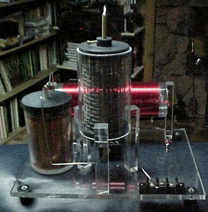
Edwin Gray's Capacitor Tube
"Power Plant of the Future"
(Unidentified reference/author: apparently EvGray Enterprises)
Would you believe, a battery-powered motor that recycles energy, hence is better than 90% efficient?
How? By generating electric pulses of 2,500 volts by means of an EvGray generator and storage in an oil-filled capacitor bank and introducing it into field and rotor winding at precisely the right moment by means of a patented programmer on the front of the rotor shaft.
Performance: Tests conducted on the 32 HP test model by Crosby Research Institute (Beverly Hills, CA), exacted the following:
The EMA motor was operated into a 10 HP dynamometer load at 1100 rpm. This power output is 7460 watts. The total battery power available from the four batteries was 5454 watts for one hour. The total battery power consumed by the motor during a 21-minute run was only 9.75 watts; this equals 26.8 watts per hour.
The system operated continuously for 203 hours (8-1/2 days) at 10 HP and 1100 rpm with the four batteries without recharging.
The batteries used were common lead acid with 2-3 years life expectancy, and can be recharged several hundred times.
General: The estimated performance figures, using the 50 HP motor in a car, are 300 miles per charge with top speeds in excess of 50 mph. This astounding prediction is a conservative one based on the performance of present electric car performance and the many tests conducted at EvGray.
We have also developed a fast-charge, low resistance battery, because of a new method of building lead acid batteries that will permit a 12 volt, 14 amp battery to be charged in 10 minutes with normal 2-3 year life expectancy (Not yet being manufactured). Tattler Weekly carries an occasional progress report on this motor.
US Patent # 3,890,548
Pulsed Capacitor Discharge Electric Engine
( Cl. 318/139 ~ June 17, 1975 )
Edwin V. Gray
Abstract ~
There is disclosed herein an electric machine or engine in which a rotor cage having an array of electromagnets is rotatable in an array of electromagnets, or fixed electromagnets are juxtaposed against movable ones. The coils of the electromagnets are connect3ed in the discharge path of capacitors charged to relatively high voltage and discharged through the electromagnetic coils when selected rotor and stator elements are in alignment, or when the fixed electromagnets and movable electromagnets are juxtaposed. The discharge occurs across spark gaps disclosed in alignment with respect to the desired juxtaposition of the selected movable and stationary electromagnets. The capacitor discharges occur simultaneously through juxtaposition of the selected movable electromagnets wound so that their cores are in magnetic repulsion polarity, thus resulting in the forced motion of movable electromagnetic elements away from the juxtaposed stationary electromagnetic elements at the discharge, thereby achieving motion. In an engine, the discharges occur successively across selected ones of the gaps to maintain continuous rotation. Capacitors are recharged between successive alignment positions of particular rotor and stator electromagnets of the engine.
Background of the Invention ~
1. Field of the Invention:
There is no known engine or motor operated on the principle of the present invention, that a capacitor charged to a relatively high voltage from a low-voltage DC source is discharged across a spark gap to provided current through motor drive coils in the discharge path, these being solenoids which generate motion by magnetic repulsion of juxtaposed pairs of cores. The solenoids are preferably configured in motor and stator assemblies to effect motion of the rotor element with respect to the stator.
The present invention utilizes this principle to provide a rotary motion machine or engine which can develop considerable torque through the magnetic repulsion action of rotor and stator cores wound with coils through which capacitors are discharged synchronously with the positioning of the rotor coils opposite particular stator coils. Similarly, a linear action can be achieved with a stationary electromagnet juxtaposed against a movable electromagnet and the movable electromagnet can perform work with a tool or piston attached thereto.
A novel control mechanism is associated with the rotor is the engine to position discharge elements appropriately to create the desired discharge through the electromagnet coils when the juxtaposed rotor and stator electromagnets are in alignment. The electromagnets in the stator and rotor are so arranged that the control mechanism can advance or retard the discharge points relative to rotor-stator positions for control of rotational speed.
The discharge overshoot or back emf from the collapsing fields in the coils from the capacitor discharge is used to energize external batteries for conservation of power. The recovered energy thus stored may be used to operate equipment associated with the engine or motive force-producing device.
The engine or rotary electric machine of the invention is believed to operate on the principle of conservation of energy, in that once rotation is achieved, current is needed only a the instant of a capacitor discharge in order to advance the rotor. The rotor moves to the next discharge point on the inertia of the repulsion action. The capacitor is recharged during the interval and stores the energy until the discharge at the next rotor-stator coil coincidence. Thus, the new engine produces torque and stores the excess energy for subsequent use.
In a linear motion device according to the invention, only a single pulse discharge is needed to perform work.
The applications of the engine include use as an electric automotive engine which is economical and which can regenerate a part of the energy consumed to provide power for other loads in the automotive electric vehicle. As a linear actuator an economical use of power is possible because each stroke will result from a single discharge pulse of a capacitor through a coil.
2. Prior Art:
An extensive prior art search by the applicant uncovered no capacitor-discharge operated motor resembling that of the present invention. All motors of the patents located in the search employed direct electrical connection between coils and electric power sources. When selective switching is involved, semiconductor devices are employed, such as silicon-controlled rectifiers. Capacitors are used only for starting and phasing purposes, and not for basic motor operation from the discharge thereof, as in this invention.
Summary of the Invention ~
This invention relates to electric motors or engines, and more particularly to a new electric machine including electromagnetic poles in a stator configuration wherein in one form thereof the rotor is rotatable within the stator configuration and where both are energized by capacitor discharges through rotor and stator electromagnets at the instant of the alignment of a rotor electromagnet with a stator electromagnet. The rotor electromagnet is repelled from the stator electromagnet by the discharge of the capacitor through the coils of both the stator and rotor electromagnets at the same instant.
In an exemplary rotary engine according to this invention, rotor electromagnets may be disposed 120 degrees apart on a central shaft and major stator electromagnets may be disposed 40 degrees apart in the rotor housing about the stator periphery. Other combinations of rotor elements and stator elements may be utilized to increase torque or rotation rate.
In another form, a second electromagnet is positioned to one side of each of the major stator electromagnets on a center line 13-1/2 degrees from the center line of the stator magnet, and these are excited in a predetermined pattern or sequence. Similarly to one side of each major rotor electromagnet is a second electromagnet spaced on a 13-1/2 degree center line from the major rotor electromagnet. Electromagnets in both the rotor and stator assemblies are identical, the individual electromagnets of each being aligned axially and the coils of each being wired so that each rotor electromagnetic pole will have the same magnetic polarity as the electromagnet in the stator with which it is aligned and which it is confronting at the time of discharge of the capacitor.
Charging of the discharge capacitor or capacitors is accomplished by an electrical switching circuit wherein electrical energy from a battery or other source of DC potential may be applied in alternating polarity to ignition coils or other voltage step-up arrangements from which a high voltage DC potential is derived through rectification by diodes.
The capacitor charging circuit comprises a pair of high frequency switches which feed respective automotive-type ignition coils employed as step-up transformers. The "secondary" of each of the ignition coils provides a high-voltage square wave to a half-wave rectifier to generate a high voltage output pulse of DC energy with each switching alternation of the high frequency switcher. Only one polarity is used so that a unidirectional pulse is applied to the capacitor bank being charged.
Successive unidirectional pulses are accumulated on the capacitor or capacitor bank until discharged. Discharge of the bank of capacitors occurs across a spark gap by arc-over. The gap spacing determines the voltage at which discharge or arc-over occurs. An array of gaps is created by fixed elements in the engine housing and moving elements positioned on the rotor shaft. At the instant when the moving gap elements are positioned opposite fixed elements during the rotor rotation, a discharge occurs through the coils of the aligned rotor and stator electromagnets to produce the repulsion action between the stator and rotor electromagnet cores.
A plurality of fixed gap elements are arrayed in the motor housing to correspond to the locations of the stator electromagnets in the housing. The rotor gap elements correspond to the positions of the rotor electromagnets on the rotor so that at the instant of correct alignment of the gaps the capacitors are discharged to produce the necessary current through the stator and rotor coils to cause the electromagnets to repel one another.
The charging circuits are arranged in pairs, and are such that the discharge occurs through both rotor and stator windings of the electromagnets, which are opposite one another when the spark gap elements are aligned and arc-over.
The speed of the rotor can be changed by means of a clutch mechanism associated with the rotor. The clutch shifts the positions of the rotor gap elements to that the discharge will energize the stator coils in a manner to advance or retard the time of discharge with respect to the normal rotor/stator alignment positions. The discharge through the rotor and stator then occurs when the rotor has passed the stator 6-2/3 degrees for speed advance.
By causing the discharge to occur when the rotor position is approaching the stator, the repulsion pulse occurs 6-2/3 degrees before the alignment position of the rotor and stator electromagnets, thus slowing the speed.
The clutch mechanism for aligning capacitor discharge gaps for discharge is described as a control head. It may be likened to a firing control mechanism in an automobile combustion engine in that it "fires" the electromagnets and provides a return of any discharge overshoot potential back to the battery or other energy source.
The action of the control head is extremely fast. From the foregoing description, it can be anticipated that an increase in the speed or a decrease in speed of rotation can occur within the period in which the rotor electromagnet moves between any pair of adjacently located electromagnets in the stator assembly, which are 40 degrees apart in the exemplary engine according to the invention. Thus, speed changes can be effected in a maximum of one-ninth of a revolution.
The rotor speed-changing action of the control head and its structure are believed to be further novel features of the invention, in that they maintain normal 120 degree firing positions during uniform speed or rotation conditions, but shift to + 6-2/3 degrees longer or shorter intervals for speed change by the novel shift mechanism in the rotor clutch assembly.
Accordingly, the preferred embodiment of this invention is an electric rotary engine wherein motor torque is developed by discharge of high potential from a bank of capacitors through stator and rotor electromagnet coils when the electromagnets are in alignment. The capacitors are charged from batteries by a switching mechanism, and are discharged across spark gaps set to achieve the discharge of the capacitor charge voltage through the electromagnetic coils when the gaps and predetermined rotor and stator electromagnet pairs are in alignment.
Exemplary embodiments of the invention are herein illustrated and described. These exemplary illustrations and description should not be construed as limiting the invention to the embodiments shown, because those skilled in the arts pertaining to the invention may conceive of other embodiments in the light of the description within the ambit of the appended claims.
Brief Description of the Drawings ~
Figure 1 is an explanatory schematic diagram of a capacitor charging and discharging circuit utilized in the present invention;
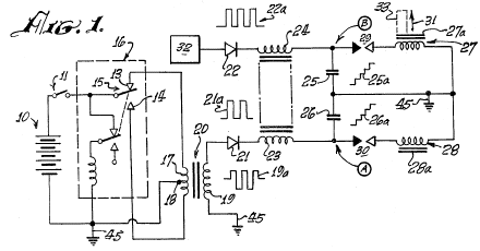
Figure 2 is a block diagram of an exemplary engine system according to the invention;

Figure 3 is a perspective view of a typical engine system according to the invention, coupled to an automotive transmission;
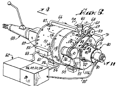
Figure 4 is an axial sectional view taken at line 4-4 in Figure 3;
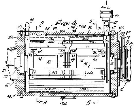
Figure 5 is a sectional view taken at line 5-5 in Figure 4;
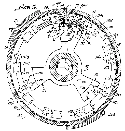
Figure 6 and Figure 7 are fragmentary sectional views, corresponding to a portion of Figure 5, illustrating successive advanced positions of the engine rotor therein;
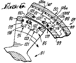
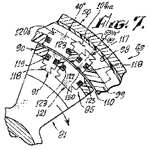
Figure 8 is an exploded perspective view of the rotor and stator of the engine of Figures 3 and 4;
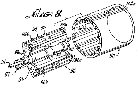
Figure 9 is a cross-sectional view taken at line 9-9 of Figure 4;
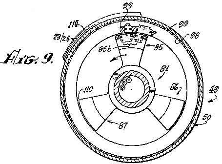
Figure 10 is a partial sectional view, similar to the view of Figure 9, illustrating a different configuration of electromagnets in another engine embodiment of the invention;
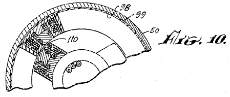
Figure 11 is a sectional view taken at line 11-11 in Figure 3, illustrating the control head or novel speed change controlling system of the engine;
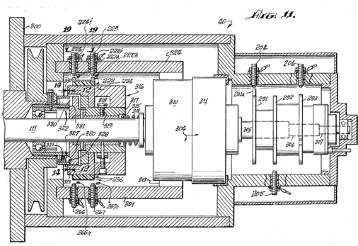
Figure 12 is a sectional view, taken at line 12-12 in Figure 11, showing a clutch plate utilized in the speed control system of Figure 11;
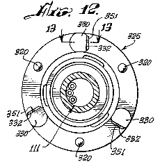
Figure 13 is a fragmentary view, taken at line 13-13 in Figure 12;
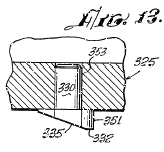
Figure 14 is a sectional view, taken at line 14-14 in Figure 11, showing a clutch plate which operates with the clutch plate of Figure 12;
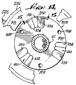
Figure 15 is a fragmentary sectional view taken at line 15-15 of Figure 13;
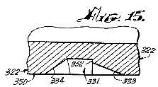
Figure 16 is a perspective view of electromagnets utilized in the present invention;
Figure 17 is a schematic diagram showing cooperating mechanical and electrical features of the programmer portion of the invention;
Figure 18 is an electrical schematic diagram of an engine according to the invention, showing the electrical relationships of the electromagnetic components embodying a new principle of the invention; and
Figure 19 is a developed view, taken at line 191-19 of Figure 11, showing the locations of displaced spark gap elements of the speed changing mechanism of an engine according to the invention.
Description of the Preferred Embodiment ~
As hereinbefore mentioned, the basic principle of operation of the engine of the invention is the discharge of a capacitor, across a spark gap through an inductor. When a pair of inductors is used, and the respective magnetic cores thereof are arranged opposite and another in magnetic polarity repulsion relation, the discharge through them causes the cores to repel each other with considerable force.
Referring to the electrical schematic diagram of Figure 1, a battery 10 energizes a pulse-producing vibrator mechanism 16, which may be of the magnetic type incorporating an armature 15 moving between contacts 13 and 14, or of the transistor type (not shown) with which a high frequency bipolar pulsed output is produced in primary 17 of transformer 20. The pulse amplitude is stepped up in secondary 19 of transformer 20. Wave form 19a represents the bi-directional or bipolar pulsed output. A diode rectifier 21 produces a unidirectional pulse train, as indicated at 21a, to charge capacitor 26. A delay coil 23 is connected in series with the unipolar pulsed output to capacitor 26. Successive unidirectional pulses of wave 21a charge capacitor 26 to a high level, as indicated at 26a, until the voltage amplitude at point A reaches the breakdown potential of spark gap 30. At the breakdown of spark gap 30, capacitor 26 discharges across the arc created through the inductor coil 28. A current pulse is produced which magnetizes core 28a. Simultaneously, another substantially identical charging system 32 produces a discharge through inductor 27 across spark gap 29 to magnetize core 27a. Cores 28s, 27a are wound with coils 28, 27 so that their magnetic polarities are the same. As the cores 27a, 28a confront one another, they tend to fly apart when the discharge occurs through coils 27 and 28 because of repulsion of identical magnetic poles, as indicated by arrow 31. If core 28a is fixed or stationary and core 27a is movable, then core 27a may have tools 33 attached to it to perform work when the capacitor discharges.
Referring to Figures 1 and 2, a DC electrical source or battery 10 energizes pulsators 36 (including at least two vibrators 16 as previously described) when switch 11 between the battery 10 and pulsator 36 is closed, to apply relatively high frequency pulses to the primaries of transformers 20. The secondaries of transformers 20 are step-up windings which apply bipolar pulses, such as pulses 19a (Figure 1) to the diodes in converter 38. The rectified unidirectional pulsating output of each of the diodes in converter 38 is passed through delay coils 23, 24, thus forming a harness 37 wound about the case of the engine, as hereinafter described, which is believed to provide a static floating flux field. The outputs from delay lines 37 drive respective capacitors in banks 39 to charge the capacitors therein to a relatively high charge potential. A programmer and rotor and stator magnet control array 40, 41, 42 is formed by spark gaps positioned, as hereinafter described, so that at predetermined positions of the rotor during rotation of the engine, as hereinafter described, selected capacitors of capacitor banks 39 will discharge across the spark gaps through the rotor and stator electromagnets 43, 44. The converters 38, magnetic harness 37, capacitor banks 39, programmer 40, and controls 41, 42 form a series circuit path across the secondaries of transformer 20 to the ground, or point of reference potential, 45. The capacitor banks 39 are discharged across the spark gaps of programmer 40 (the rotor and stator magnet controls 41, 42). The discharge occurs through the coils of stator and rotor electromagnets 43, 44 to ground 45. Stator and rotor electromagnets are similar to those shown at 27, 27a, 28, 28a in Figure 1.
The discharge through the coils of stator and rotor electromagnets 43, 44 is accompanied by a discharge overshoot or return pulse, the output of which is applied in an appropriate polarity to a secondary battery 10a to store this excess energy. The overshoot pulse returns to battery 10a because after discharge the only path open is that to battery 10a, since the gaps in 40, 41, and 42 have broken down, because the capacitors in banks 39 are discharged and have not yet recovered the high voltage charge from the high frequency pulsers 36 and converter rectifier units 38.
In the event of a misfire in the programmer control circuits 40, 41, 42,the capacitors are discharged through a rotor safety discharge circuit 46 and returned to batteries 10-10a, adding to their capacity. The circuit 46 is connected between the capacitor banks 39 and batteries 10, 10a.
Referring to Figure 3, a motor or engine 49 according to the present invention is shown connected with the automotive transmission 48. The transmission 48 represents one of many forms of loads to which the engine may be applied. A motor housing 50 encase the operating mechanism hereinafter described. The programmer 40 is axially mounted at one end of this housing. Through aperr4es 51, 52, a belt 53 couples to a pulley 57 (not shown in this view) and to an alternator 54 attached to housing 50. A pulley 55 on the alternator has two grooves, one for belt 53 to the drive pulley, and the other for a belt 58 coupled to a pulley 59 on a pump 60 attached to housing 50. A terminal box 61 on the housing interconnects means between the battery assembly 62 and motor 49 via cables 63 and 64.
An intake 65 for air is coupled to pump 60 via piping 68, 69 and from pump 60 via tubing or piping 66, 70 to the interior of housing 50 via coupling flanges 67 and 71. The air flow tends to cool the engine, and the air may preferably be maintained at a constant temperature and humidity so that a constant spark gap discharge condition is maintained. A clutch mechanism 80 is provided on programmer 40.
Referring to Figures 4, 5, and 9, rotor 81 has spider assemblies 83, 84 with three electromagnet coil assembly sets mounted thereon, two of which are shown in Figure 4, on 85 at 85a and 85b, and on 86 at 86a and 86b. One of the third electromagnet coil assemblies, designated 871, is shown in Figure 5, viewed from the shaft end. As more clearly shown in the perspective view of Figure 8, a third spider assembly 88 provides added rigidity and a central support for the rotor mechanism on shaft 81.
The electromagnet sets 85a and 85b, 86a and 86b, 87a and 87b, disposed on rotor 81 and spiders 83, 84, and 88 each comprise pairs of front units 85a, 86a, 87a and pairs of rear units 85b, 86b, 87b. Each pair consists of a major electromagnet and a minor electromagnet, as hereinafter described, which are embedded in an insulating material 90, which insulates the electromagnet coil assemblies from one another and secures the electromagnets rigidly in place on the spider/rotor cage 81, 83, 84, 88.
The interior wall 98 of housing 50 I coated with an electrically insulating material 99 in which are embedded electromagnet coils, as hereinafter described, and the interiors of end plates 100, 01, of the housing 50. On the insulating surface 98 of housing 50 is mounted a series of stator electromagnet pairs 104a, identical with electromagnet pairs 85a, 86a, 87a, etc. Electromagnet pairs such as 104a and 105a are disposed every 40 degrees about the interior of housing 50 to form a stator which cooperates with the rotor 81-88. An air gap 110 of very close tolerance is defined between the rotor and stator electromagnets, and air from pump 65 flows through this gap.
As shown in Figure 8, the electromagnet assemblies, such as 85 through 87, of the rotor and magnet assemblies, such as 104a in the stator are so embedded in their respective insulative plastic carriers (rotor and stator) that they are smoothly rounded in a concave contour for the stator, and in a convex contour on the rotor to permit smooth and continuous rotation of rotor 81 in stator housing 50. The air gap 110 is uniform at all positions of any rotor element within the stator assembly, as is clearly shown in Figure 16.
The rotor 81 and spiders 83, 84, 88 are rigidly mounted on a shaft 111 journaled in bearing assemblies 12, 113 which are of conventional type, for easy rotation of the rotor on shaft 111 within housing 50.
Around the central outer surface of housing 50 are wound a number of turns of wire 23, 24 to provide a static flux coil 114 as hereinbefore described, which is a delay line, as previously described.
Figures 5, 6, 7 and 9 are cross-sectional views of the rotor assembly 81-88, arranged to show the positioning and alignment of the rotor and stator assemblies at successive stages of the rotation of rotor 81-88 through a portion of a cycle of operation thereof. For example, I Figure 5 the rotor assembly 81-88 is shown so positioned that a minor stator electromagnet assembly 91 is aligned with a minor electromagnet assembly 117.
As shown in further detail in Figure 16, minor electromagnet assembly 117 consists of an iron core 118, grooved so that there may be wound thereabout a coil of wire 119. Core 118 is the same in stator electromagnet 117 as it is in rotor electromagnet 91.
At a position 13-1/2 degrees to the right of rotor electromagnet 91, as viewed in Figure 5, there is a second or major stator electromagnet 120 whose core 122 is of the same configuration as core 122 of rotor electromagnet 121. A winding 123 about core 122 of electromagnet 120 is of the same character as winding 123 on electromagnet 121.
Electromagnet assembly pair 85a on the rotor is identical in configuration with that of the electromagnet stator assembly pair 104a except for the position reversal of the elements 117-120 and 91-121 of the respective pairs.
There are nine pairs of electromagnets 120-117 (104a) disposed at 40-degree intervals about the interior of housing 50. The center line of core 122 of electromagnet 120 is positioned 13-1/2 degrees to the left of the center line of the core 118 of electromagnet 117. Three pairs of electromagnets 85a, 86a, 87a, are provided on rotor assembly 81-88 as shown in Figure 5.
Other combinations are possible, but the number of electromagnets in the rotor should always be an integral fraction of the number of electromagnets in the stator. As shown in Figure 8, for the rotor assembly 85a, 85b, there are three of each of the front and back pairs of electromagnetic assemblies. Similarly, as shown in Figures 4 and 8, there are nine front and back pairs of electromagnets in the stator such as 104a and 104b.
In order to best understand the operation of the rotor 81-88 rotating within the stator housing 50 of an engine according to this invention, the positions of rotor electromagnets 91 and stator electromagnets 117 are initially exactly in line at the 13-1/2 degree peripheral starting position marked on the vertical center line of figure 5. The winding direction of the coils of these magnets is such that a DC current through the coils 119 will produce a particular identical magnetic polarity on each of the juxtaposed surfaces 125 of magnets 117 and 126 of magnet 91 (Figure 5). Figures 6 and 16 illustrate the next sep in motion wherein the two major electromagnets, 120 in the stator and 121 in the rotor, are in alignment.
When the DC-discharges from the appropriate capacitors in banks 39 occur simultaneously across spark gaps through the coils 119 of electromagnets 117 and 91, at the instant of their alignment, their cores 118 will repel one another to cause rotor assembly 81-88 to rotate clockwise in the direction indicated by arrow 127. The system does not move in the reverse direction because it has been started in the clockwise direction by the alternator motor 54 shown in Figure 3, or by some other starter means. If started counterclockwise, the rotor will continue to move counterclockwise.
As hereinbefore noted, the discharge of any capacitor occurs over a very short interval across its associated spark gap, and the resulting magnetic repulsion action imparts motion the rotor. The discharge event occurs when electromagnets 117 and 91 are in alignment. As shown in Figure 5, rotor electromagnet 91a is aligned with stator electromagnet 117c, and rotor electromagnet 91b is aligned with stator electromagnet 1173 at the same time that similar electromagnets 117 and 91 are aligned. A discharge occurs through all six of these electromagnets simultaneously (that is, 117, 91; 117c, 91a; 117e and 91b). A capacitor and a spark gap are required for each coil of each electromagnet. Where, as in the assembly shown in Figure 8, front and back pairs are used, both the axial in-line front and back coils are energized simultaneously by the discharge from a single capacitor or from a bank of paralleled capacitors such as 25, 26 (Figure 1). Although Figures 4 and 8 indicate the used of front and back electromagnets, it should be evident that only a single electromagnet in any stator position and a corresponding single electromagnet in the rotor position, may be utilized to accomplish the repulsion action of the rotor with respect to the stator. As stated, each electromagnet requires a discharge from a single capacitor or capacitor bank across a spark gap for it to be energized, and the magnetic polarity of the juxtaposed magnetic core faces must be the same, in order to effect the repulsive action to produce the rotary motion.
Referring to Figures 5 and 6, the repulsion action causes the rotor to move 13-1/3 degrees clockwise, while electromagnets 91, 91a and 91b move away from the electromagnets 117, 117c and 117e to bring electromagnets 121, 121a and 121b into respective alignment with electromagnets 120a, 120d and 120f. At this time, a capacitor discharge across a spark-gap into their coils 123 occurs, thus moving the rotor. Another 13-1/3 degree ahead, as shown in Figure 7, major electromagnets 121, 121a and 121b come into alignment with minor electromagnets 117a, 117d and 117f, at which time a discharge occurs to repeat the repulsion action, this action continuing as long as DC power is applied to the system to charge the capacitors in the capacitor banks.
Figure 18 further illustrates the sequencing of the capacitor discharges across appropriate spark gap terminal pairs. Nine single stator coils and three single rotor coils are shown with their respective interconnections with the spark gaps and capacitors with which they are associated for discharge. When the appropriate spark gap terminals are aligned, at the points in the positioning of the rotor assembly for most effective repulsion action of juxtaposed electromagnet cores, the discharge of the appropriate charged capacitors across the associated spark gap occurs through the respective coils. The capacitors are discharged in sets of three through sets of three coils at each discharge position, as the rotor moves through the rotor positions. In Figure 18, the rotor electromagnets are positioned linearly, rather than on a circular base, to show the electrical action of an electric engine according to the invention. These motor electromagnets 201, 202, and 203 are aligned with stator electromagnets 213, 214, and 215 at 0 degrees, 120 degrees and 450 degrees respectively. The stator electromagnets are correspondingly shown in a linear schematic as if rolled out of the stator assembly and laid side by side. For clarity of description, the capacitors associated with the rotor operation 207, 208, 209 and 246, 247, 248, 249, 282 ad 283 are arranged in vertical alignment with the respective positions of the rotor coils 201, 202, 203 as they move from left to right, this corresponding to clockwise rotation of the rotor. The stator coils 213, 214, 215, 260, 261, 262, 263, 264, 265, 266, etc., and capacitor combinations are arranged side by side, again to facilitate description.
An insulative disc 236 (shown in Figure 17 as a disc, but opened out linearly in Figure 18) has mounted thereon three gap terminal blocks 222, 225 and 228. Each block is rectangularly U-shaped, and each interconnects two terminals with the base of the U. Block 222 has terminals 222a and 222b, block 225 has terminals 225a and 225b, block 228 has terminals 228c and 228d. When insulative disc 230 is part of the rotor, as indicated by mechanical linkage 290, it can be seen that terminal U 222 creates a pair of gaps with gap terminals 223 and 224, respectively. The stator electromagnets are correspondingly shown in linear schematic as if rolled out of the stator assembly and laid side by side. For clarity of description, the capacitors associated with the rotor operation 207, 208, 209, and 246, 247, 248, 249, 282 and 283 are arranged in vertical alignment with the respective positions of the rotor coils 201, 202, 203 as they move from left to right, this corresponding to clockwise rotation of the motor. The stator coils 213, 214, 215, 260, 261, 262, 263, 264, 265, 266, etc., and capacitor combinations are arranged side by side, again to facilitate description.
An insulative disc 236 (shown in Figure 17 as a disc, but opened out linearly in Figure 18) has mounted thereon three gap terminal blocks 222, 225, and 228. Each block is rectangularly U-shaped, and each interconnects two terminals with the base of the U. Block 222 ha terminals 222a and 222b, block 225 has terminals 225a and 225b, and block 228 has terminals 228c and 228d. When insulative disc 230 is part of the rotor, as indicated by mechanical linkage 290, it can be seen that terminal U 222 creates a pair of gaps with terminals 223 and 224, respectively. Thus, when the voltage on capacitor 216 from charging circuit 219 is of a value which will arc over the air spaces between 222a and 223, and between 222b and 224, the capacitor 216 will discharge into the coil of electromagnet 213 to ground. Similarly gap terminal U 225 forms a dual spark gap with terminals 226 and 227 to result in arc-over when the voltage on capacitor 217, charged by charging circuit 220, discharges into the coil of electromagnet 214. Also, U-gap terminal 228 with terminals 228c and 228d, creates a spark gap with terminals 229 and 230 to discharge capacitor 218, charged by charging circuit 221, into coil 215. At the same time, rotor coils 201, 202 and 203 across gaps 201a-204, 202b-205 and 203c-206 each receives a discharge from respective capacitors 207, 208 and 209.
When the electromagnet coils 213, 214, 215 an 201, 202, 203 are energized, the repulsion action causes the rotor assembly to move to position 2 where a new simultaneous group of discharges occurs into rotor coils 201, 202, and 203 from capacitors 246, 248, and 282 across gaps 201a-240, 202b-242 and 203c-244. Simultaneously, because gap U-elements 222, 225, and 228 have also moved to position 2 with the rotor assembly, capacitor 261 is discharged through electromagnet coil 260, capacitor 265 is discharged through electromagnet coil 264, and capacitor 269 is discharged through electromagnet coil 168 in alignment with position 2 of the rotor electromagnet coils, thus to cause the rotor electromagnets to move to position 3 where the discharge pattern is repeated now with capacitors 247, 249 and 283 discharging through the rotor electromagnet coils 201, 202, 203, and the capacitors 263, 267 and 281 discharging respectively through stator electromagnet coils 262, 266 and 280.
After each discharge the charging circuits 219-221 and 272-277 for the stator capacitors, and 210-212 and 284-289 for the rotor capacitors, are operated continuously from a battery source, as described earlier with reference to Figure 1, to constantly recharge the capacitors to which each is connected. Those versed in the art will appreciate that, as each capacitor discharges across an associated spark gap, the resulting drop in potential across the gap renders the gap an open circuit until such time as the capacitor can recharge to the arc-over level of the gap. This recharge to a discharge potential occurs before a rotor element arrives at the next position in question.
The mechanical schematic diagram of Figure 17 further clarifies the operation of the spark-gap discharge programming system. A forward disc 236 of an electrically insulative material, has thereon the set of U-shaped gap terminal connectors previously described. These are positioned at 0 degrees, 120 degrees and 240 degrees respectively. In Figure 17, schematic representations of the position of the coil and capacitor combinations at the start of a cycle are shown to correspond to the description hereinabove with reference to Figure 18. Accordingly, the coil and capacitor combinations 213/216, 214/217, and 215/218 are shown connected with their gap terminals, respectively, 223/224, 226/227, and 229/230. On the rotor coil and capacitor connection three separate discs 291, 292 and 293 are shown, each with a single gap terminal. The discs 291-293 are rotated so as to position their respective gap terminals 201a, 202b and 203c at 120 degree increments, with the 0 degree position corresponding to the 0 degree position of U-gap terminal 222 on disc 230.
Representative gap terminals are shown about the peripheries of discs 230, 291-193 to clearly indicate how, as the discs turn in unison, the gap alignments correspond so that three rotor coil/capacitors always line up at 120 degree intervals about the rotary path, producing an alignment every 40 degrees, there being nine stator coils. Thus there are three simultaneous discharges into stator coils and three into rotor coils at each 40 degree position. Nine positions displaced 40 degrees apart provide a total of 27 discharge points for capacitors into the stator coils in one revolution.
It will be understood that, as illustrated in Figures 17 and 18, nine individual electromagnet coils are shown in the stator and three in the rotor, in order to show in its simplest form how the three rotor electromagnets are stepped forward from the alignment with three of the stator electromagnets, when the appropriate spark gaps are in alignment, to effect the discharge of capacitors through juxtaposed pairs of rotor/stator electromagnets. The repulsion moves the rotor electromagnet from the stator electromagnet to the next alignment position advanced at an arc of 40 degrees from the preceding alignment position. In the interval until another rotor electromagnet, 120 degrees removed, is aligned with the stator electromagnet that has just been excited, the associated capacitor is recharged to a potential which will cause the spark gap to break down to produce another discharge of this capacitor on the next revolution. Thus the rotor moves from one position to the next, with capacitor discharges occurring each 40 degrees of rotation, a total of nine per revolution. It should be obvious that, with other rotor/stator combinations, the number of electromagnet coincidences and spark-gap discharges will vary. For example, with the coil pairs shown in Figures 4 through 8, a total of 27 discharges will occur. Although there are 18 stator electromagnets and three rotor electromagnets, the discharge pattern is determined by the specific spark gap arrangement.
The rotor/stator configuration of Figures 5 and 8, involving the major and minor pairs of electromagnets such as 85a and 104a (the terms "major" and "minor" referring to the difference in size of the elements), include nine pairs of electromagnets in the stator, such as 104a, with three electromagnet pairs of the rotor, such as 85a. Because of the 13-1/3 degree separation between the major and minor electromagnets in the rotor pair 85a, with the same separation of minor and major electromagnets of the stator pair 104a, the sequence of rotation and discharge described above, with respect to the illustrative example of Figure 5, involves the following:
(1) A minor element 117 of stator pair 104a is aligned with the minor element 91 of rotor pair 85a. On the discharge, this moves the rotor ahead 13-1/3 degrees.
(2) The major rotor element 122 of the pair 85a now is aligned with the major stator element 120b of the next electromagnet pair, in the stator array as shown in Figure 6. On the discharge, the rotor moves ahead 13-1/3 degrees.
(3) This brings the minor rotor electromagnet 91 into alignment with the major stator element 120 b of pair 104d, and the major electromagnet 122 (just discharged) of pair 85a into alignment with minor electromagnet 117b of pair 104d, and the rotor spark gap elements into alignment with a different position of gap elements connected with capacitors not discharged in the previous position of the rotor. It should be remembered at this point that it is the positioning of a rotatable spark gap array, similar to that illustrated in Figures 17 and 18, which controls the time of discharge of capacitors connected to these gap terminals. Therefore, any electromagnet can be energized twice successively from separate capacitors as the motor brings appropriate gap terminals into alignment with the coil terminals of a particular electromagnet.
Thus, although major electromagnet 120b of pair 104d has just been energized as described above, it can now be energized again along with minor rotor electromagnet 91 in step 3, because the rotor moved to a new set of terminals of the spark gap arrays connected with capacitors not yet discharged. These capacitors now discharge through rotor electromagnet 91 and stator electromagnet 120b, causing rotor to move ahead another 13-1/3 degrees, thus again aligning two minor electromagnets again, these being 117b of stator pair 104 d and 91 of rotor pair 85a. The rotor has now moved 40 degrees since step 1 above. The sequence is repeated, and it is to be noted that at each 13-1/3 degree step, the discharges rotate the rotor another 13-1/3 degrees. There are 27 steps per revolution with nine stator coil pairs. The discharge sequence is not uniform, as is shown in Table 1. In the stator, three major electromagnets 120 degrees apart are energized twice in sequence followed by a hiatus of one step while three minor electromagnets of the stator, 120 degrees apart, are energized during the hiatus. In the rotor the major electromagnets are energized during a hiatus step following two minor electromagnet energization steps. A total of 27 energizations are thus accomplished in the nine pairs of coils of the stator.
In Table 1, the leftmost column depicts the location of each rotor arm 85, 86, 87 at an arbitrarily selected step No. 1 position. For example, in step 1 rotor arm 85 has a minor stator and minor rotor electromagnet in alignment for capacitors to discharge through them simultaneously at the 13-1/3 degree position.
Table 1: Capacitor Discharge Sequence for One Revolution of Rotor in System of Figures 5 & 8
Similarly, in step 1 rotor arm 86 is at the 133-1/2 degree position with a minor rotor and minor stator electromagnet in alignment for discharge. Simultaneously, rotor arm 87 is at the 253-1/3 degree position with a minor rotor and minor stator in alignment for capacitor discharge therethrough. The other steps of the sequence are apparent from Table 1, for each position of the three rotor arms at any step and the juxtapositions of respective stator and rotor electromagnet elements at that position.
In the simplified motor arrangement shown in schematic form in Figure 18, with single electromagnet configuration the alignment is uniform and the discharge sequences follow sequentially.
As hereinafter mentioned, a change in speed is effected by displacing the stator spark gap terminals on the rotor (shown at 236 in Figures 17 and 18) either counter-clockwise or clockwise 6-2/3 degrees so that the discharge position of the stator electromagnets is displaced 6-2/3 degrees either clockwise or counter-clockwise of the rotor electromagnet at the time of discharge. Referring to Figures 11 to 15, the simultaneous discharge of selected capacitors into the electromagnets so displaced results in a deceleration at the time the rotor electromagnet is just approaching the associated stator, or an acceleration if the rotor electromagnet is just leaving its associated stator electromagnet. In each event, there is a repulsive reaction between the stator and rotor electromagnets, so that if the rotor is approaching the stator, there is a slow-down and if the rotor is receding from the stator there is a speed-up.
Referring to Figure 11, clutch mechanism 304 about shaft 111 is operated electromagnetically in conventional manner to displace the spark-gap mechanism 236 which is operated in appropriate matching alignment with the rotor spark-gap discs 291, 292, 293. Clutch 304 has a fixed drive element 311 containing an electromagnetic drive coil (not shown) and a motor element 310 which, when the electromagnetic drive coil is energized, can be operated by a direct current. The operation of motor element 310 brings into operation spark gap elements 224r, 223r or 223f, 224f of the system shown in Figures 4, 5, and 8, as illustrated in Figure 19.The fixed stator coil spark gap terminal pairs 223, 224 and 266, 267 are arrayed about a cylindrical frame 322 which is fabricated in insulative material. In the illustrative example of Figures 17 and 18, there are nine such spark gap terminal pairs about the periphery of cylinder frame 324. In the engine of Figures 4 to 8, a total of 27 such spark gap pairs are involved. In addition, although not shown in the drawing, there are also pairs of terminals, such as 223r or 223f, 224r or 224f and 266r or 226f, 267r or 267f, displaced 6-2/3 degrees on either side of the pairs 223, 224, or 266, 267, and all other pairs in the spark gap array, the letters r and f denoting "retard" and "faster'. The latter displaced pairs are used in the control of speed of the engine rotor. The displaced pairs not shown are involved with the operation of clutch 304, the speed changing control element.
Clutch 304 is associated with shaft 111 in that the movable element 10 draws clutch disc element on shaft 111 away form clutch disc element 322 when energized by a voltage of appropriate polarity applied to its motor electromagnet 311. Such clutch drives are well known in the art.
The clutch mechanism 304 of Figures 11 and 19, when not energized is in the configuration shown in Figure 11. The energized configuration of clutch 304 is not specifically illustrated. Upon energization, spark-gap element 222 on disc 236 is displaced rightward, as viewed in Figure 11, by broken lines 236x, into alignment with the positions of fixed spark-gap terminals 223f, 224f and 267r, 266r. When the disc is in position 236x, the flattened edge 332 of pin 330 in disc 325 rides on surface 350 of disc 322. Normally, the flattened edges 351 of pins 330 are engaged against the flat edge 352 in recess 331 of disc 322. The displacement of disc 322 on shaft 111 is effected by the action of clutch 304 against spring 314 (Figure 11). An electric switch (not shown) of clutch mechanism 304 energizes it from a DC power source, and has two positions, one for deceleration and one for acceleration. In either position, clutch 304 is engaged to pull clutch disc 322 from clutch disc 325, momentarily. For the decelerate or accelerate position, the displaced alignment of spark gap elements 222 is with the 224f, 223f and the 224r, 223r spark-gap terminal elements. However, only the 224f, 223f spark-gap elements are switched into operation with appropriate capacitors for the accelerate position, while in the decelerate position only the 223r and 224r spark-gap elements are switched into the circuit with their associated capacitors.
Of course, when insulative disc 236 is displaced by clutch 304, its gap terminals 22, 225 and 228 (Figures 14 and 18) are all displaced into the alignment position of 236x so as to engage the r and f lines of fixed spark gap elements. Although the accelerate and decelerate positions of disc 236 are the same, it is the switching into operation of the 223, 224 or 266, 267 exemplary r or f pairs of terminals which determine whether speed up or slow down action of the rotor will occur.
The momentary displacement of clutch disc 322 from clutch disc 325 results in rotation of disc 325 about disc 322 through an angle 0f 120 degrees. The detent ball and spring mechanism 320, 321 in disc 325 positions itself between open detent dimple 328 and a succeeding one 328 at a position 120 degrees away on disc 325. As stated, flat 332 of pin 330 rides on surface 350 of disc 322, and pin 330 leaves the pin-holding groove 331/352 along ramp 333 in disc 322 during the momentary lifting of disc 322 by clutch 304. Pin 330 falls back into the next groove 331 at point 120 degrees further on about disc 322. Pin 330 falls into place in groove 331 on ramp 334. Pins 330 are rotatable in their sockets 353, so that for either clockwise or counterclockwise rotation, the flat 351 will engage the flat 352 by the particular ramp it encounters.
The deceleration or acceleration due to the action of clutch 304 thus occurs within a 120-degree interval of rotation of disc 325. Disc 322 during this interval may only move a fraction of this arc.
There has been described hereinabove an electromotive engine system wherein at least one electromagnet is in a fixed position and a second electromagnet of similar configuration is juxtaposed with it in a magnetic polarity relationship such that, when the cores of the electromagnets are energized, the juxtaposed core faces repel one another. One core being fixed and the second core being free to move, any attachments to the second electromagnet will move with it. Hence, if a plurality of fixed cores are positioned about a circular confining housing, and, within the housing, cores on a shaft are free to move, the shaft is rotationally urged each time the juxtaposed fixed and rotatable cores are in alignment and energized. Both the fixed and the movable cores are connected to spark gap terminal elements, and the associated other terminal elements of the spark gaps are connected to capacitors which are charged to a high voltage from pulsed unipolar signal generators. These capacitors are discharged through the electromagnets across the spark gaps. By switching selected groups of capacitors into selected pairs of spark gap elements for discharge through the electromagnets, the rotor of the circular array systems is accelerated and decelerated.
By confining a fixed electromagnet array in a linear configuration with a linearly movable electromagnet to which a working tool is attached, exciting the juxtaposed pairs of electromagnets by capacitor discharge results in the generation of linear force for such tools as punch presses or for discharging projectiles with considerable energy.
The inventor claims: [Claims not included here]
US Patent # 4,595,975
Efficient Power Supply Suitable for Inductive Loads
Edwin V. Gray, Sr.
( US Cl. 363-33, &c ~ June 17, 1986 )
Abstract ~
Disclosed is an Electrical Driving and Recovery System for a High Frequency environment. The recovery system can be applied to drive present day direct-current or alternating-current loads for better efficiency. It has a low-voltage source coupled to a vibrator, a transformer and a bridge-type rectifier to provide a high voltage pulsating signal to a first capacitor. Where a high-voltage source is otherwise available, it may be coupled directly to a bridge-type rectifier, causing a pulsating signal to the first capacitor. The first capacitor in turn is coupled to a high voltage anode of an electrical conversion switching element tube. The switching element tube also includes a low voltage anode which is connected to a voltage source by a commutator and a switching element tube. Mounted around the high voltage anode is a charge receiving plate which is coupled to an inductive load to transmit a high voltage discharge from the switching element tube to the load. Also coupled to the load is a second capacitor for storing the back EMF created by the collapsing electrical field of the load when the current to the load is blocked. The second capacitor is coupled to the voltage source. When adapted to present day direct-current or alternating-current devices the load could be a battery or capacitor to enhance the productivity of electrical energy.
Inventors: Gray, Sr.; Edwin V.
(P.O. Box 362, Council, ID 83612)
Appl. No.: 662339 ~ Filed: October
18, 1984
Current U.S. Class: 363/33; 323/207;
323/228; 323/291; 363/94; 363/110
Intern'l Class: H02M 003/42
Field of Search: 315/33 S
363/32,33,76,94,109,110 323/207,227,228,291
References Cited ~
Foreign Patent Documents:
2030801 Mar., 1983 GB.
Primary Examiner: Beha, Jr.; William H.
~ Assistant Examiner: Sterrett, Jeffrey
Attorney, Agent or Firm: Nixon &
Vanderhye
Description ~
Background of the Invention
1. Field of the Invention:
The present invention relates to an electrical driving system and a conversion element, and more particularly, to a system for driving an inductive load in a greatly improved and efficient manner.
2. Description of the Prior Act:
In the opinion of the inventor, there is no known device which provides the conversion of energy from a direct-current electric source or an alternating-current electric source to a mechanical force based on the principle of this invention. EXAMPLE: A portable energy source, (1) such as a battery, (2) such as alternating-current, (3) such as the combination of battery and alternating-current, may be used with highly improved efficiency to operate a mechanical device, whose output is a linear or rotary force, with an attendant increase in the useful productive period between external applications of energy restoration for the energy source.
Summary of the Invention:
The present invention provides a more efficient driving system comprising a source of electrical voltage; a vibrator connected to the low-voltage source for forming a pulsating signal; a transformer connected to the vibrator for receiving the pulsating signal; a high-voltage source, where available, connected to a bridge-type rectifier; or the bridge-type rectifier connected to the high voltage pulse output of the transformer; a capacitor for receiving the voltage pulse output; a conversion element having first and second anodes, electrically conductive means for receiving a charge positioned about the second anode and an output terminal connected to the charge receiving means, the second anode being connected to the capacitor; a commutator connected to the source of electrical voltage and to the first anode; and an inductive load connected to the output terminal whereby a high energy discharge between the first and second anodes is transferred to the charge receiving means and then to the inductive load.
As a sub-combination, the present invention also includes a conversion element comprising a housing; a first low voltage anode mounted to the housing, the first anode adapted to be connected to a voltage source; a second high voltage anode mounted to the housing, the second anode adapted to be connected to a voltage source; electrically conductive means positioned about the second anode and spaced therefrom for receiving a charge, the charge receiving means being mounted to the housing; and an output terminal communicating with the charge receiving means, said terminal adapted to be connected to an inductive load.
The invention also includes a method for providing power to an inductive load comprising the steps of providing a voltage source, pulsating a signal from said source; increasing the voltage of said signal; rectifying said signal; storing and increasing the signal; conducting said signal to a high voltage anode; providing a low voltage to a second anode to form a high energy discharge; electrostatically coupling the discharge to a charge receiving element; conducting the discharge to an inductive load; coupling a second capacitor to the load; and coupling the second capacitor to the source.
It is an aim of the present invention to provide a system for driving an inductive load which system is substantially more efficient than any now existing.
Another object of the present invention is to provide a system for driving an inductive load which is reliable, is inexpensive and simply constructed.
The foregoing objects of the present invention together with various other objects, advantages, features and results thereof which will be evident to those skilled in the art in light of this disclosure may be achieved with the exemplary embodiment of the invention described in detail hereinafter and illustrated in the accompanying drawings.
Brief Description of the Drawings ~
Figure 1 is a schematic circuit diagram of the electrical driving system.
Figure 2 is an elevational sectional view of the electrical conversion element.
Figure 3 is a plan sectional view taken along line 3--3 of Figure 2.
Figure 4 is a plan sectional view taken along line 4--4 of Figure 2.
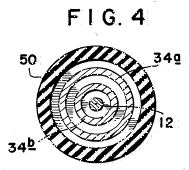
Figure 5 is a schematic circuit diagram of the alternating-current input circuit.
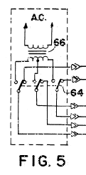
Description of the Preferred Embodiment ~
While the present invention is susceptible of various modifications and alternative constructions, an embodiment is shown in the drawings and will herein be described in detail. It should be understood however that it is not the intention to limit the invention to the particular form disclosed; but, on the contrary, the invention is to cover all modifications, equivalents and alternative constructions falling within the spirit and scope of the invention as expressed in the appended claims.
There is disclosed herein an electrical driving system which, on theory, will convert low voltage electric energy from a source such as an electric storage battery to a high potential, high current energy pulse that is capable of developing a working force at the inductive output of the device that is more efficient than that which is capable of being developed directly from the energy source. The improvement in efficiency is further enhanced by the capability of the device to return that portion of the initial energy developed, and not used by the inductive load in the production of mechanical energy, to the same or second energy reservoir or source for use elsewhere, or for storage.
This system accomplishes the results stated above by harnessing the "electrostatic" or "impulse" energy created by a high-intensity spark generated within a specially constructed electrical conversion switching element tube. This element utilizes a low-voltage anode, a high-voltage anode, and one or more "electrostatic" or charge receiving grids. These grids are of a physical size, and appropriately positioned, as to be compatible with the size of the tube, and therefore, directly related to the amount of energy to be anticipated when the device is operating.
The low-voltage anode may incorporate a resistive device to aid in controlling the amount of current drawn from the energy source. This low-voltage anode is connected to the energy source through a mechanical commutator or a solid-state pulser that controls the timing and duration of the energy spark within the element. The high-voltage anode is connected to a high-voltage potential developed by the associated circuits. An energy discharge occurs within the element when the external control circuits permit. This short duration, high-voltage, high-current energy pulse is captured by the "electrostatic" grids within the tube, stored momentarily, then transferred to the inductive output load.
The increase in efficiency anticipated in converting the electrical energy to mechanical energy within the inductive load is attributed to the utilization of the most optimum timing in introducing the electrical energy to the load device, for the optimum period of time.
Further enhancement of energy conservation is accomplished by capturing a significant portion of the energy generated by the inductive load when the useful energy field is collapsing. This energy is normally dissipated in load losses that are contrary to the desired energy utilization, and have heretofore been accepted because no suitable means had been developed to harness this energy and restore it to a suitable energy storage device.
The present invention is concerned with two concepts or characteristics. The first of these characteristics is observed with the introduction of an energizing current through the inductor. The inductor creates a contrary force (counter-electromotive force or CEMF) that opposes the energy introduced into the inductor. This CEMF increases throughout the time the introduced energy is increasing.
In normal applications of an alternating-current to an inductive load for mechanical applications, the useful work of the inductor is accomplished prior to terminating the application of energy. The excess energy applied is thereby wasted.
Previous attempts to provide energy inputs to an inductor of time durations limited to that period when the optimum transfer of inductive energy to mechanical energy is occurring, have been limited by the ability of any such device to handle the high current required to optimize the energy transfer.
The second characteristic is observed when the energizing current is removed from the inductor. As the current is decreased, the inductor generates an EMF that opposes the removal of current or, in other words, produces an energy source at the output of the inductor that simulates the original energy source, reduced by the actual energy removed from the circuit by the mechanical load. This "regenerated", or excess, energy has previously been lost due to a failure to provide a storage capability for this energy.
In this invention, a high-voltage, high-current, short duration energy pulse is applied to the inductive load by the conversion element. This element makes possible the use of certain of that energy impressed within an arc across a spark-gap, without the resultant deterioration of circuit elements normally associated with high energy electrical arcs.
This invention also provides for capture of a certain portion of the energy induced by the high inductive kick produced by the abrupt withdrawal of the introduced current. This abrupt withdrawal of current is attendant upon the termination of the stimulating arc. The voltage spike so created is imposed upon a capacitor that couples the attendant current to a secondary energy storage device.
A novel, but not essential, circuit arrangement provides for switching the energy source and the energy storage device. This switching may be so arranged as to actuate automatically at predetermined times. The switching may be at specified periods determined by experimentation with a particular device, or may be actuated by some control device that measures the relative energy content of the two energy reservoirs.
Referring now to Figure 1, the system 10 will be described in additional detail. The potential for the high-voltage anode, 12 of the conversion element 14 is developed across the capacitor 16. This voltage is produced by drawing a low current from a battery source 18 through the vibrator 20. The effect of the vibrator is to create a pulsating input to the transformer 22. The turns ratio of the transformer is chosen to optimize the voltage applied to a bridge-type rectifier 24. The output of the rectifier is then a series of high-voltage pulses of modest current. When the available source is already of the high voltage, AC type, it may be coupled directly to the bridge-type rectifier.
By repetitious application of these output pulses from the bridge-type rectifier to the capacitor 16, a high-voltage, high-level charge is built up on the capacitor.
Control of the conversion switching element tube is maintained by a commutator 26. A series of contacts mounted radially about a shaft, or a solid-state switching device sensitive to time or other variable may be used for this control element. A switching element tube type one-way energy path 28 is introduced between the commutator device and the conversion switching element tube to prevent high energy arcing at the commutator current path. When the switching element tube is closed, current from the voltage source 18 is routed through a resistive element 30 and a low voltage anode 32. This causes a high energy discharge between the anodes within the conversion switching element tube 14.
The energy content of the high energy pulse is electrostatically coupled to the conversion grids 34 of the conversion element. This electrostatic charge is applied through an output terminal 60 (Figure 2) across the load inductance 36, inducing a strong electromagnetic field about the inductive load. The intensity of this electromagnetic field is determined by the high electromotive potential developed upon the electrostatic grids and the very short time duration required to develop the energy pulse.
If the inductive load is coupled magnetically to a mechanical load, a strong initial torque is developed that may be efficiently utilized to produce physical work.
Upon cessation of the energy pulse (arc) within the conversion switching element tube the inductive load is decoupled, allowing the electromagnetic field about the inductive load to collapse. The collapse of this energy field induces within the inductive load a counter EMF. This counter EMF creates a high positive potential across a second capacitor which, in turn, is induced into the second energy storage device or battery 40 as a charging current. The amount of charging current available to the battery 40 is dependent upon the initial conditions within the circuit at the time of discharge within the conversion switching element tube and the amount of mechanical energy consumed by the work load.
A spark-gap protection device 42 is included in the circuit to protect the inductive load and the rectifier elements from unduly large discharge currents. Should the potentials within the circuit exceed predetermined values, fixed by the mechanical size and spacing of the elements within the protective device, the excess energy is dissipated (bypassed) by the protective device to the circuit common (electrical ground).
Diodes 44 and 46 bypass the excess overshoot generated when the "Energy Conversion Switching Element Tube" is triggered.
A switching element 48 allows either energy storage source to be used as the primary energy source, while the other battery is used as the energy retrieval unit. The switch facilitates interchanging the source and the retrieval unit at optimum intervals to be determined by the utilization of the conversion switching element tube. This switching may be accomplished manually or automatically, as determined by the choice of switching element from among a large variety readily available for the purpose.
Figure 2, 3, and 4 show the mechanical structure of the conversion switching element tube 14. An outer housing 50 may be of any insulative material such as glass. The anodes 12 and 22 and grids 34a and 34b are firmly secured by nonconductive spacer material 54, and 56. The resistive element 30 may be introduced into the low-voltage anode path to control the peak currents through the conversion switching element tube. The resistive element may be of a piece, or it may be built of one or more resistive elements to achieve the desired result.
The anode material may be identical for each anode, or may be of differing materials for each anode, as dictated by the most efficient utilization of the device, as determined by appropriate research at the time of production for the intended use.
The shape and spacing of the electrostatic grids is also susceptible to variation with application (voltage, current, and energy requirements).
It is the contention of the inventor that by judicious mating of the elements of the conversion switching element tube, and the proper selection of the components of the circuit elements of the system, the desired theoretical results may be achieved. It is the inventor's contention that this mating and selection process is well within the capabilities of intensive research and development technique.
Let it be stated here that substituting a source of electric alternating-current subject to the required current and/or voltage shaping and/or timing, either prior to being considered a primary energy source, or thereafter, should not be construed to change the described utilization or application of primary energy in any way. Such energy conversion is readily achieved by any of a multitude of well established principles. The preferred embodiment of this invention merely assumes optimum utilization and optimum benefit from this invention when used with portable energy devices similar in principle to the wet-cell or dry-cell battery.
This invention proposes to utilize the energy contained in an internally generated high-voltage electric spike (energy pulse) to electrically energize an inductive load; this inductive load being then capable of converting the energy so supplied into a usefu1 electrical or mechanical output.
In operation the high-voltage, short-duration electric spike is generated by discharging the capacitor 16 across the spark-gap in the conversion switching element tube. The necessary high-voltage potential is stored on the capacitor in incremental, additive steps from the bridge-type rectifier 24.
When the energy source is a direct-current electric energy storage device, such as the battery 12, the input to the bridge rectifier is provided by the voltage step-up transformer 22, that is in turn energized from the vibrator 20, or solid-state chopper, or similar device to properly drive the transformer and rectifier circuits.
When the energy source is an alternating-current, switches 64 disconnect transformer 22 and the input to the bridge-type rectifier 24 is provided by the voltage step-up transformer 66, that is in turn energized from the vibrator 20, or solid-state chopper, or similar device to properly drive the transformer and rectifier circuits.
The repetitions output of the bridge rectifier incrementally increases the capacitor charge toward its maximum. This charge is electrically connected directly to the high-voltage anode 12 of the conversion switching element tube.
When the low-voltage anode 32 is connected to a source of current, an arc is created in the spark-gap designated 62 of the conversion switching element tube equivalent to the potential stored on the high-voltage anode, and the current available from the low-voltage anode. Because the duration of the arc is very short, the instantaneous voltage, and instantaneous current may both be very high. The instantaneous peak apparent power is therefore, also very high. Within the conversion switching element tube, this energy is absorbed by the grids 34a and 34b mounted circumferentially about the interior of the tube.
Control of the energy spike within the conversion switching element tube is accomplished by a mechanical, or solid-state commutator, that closes the circuit path from the low-voltage anode to the current source at that moment when the delivery of energy to the output load is most auspicious. Any number of standard high-accuracy, variable setting devices are available for this purpose. When control of the repetitive rate of the system's output is required, it is accomplished by controlling the time of connection at the low-voltage anode.
Thus there can be provided an electrical driving system having a low-voltage source coupled to a vibrator, a transformer and a bridge-type rectifier to provide a high voltage pulsating signal to a first capacitor. Where a high-voltage source is otherwise available, it may be coupled direct to a bridge-type rectifier, causing a pulsating signal to a first capacitor. The capacitor in turn is coupled to a high-voltage anode of an electrical conversion switching element tube. The element also includes a low-voltage anode which in turn is connected to a voltage source by a commutator, a switching element tube, and a variable resistor.
Mounted around the high-voltage anode is a charge receiving plate which in turn is coupled to an inductive load to transmit a high-voltage discharge from the element to the load. Also coupled to the load is a second capacitor for storing the back EMF created by the collapsing electrical field of the load when the current to the load is blocked. The second capacitor in turn is coupled to the voltage source.
Claims ~
What is claimed is:
1. An electrical driving system comprising: a source of electrical voltage; a vibrator connected to said source for forming a pulsating signal; a transformer connected to said vibrator for receiving said pulsating signal; a rectifier connected to said transformer having a high-voltage pulse output; a capacitor for receiving said voltage pulse output; a conversion switching element tube having first and second anodes, electrically conductive means for receiving a charge positioned about said second anode and an output terminal connected to said charge receiving means, said second anode being connected to said capacitor; a commutator connected to said source of electrical voltage and to said first anode; and an inductive load connected to said output terminal whereby a high energy discharge between said first and second anodes is transferred to said charge receiving means and then to said inductive load.
2. A system as claimed in claim 1, including a second capacitor for receiving a charge from said load.
3. A system as claimed in claim 2, including a switching element tube positioned in series between said commutator and said first anode.
4. A system as claimed in claim 3, including a second source of voltage and a switch for receiving a signal from said second capacitor.
5. A system as claimed in claim 4 wherein: said conversion switching element tube includes a resistive element in series with said first anode; and said charge receiving means is tubularly shaped.
6. A system as in claim 1 wherein said source comprises a direct current source and wherein said system further comprises:a source of alternating current; and a switch means for selecting said direct-current or said alternating-current power source as input to said rectifier.
7. A system as in claim 1 wherein said rectifier comprises a bridge-type rectifier.
8. A method for providing power to an inductive load comprising the steps of providing a voltage source; pulsating a signal from said source; increasing the voltage of said signal; rectifying said signal; storing and increasing said signal; conducting said signal to a high-voltage anode; providing a low-voltage to a second anode to form a high energy discharge; electrostatically coupling said discharge to a charge receiving element; conducting said discharge to an inductive load; coupling a second capacitor to said load; and coupling said capacitor to said source.
US Patent # 4,661,747
Efficient Electrical Conversion Switching Tube Suitable for Inductive Loads
( Cl. 315/30 ~ April 28, 1987 )
Edwin V.Gray, Sr.
Abstract ~
Disclosed is an electrical driving and recovery system for a high frequency environment. The recovery system can be applied to drive present day direct-current or alternating-current loads for better efficiency. It has a low-voltage source coupled to a vibrator, a transformer and a bridge-type rectifier to provide a high voltage pulsating signal to a first capacitor. Where a high-voltage source is otherwise available, it may be coupled directly to a bridge-type rectifier, causing a pulsating signal to the first capacitor. The first capacitor in turn is coupled to a high voltage anode of an electrical conversion switching element tube. The switching element tube also includes a low voltage anode which is connected to a voltage source by a commutator and a switching element tube. Mounted around the high voltage anode is a charge receiving plate which is coupled to an inductive load to transmit a high voltage discharge from the switching element tube to the load. Also coupled to the load is a second capacitor for storing the back EMF created by the collapsing electrical field of the load when the current to the load is blocked. The second capacitor is coupled to the voltage source. When adapted to present day direct-current or alternating-current devices the load could be a battery or capacitor to enhance the productivity of electrical energy.
Inventors: Gray, Sr.; Edwin V.
(P.O. Box 362, Council, ID 83612)
Appl. No.: 791508 ~ Filed: October
25, 1985
Foreign Application Priority Data: Dec 16, 1983[GR] 124388
Current U.S. Class: 315/330; 313/601;
313/602; 313/604; 315/261; 315/335
Intern'l Class: H01J 011/04; H01J 013/48;
H05B 037/00; H05B 039/00
Field
of Search: 315/57,58,60,36,334,335,330,336,261
313/595,601,602,603
References Cited:
U.S. Patent Documents:
3,443,142 (May 1969) Koppl, et al.
(315/58.)
3,663,855 (May 1972)
Boettcher (315/330)
3,798,461
(Mar. 1974) Edson (315/36)
3,939,379 (Feb. 1976) Sullivan, et al.
(315/330)
4,198,590 (Apr. 1980)
Harris (315/335)
4,370,597 (Jan.
1983) Weiner, et al. (315/58)
Foreign Patent Documents
0540,361 (Dec. 1976) SU 315/335.
Primary Examiner: Chatmon; Saxfield
This is a division of application Ser. No. 662,339, filed Oct. 18, 1984, now U.S. Pat. No. 4,595,975.
Description ~
Background of the Invention
1. Field of the Invention:
The present invention relates to an electrical driving system and a conversion element, and more particularly, to a system for driving an inductive load in a greatly improved and efficient manner.
2. Description of the Prior Act:
In the opinion of the inventor, there is no known device which provides the conversion of energy from a direct-current electric source or an alternating-current electric source to a mechanical force based on the principle of this invention. EXAMPLE: A portable energy source, (1) such as a battery, (2) such as alternating-current, (3) such as the combination of battery and alternating-current, may be used with highly improved efficiency to operate a mechanical device, whose output is a linear or rotary force, with an attendant increase in the useful productive period between external applications of energy restoration for the energy source.
Summary of the Invention ~
The present invention provides a more efficient driving system comprising a source of electrical voltage; a vibrator connected to the low-voltage source for forming a pulsating signal; a transformer connected to the vibrator for receiving the pulsating signal; a high-voltage source, where available, connected to a bridge-type rectifier; or the bridge-type rectifier connected to the high voltage pulse output of the transformer; a capacitor for receiving the voltage pulse output; a conversion element having first and second anodes, electrically conductive means for receiving a charge positioned about the second anode and an output terminal connected to the charge receiving means, the second anode being connected to the capacitor; a commutator connected to the source of electrical voltage and to the first anode; and an inductive load connected to the output terminal whereby a high energy discharge between the first and second anodes is transferred to the charge receiving means and then to the inductive load.
As a sub-combination, the present invention also includes a conversion element comprising a housing; a first low voltage anode mounted to the housing, the first anode adapted to be connected to a voltage source; a second high voltage anode mounted to the housing, the second anode adapted to be connected to a voltage source; electrically conductive means positioned about the second anode and spaced therefrom for receiving a charge, the charge receiving means being mounted to the housing; and an output terminal communicating with the charge receiving means, said terminal adapted to be connected to an inductive load.
The invention also includes a method for providing power to an inductive load comprising the steps of providing a voltage source, pulsating a signal from said source; increasing the voltage of said signal; rectifying said signal; storing and increasing the signal; conducting said signal to a high voltage anode; providing a low voltage to a second anode to form a high energy discharge; electrostatically coupling the discharge to a charge receiving element; conducting the discharge to an inductive load; coupling a second capacitor to the load; and coupling the second capacitor to the source.
It is an aim of the present invention to provide a system for driving an inductive load which system is substantially more efficient than any now existing.
Another object of the present invention is to provide a system for driving an inductive load which is reliable, is inexpensive and simply constructed .
The foregoing objects of the present invention together with various other objects, advantages, features and results thereof which will be evident to those skilled in the art in light of this disclosure may be achieved with the exemplary embodiment of the invention described in detail hereinafter and illustrated in the accompanying drawings.
Brief Description of the Drawings ~
Figure 1 is a schematic circuit diagram of the electrical driving system.
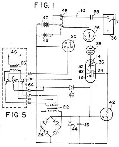
Figure 2 is an elevational sectional view of the electrical conversion element.
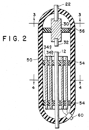
Figure 3 is a plan sectional view taken along line 3--3 of Figure 2.
Figure 4 is a plan sectional view taken along line 4--4 of Figure 2.
Figure 5 is a schematic circuit diagram of the alternating-current input circuit.
Description of the Preferred Embodiment ~
While the present invention is susceptible of various modifications and alternative constructions, an embodiment is shown in the drawings and will herein be described in detail. It should be understood however that it is not the intention to limit the invention to the particular form disclosed; but, on the contrary, the invention is to cover all modifications, equivalents and alternative constructions falling within the spirit and scope of the invention as expressed in the appended claims.
There is disclosed herein an electrical driving system which, on theory, will convert low voltage electric energy from a source such as an electric storage battery to a high potential, high current energy pulse that is capable of developing a working force at the inductive output of the device that is more efficient than that which is capable of being developed directly from the energy source. The improvement in efficiency is further enhanced by the capability of the device to return that portion of the initial energy developed, and not used by the inductive load in the production of mechanical energy, to the same or second energy reservoir or source for use elsewhere, or for storage.
This system accomplishes the results stated above by harnessing the "electrostatic" or "impulse" energy created by a high-intensity spark generated within a specially constructed electrical conversion switching element tube. This element utilizes a low-voltage anode, a high-voltage anode, and one or more "electrostatic" or charge receiving grids. These grids are of a physical size, and appropriately positioned, as to be compatible with the size of the tube, and therefore, directly related to the amount of energy to be anticipated when the device is operating.
The low-voltage anode may incorporate a resistive device to aid in controlling the amount of current drawn from the energy source. This low-voltage anode is connected to the energy source through a mechanical commutator or a solid-state pulser that controls the timing and duration of the energy spark within the element. The high-voltage anode is connected to a high-voltage potential developed by the associated circuits. An energy discharge occurs within the element when the external control circuits permit. This short duration, high-voltage, high-current energy pulse is captured by the "electrostatic" grids within the tube, stored momentarily, then transferred to the inductive output load.
The increase in efficiency anticipated in converting the electrical energy to mechanical energy within the inductive load is attributed to the utilization of the most optimum timing in introducing the electrical energy to the load device, for the optimum period of time.
Further enhancement of energy conservation is accomplished by capturing a significant portion of the energy generated by the inductive load when the useful energy field is collapsing. This energy is normally dissipated in load losses that are contrary to the desired energy utilization, and have heretofore been accepted because no suitable means had been developed to harness this energy and restore it to a suitable energy storage device.
The present invention is concerned with two concepts or characteristics. The first of these characteristics is observed with the introduction of an energizing current through the inductor. The inductor creates a contrary force (counter-electromotive force or CEMF) that opposes the energy introduced into the inductor. This CEMF increases throughout the time the introduced energy is increasing.
In normal applications of an alternating-current to an inductive load for mechanical applications, the useful work of the inductor is accomplished prior to terminating the application of energy. The excess energy applied is thereby wasted.
Previous attempts to provide energy inputs to an inductor of time durations limited to that period when the optimum transfer of inductive energy to mechanical energy is occurring, have been limited by the ability of any such device to handle the high current required to optimize the energy transfer.
The second characteristic is observed when the energizing current is removed from the inductor. As the current is decreased, the inductor generates an EMF that opposes the removal of current or, in other words, produces an energy source at the output of the inductor that simulates the original energy source, reduced by the actual energy removed from the circuit by the mechanical load. This "regenerated", or excess, energy has previously been lost due to a failure to provide a storage capability for this energy.
In this invention, a high-voltage, high-current, short duration energy pulse is applied to the inductive load by the conversion element. This element makes possible the use of certain of that energy impressed within an arc across a spark-gap, without the resultant deterioration of circuit elements normally associated with high energy electrical arcs.
This invention also provides for capture of a certain portion of the energy induced by the high inductive kick produced by the abrupt withdrawal of the introduced current. This abrupt withdrawal of current is attendant upon the termination of the stimulating arc. The voltage spike so created is imposed upon a capacitor that couples the attendant current to a secondary energy storage device.
A novel, but not essential, circuit arrangement provides for switching the energy source and the energy storage device. This switching may be so arranged as to actuate automatically at predetermined times. The switching may be at specified periods determined by experimentation with a particular device, or may be actuated by some control device that measures the relative energy content of the two energy reservoirs.
Referring now to Figure 1, the system 10 will be described in additional detail. The potential for the high-voltage anode 12 of the conversion element 14 is developed across the capacitor 16. This voltage is produced by drawing a low current from a battery source 18 through the vibrator 20. The effect of the vibrator is to create a pulsating input to the transformer 22. The turns ratio of the transformer is chosen to optimize the voltage applied to a bridge-type rectifier 24. The output of the rectifier is then a series of high-voltage pulses of modest current. When the available source is already of the high voltage AC type, it may be coupled directly to the bridge-type rectifier.
By repetitious application of these output pulses from the bridge-type rectifier to the capacitor 16, a high-voltage high-level charge is built up on the capacitor.
Control of the conversion switching element tube is maintained by a commutator 26. A series of contacts mounted radially about a shaft, or a solid-state switching device sensitive to time or other variable may be used for this control element. A switching element tube type one-way energy path 28 is introduced between the commutator device and the conversion switching element tube to prevent high energy arcing at the commutator current path. When the switching element tube is closed, current from the voltage source 18 is routed through a resistive element 30 and a low voltage anode 32. This causes a high energy discharge between the anodes within the conversion switching element tube 14.
The energy content of the high energy pulse is electrostatically coupled to the conversion grids 34 of the conversion element. This electrostatic charge is applied through an output terminal 60 (Figure 2) across the load inductance 36, inducing a strong electromagnetic field about the inductive load. The intensity of this electromagnetic field is determined by the high electromotive potential developed upon the electrostatic grids and the very short time duration required to develop the energy pulse.
If the inductive load is coupled magnetically to a mechanical load, a strong initial torque is developed that may be efficiently utilized to produce physical work.
Upon cessation of the energy pulse (arc) within the conversion switching element tube the inductive load is decoupled, allowing the electromagnetic field about the inductive load to collapse. The collapse of this energy field induces within the inductive load a counter EMF. This counter EMF creates a high positive potential across a second capacitor 38 which, in turn, is induced into the second energy storage device or battery 40 as a charging current. The amount of charging current available to the battery 40 is dependent upon the initial conditions within the circuit at the time of discharge within the conversion switching element tube and the amount of mechanical energy consumed by the work load.
A spark-gap protection device 42 is included in the circuit to protect the inductive load and the rectifier elements from unduly large discharge currents. Should the potentials within the circuit exceed predetermined values, fixed by the mechanical size and spacing of the elements within the protective device, the excess energy is dissipated (bypassed) by the protective device to the circuit common (electrical ground).
Diodes 44 and 46 bypass the excess overshoot generated when the "Energy Conversion Switching Element Tube" is triggered.
A switching element 48 allows either energy storage source to be used as the primary energy source, while the other battery is used as the energy retrieval unit. The switch facilitates interchanging the source and the retrieval unit at optimum intervals to be determined by the utilization of the conversion switching element tube. This switching may be accomplished manually or automatically, as determined by the choice of switching element from among a large variety readily available for the purpose.
Figures 2, 3, and 4 show the mechanical structure of the conversion switching element tube 14. An outer housing 50 may be of any insulative material such as glass. The anodes 12 and 32 and grids 34a and 34b are firmly secured by nonconductive spacer material 54, and 56. The resistive element 30 may be introduced into the low-voltage anode path to control the peak currents through the conversion switching element tube. The resistive element may be of a piece, or it may be built of one or more resistive elements to achieve the desired result.
The anode material may be identical for each anode, or may be of differing materials for each anode, as dictated by the most efficient utilization of the device, as determined by appropriate research at the time of production for the intended use.
The shape and spacing of the electrostatic grids is also susceptible to variation with application (voltage, current, and energy requirements).
It is the contention of the inventor that by judicious mating of the elements of the conversion switching element tube, and the proper selection of the components of the circuit elements of the system, the desired theoretical results may be achieved. It is the inventor's contention that this mating and selection process is well within the capabilities of intensive research and development technique.
Let it be stated here that substituting a source of electric alternating-current subject to the required current and/or voltage shaping and/or timing, either prior to being considered a primary energy source, or thereafter, should not be construed to change the described utilization or application of primary energy in any way. Such energy conversion is readily achieved by any of a multitude of well established principles. The preferred embodiment of this invention merely assumes optimum utilization and optimum benefit from this invention when used with portable energy devices similar in principle to the wet-cell or dry-cell battery.
This invention proposes to utilize the energy contained in an internally generated high-voltage electric spike (energy pulse) to electrically energize an inductive load; this inductive load being then capable of converting the energy so supplied into a useful electrical or mechanical output. In operation the high-voltage, short-duration electric spike is generated by discharging the capacitor 16 across the spark-gap in the conversion switching element tube. The necessary high-voltage potential is stored on the capacitor in incremental, additive steps from the bridge-type rectifier 24.
When the energy source is a direct-current electric energy storage device, such as the battery 12, the input to the bridge rectifier is provided by the voltage step-up transformer 22, that is in turn energized from the vibrator 20, or solid-state chopper, or similar device to properly drive the transformer and rectifier circuits.
When the energy source is an alternating-current, switches 64 disconnect transformer 22 and the input to the bridge-type rectifier 24 is provided by the voltage step-up transformer 66, that is in turn energized from the vibrator 20, or solid-state chopper, or similar device to properly drive the transformer and rectifier circuits.
The repetitious output of the bridge rectifier incrementally increases the capacitor charge toward its maximum. This charge is electrically connected directly to the high-voltage anode 12 of the conversion switching element tube.
When the low-voltage anode 32 is connected to a source of current, an arc is created in the spark-gap designated 62 of the conversion switching element tube equivalent to the potential stored on the high-voltage anode, and the current available from the low-voltage anode. Because the duration of the arc is very short, the instantaneous voltage, and instantaneous current may both be very high. The instantaneous peak apparent power is therefore, also very high. Within the conversion switching element tube, this energy is absorbed by the grids 34a and 34b mounted circumferentially about the interior of the tube.
Control of the energy spike within the conversion switching element tube is accomplished by a mechanical, or solid-state commutator, that closes the circuit path from the low-voltage anode to the current source at that moment when the delivery of energy to the output load is most auspicious. Any number of standard high-accuracy, variable setting devices are available for this purpose. When control of the repetitive rate of the system's output is required, it is accomplished by controlling the time of connection at the low-voltage anode.
Thus there can be provided an electrical driving system having a low-voltage source coupled to a vibrator, a transformer and a bridge-type rectifier to provide a high voltage pulsating signal to a first capacitor. Where a high-voltage source is otherwise available, it may be coupled direct to a bridge-type rectifier, causing a pulsating signal to a first capacitor. The capacitor in turn is coupled to a high-voltage anode of an electrical conversion switching element tube. The element also includes a low-voltage anode which in turn is connected to a voltage source by a commutator, a switching element tube, and a variable resistor.
Mounted around the high-voltage anode is a charge receiving plate which in turn is coupled to an inductive load to transmit a high-voltage discharge from the element to the load. Also coupled to the load is a second capacitor for storing the back EMF created by the collapsing electrical field of the load when the current to the load is blocked. The second capacitor in turn is coupled to the voltage source.
Claims ~
What is claimed is:
1. An electrical conversion switching element tube comprising: a closed insulative housing (50); a first low-voltage anode (32) mounted internally to said housing and extending internally to an electrical discharge area (62), said first anode adapted to be connected to a voltage source external to the housing; a second high-voltage anode (12) mounted internally to said housing and extending internally to said electrical discharge area (62), said second anode also being adapted to be connected to a voltage source external to the housing; electrically conductive means (34b) positioned internally within said housing and extending circumferentially about said second anode while being directly exposed thereto but not conductively connected thereto but, rather, spaced therefrom for receiving an electrostatic charge from the second anode when a discharge current is triggered across said discharge area between said first and second anodes, said charge receiving electrically conductive means also being internally mounted to said housing; and an output terminal (60) communicating with said charge receiving electrically conductive means, said terminal adapted to be connected to an inductive load externally of said housing.
2. An electrical conversion switching element tube as claimed in claim 1, including a resistive element (30) in series with said first anode.
3. An electrical conversion switching element tube as claimed in claim 1 wherein: said charge receiving electrically conductive means is tubularly shaped.
4. An electrical conversion switching element tube as claimed in claim 3, including a second tubularly shaped charge receiving electrically conductive means (34a) positioned circumferentially about said first mentioned charge receiving electrically conductive means.
For more information (photos, schematics, videos, books, R&D, &c.), visit Peter Lindemann's website:
http://www.free-energy.cc
Clear Tech, Inc. ~
P.O.Box 37, Metline Falls, WA 99153 USA
Phome: (509) 446-2353 ~ Fax: (509)
446-2354
Order Line Only:
1-888-260-2770
"The Free Energy
Secrets of Cold Electricity"
by Peter A. Lindemann,
D.Sc.
VIDEO ~ In the 1970's, inventor Edwin Gray developed an electric automobile engine that produced 80 horsepower and recharged its own batteries. It ran on what he called "cold electricity." This amazing technology remained shrouded in mystery until September 2000. This three-part video is the complete technical lecture given by Dr. Lindemann at that time. In it, he explains exactly how Ed Gray's system works, how he produced "cold electricity" and how that relates to Nikola Tesla's earlier discovery of "Radiant Energy". Using 50 slides of articles, patents, photos, and circuit diagrams, Dr. Lindemann documents his research, until the method is fully revealed. Now you can understand one of the most powerful Free Energy methods ever discovered.
"The Free Energy
Secrets of Cold Electricity "
by Peter A. Lindemann,
D.Sc.
BOOK ~ This book covers the same information as the video by this title. It explains how Edwin Gray produced "cold electricity" and how that relates to Nikola Tesla's discovery of "Radiant Energy" over a century ago. All of the images that appear as slides in the video are reproduced in the book, as well as complete reprints of Edwin Gray's three US patents, and three of Nikola Tesla's US Patents, which related to the subject. This is an important study manual for serious researchers. Ed Gray's EMA motor produced 40 times more power than he took from batteries. The secret is in the power supply and this book tells how he did it!
"The History of The
E.V. Gray Motor "
by Norman Wootan
VIDEO ~ The truth is finally revealed. The mystery about Ed Gray's EMA motors is finally over. With two recovered EMA motor prototypes on stage at the KeelyNet Conference in June 2001, Norman Wootan discusses every design feature possible. Every single way the real motors deviate from the designs revealed in Gray's Patent are discussed in detail. Now you can see with your own eyes how it was really done. This video is a must for serious researchers wanting to convert Radiant Energy into mechanical power. A great companion piece to "The Free Energy Secrets of Cold Electricity" by Dr. Lindemann where the EMA power supply is discussed. (2 hrs.)
[Note: These items are not sold by Rex Research. They are available from Clear-Tech, Inc. --- www.free-energy.cc
Regenerative Energy Recovery System, e.g., for Electromagnetic Propulsion
[ Unidentified British Application Number ]
( 10 April 1980 )
Back emf can result in energy loss, or inefficient use of energy, in inductive circuits. A regenerative energy recovery system, embodying the present invention employs switching 6 to discharge a capacitor 3, through an inductive load 5, e.g., a motor. When capacitor 3 is discharged, a diode 4 creates an alternative circuit path through which inductively maintained current may then continue to flow, for example to charge a battery 7. The invention may be of particular value in electromagnetic propulsion systems.
Specification
Background of the Invention
The inventor believes this to be a unique and novel approach to the control of electrical energy for possible future application for the propulsion of inductive devices.
Through the use of certain inductive devices which enables the device to hold for a short period of time discharges of the capacitors to an external inductive load, the back EMF produced is captured and stored for future use. The result, then being, that the inventor believes this to be a more efficient use of energy.
Summary of the Invention
The invention relates to the Regenerative Energy Recovery System designed into a configuration wherein energy is momentarily stored for subsequent release for use in propelling electromagnetic devices.
The Regenerative Energy Recovery System is designed to accept a high potential charge from a capacitor which has been charged from a high voltage power source. When the magnitude has been attained at a high level, this will cause a high current spike which can then be utilized into the inductive load. A part of the EMF, that is normally lost, is recaptured and rerouted and stored for future use.
According to the preferred embodiment of this invention is an energy conserving system. Exemplary embodiments of the invention are herein illustrated. These exemplary illustrations and descriptions should not be construed as limiting the invention to the embodiments shown, because those skilled in the arts appertaining to the invention may conceive of other embodiments in the light of the description.
Description of the Preferred Embodiment
As herein mentioned, the basic principle of the regenerative energy recovery system will be explained using the simplified block diagrams of Figures 1 and 2.
Figure 1 shows all the major and necessary components in simplified block form.
Figure 2 duplicates Figure 1 but is broken into the three sections A, B, and C, corresponding to the three phases of operation of the process which takes place sequentially. The explanation will use Figure 2, but also applies to Figure 1.
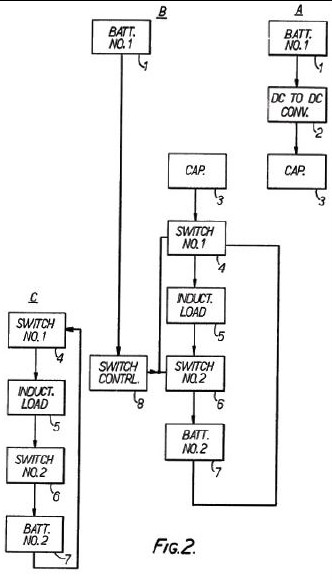
Figure 3 shows an electrical schematic view of the system of Figures 1 and 2.
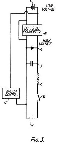
Brief Description of Drawings
During phase A, a capacitor (item 3) is charged to a high voltage of about 2000 volts. Battery No. 1, shown as 24 V (item 1) has its voltage charged to 2000 volts by the use of DC to DC converter (item 2). Item 1 is shown as a battery because that is usually a portable electrical energy source. Item 2 is any means suitable to change a low voltage to a high voltage. The phase A purpose is to obtain a high voltage change in a suitable capacitor.
During phase B, the capacitor (item 3) charged to a high voltage is discharged by closing the normally open (N.O.) switch (item 6). The switch control (item 8) programs when the switches (items 4 and 6) are operated. The discharge current is rapidly p[assed through switch number 1 (item 4), through the inductive load (item 5) and through the now closed switch number 2 (item 6), and through the energy recovery battery number 2 (item 7). Phase B continues until the capacitor approaches zero voltage whereupon the inertia of the current in the inductance of the inductive load would normally start an overshoot of reversed charge into the capacitor.
During phase C, the switch number 1 (item 4) disconnects capacitor 9item 3) without interrupting the current flowing in the path described in phase B. That is, the current path is through items 5, 6, 7, and back through item 4 into the inductive load (item 5) in a closed loop.
Switches, items 4 and 6 are any devices which will perform the desired switching function in the corresponding parts of the circuit.
Inductive loads (item 5) may be a single load, or multiple loads, If a single load, the circuit may be duplicated so two inductive loads can interact in an inductive configuration.
If a single load, a permanent magnetic field may also be used so two interacting magnetic fields can cause force and motion. If multiple loads, one may be designated a rotor load. Suitable polarities will determine whether attractive or repulsive interaction will occur. The timing of the discharge will occur at the instant the loads are properly positioned. The timing of discharge will be determined by the switch control.
Claims [ Not included here ]
Your Support Maintains this Service. Please Invest in the mind-boggling Rex Research Website CD -- Always The Best Investment ... Everything on this Website & More ( the Bonus Files CD ) -- Only $13, Postpaid Anywhere ! Secure Transaction via PayPal: All Major Credit Cards Accepted:
No Credit ? Don't like PayPal ? Send a Check/Money Order to:
Rex Research, PO Box 19250, Jean, NV 89019 USA