| One very interesting feature of
free-energy devices is that although various devices which appear to be
completely different and have different apparent applications, the
background operation is often the same. It is clear that a sharp
positive going DC electric pulse interacts with the surrounding energy
field, making large quantities of free-energy available for anyone who has
the knowledge of how to gather and use that extra energy. Let me stress again that “over-unity” is an impossibility. Over-unity suggests that more energy can be taken out of a system than the total energy which goes into the system. This is not possible as you can’t have more than 100% of anything. However, there is another perfectly valid way of looking at the operation of any system, and that is to rate the output of the system relative to the amount of energy that the user has to put in to make it work. This is called the “Coefficient Of Performance” or “COP” for short. A COP = 1 is when all of the energy put in by the user is returned as useful output. A COP>1 is where more useful energy comes out of the device than the user has to put in. For example, a sailing boat in a good breeze transports people along without the need for the energy of movement to be supplied by the crew. The energy comes from the local environment and while the efficiency is low, the COP is greater than 1. What we are looking for here is not something to tap wind energy, wave energy, sunlight energy, river energy, thermal energy or whatever but instead we want something which can tap the invisible energy field which surrounds us all, namely the “zero-point energy” field. For this, let us look at pulsing circuits used by a wide range of people in a number of apparently quite different devices. An electrical “pulse” is a sudden voltage rise and fall with very sharply rising and falling voltages. However, pulses are seldom generated as isolated events when working with practical devices, so it is probably better to think of a train of pulses, or a “waveform” with very sharp rising and falling edges. These can be called oscillators or signal generators and are so commonplace that we tend not to give them a second thought, but the really important factors for using an oscillator for zero-point energy pick-up is the quality of the signal. Ideally, what is needed cab a perfect square wave with no overshoot, and the voltage level never going below zero volts, or a complex waveform, also with very sharp attack and decay times. These waveforms are a good deal more difficult to generate than you might imagine. Even in these days of sophisticated solid-state electronic devices, the best method of creating a really sharp voltage pulse is still considered to be a spark gap, especially one which has the spark chopped off suddenly by the use of a strong magnetic field at right angles to the spark gap. For an example of this style of operation, consider the following device. Frank Prentice. Electrical Engineer Frank Wyatt Prentice of the USA invented what he described as an ‘Electrical Power Accumulator’ with an output power six times greater than the input power (COP = 6). He was granted US patent 253,765 on 18th September 1923 and which says: My invention relates to improvements in Electrical Power Accumulators, wherein the earth acting as rotor and the surrounding air as a stator, collects the energy thus generated by the earth rotating on its axis, utilises the same for power and other purposes. In the development of my Wireless Train Control System for railways, covered by my United States Letters Patent Number 843,550, I discovered that, with an antennae consisting of one wire of suitable diameter supported by insulating means three to six inches above the ground and extending one half mile, more or less in length, the said antenna being grounded at one end through a spark gap and energised at the other end by a high frequency generator of 500 Watts input power and having a secondary frequency of 500,000 Hz, would produce in the antenna an oscillatory frequency the same as that of the earth currents and thus electrical power from the surrounding media was accumulated along the length of the transmission antenna and with a closed oscillatory loop antenna 18 feet in length run parallel with the transmission antenna at a distance of approximately 20 feet it was possible to obtain by tuning the loop antennae, sufficient power to light to full power, a series bank of fifty 60 watt carbon lamps. Lowering or raising the frequency of 500,000 Hz resulted in diminishing the amount of power received on the 18 foot antenna. Similarly, raising the transmission antenna resulted in a proportionate decrease of power picked up on the receiving antenna and at 6 feet above the earth no power at all was obtainable without a change of potential and frequency. It is the objective of my generic invention to utilise the power generated by the earth as described here, and illustrated in the drawings. The two figures in the drawings illustrate simple and preferred forms of this invention, but I wish it understood that no limitation is necessarily made as to the exact and precise circuits, shapes, positions, and structural details shown here, and that changes, alterations and modifications may be made when desired within the scope of my invention. DESCRIPTION: 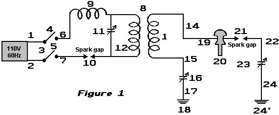 In Fig.1: 1 and 2 are alternating current feed wires supplying 110 volts 60 cycles to a high frequency generator. 3 is a switch with poles 4 and 5. 6 and 7 are connections of high frequency transformer 8 for stepping up the frequency to 500 KHz and the voltage to say 100 KV. 9 is an inductance coil. 10 is a spark gap. 11 is a variable capacitor. 12 is the primary winding of transformer 8. 13 is the secondary winding of transformer 8 which is connected through wire 15 via variable capacitor 16 and wire 17 to ground 18. 14 is the wire from the other side of the secondary winding of transformer 8 connecting it to the main transmission antenna 19 which is supported by insulating means 20. 21 is spark gap from transmission antenna 19 to ground through wire 22, variable capacitor 23, and wire 24 to ground 24'. Transmission antenna 19 may be of any desired length. 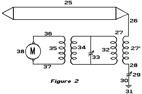 In Fig.2: 25 is a closed oscillating loop antenna of any desired length, which for greatest efficiency, is run parallel with transmission antenna 19 of Fig.1. 26 is the connecting lead between the antenna and step-down transformer 27 of which 27' is the secondary. 28 is the lead connecting the secondary winding 27’ to ground 31 via variable capacitor 29 and lead 30. 32 is the primary winding of transformer 27. 33 is a variable capacitor. 34 and 35 are frequency transformer windings, supplying current through leads 36 and 37 to motor 38, or any other power devices. OPERATION OF THE INVENTION: Close switch 3 to connect feed wires 1 and 2 to transformer leads The high frequency current of 500 KHz returns through the ground, to ground connection 18, up lead 17 to the variable capacitor 16 and via lead 15 to the secondary winding 13 of transformer 8 of Fig.1. The alternating current produced by the 100 KV 500 KHz supply is the same frequency as the earth generated currents, and being in tune with them it picks up additional power from them. Being the same frequency as the output from transformer 8 along wires 14, this produces a reservoir of high frequency current which can be drawn upon by a tuned circuit of the same 500 KHz frequency, as shown in Fig.2. Antenna 25 is tuned to receive a frequency of 500 KHz which produces a current that passes to lead 26 through winding 27' of transformer 27, through wire 28, variable capacitor 29 and wire 30 to ground connection 31. The high frequency currents of 500 KHz pass through to winding 32 and by variable capacitor 33 and windings 34 and 35 of the frequency transformer 27 are stepped down to a voltage and frequency suitable to operate motor 38 via leads 36 and 37. This makes available a current supply for any purpose whatsoever, such as the operation of aeroplanes, cars, railway trains, industrial plants, lighting, heating etc. The return of current through the earth from transmission antenna 14 is preferable to a metallic return as a higher percentage of accumulation of earth currents is noticeable on receiving antennae of Fig.2 than from a metallic return, caused by the capacitance of the grounded circuit. I also prefer under certain conditions to use a single antenna receiving wire in place of the closed loop shown in Fig.2. Under certain operation requirements I have found it expedient to have the transmission antenna elevated and carried on poles many feet above the earth and in that case a different voltage and frequency were found to be necessary to accumulate earth currents along the transmission antenna 14. This system of Frank’s effectively applies very sharply pulsed DC pulses to a long length of wire supported in a horizontal position not far above the ground. The pulses are sharp due to both the spark gap on the primary side of the transformer, along with the spark-gap on the secondary (high voltage) side of the transformer. An input power of 500 watts gives a 3 kW power output from what appears to be an incredibly simple piece of equipment. Dave Lawton. A solid-state semiconductor circuit which has proved successful in producing pulses like this is shown as part of Dave Lawton’s replication of Stan Meyer’s Water Fuel Cell. Here, an ordinary NE555 timer chip generates a square wave which feeds a carefully chosen Field-Effect Transistor the BUZ350 which drives a water-splitter cell via a combined pair of choke coils at point “A” in the diagram below. Stan Meyer used a toroidal ferrite ring when he was winding these choke coils while Dave Lawton uses two straight ferrite bars, bridged top and bottom with thick iron strips. Chokes wound on straight ferrite rods have been found to work very well also. The effects are the same in all cases, with the waveform applied to the pipe electrodes being converted into very sharp, very short, high-voltage spikes. These spikes unbalance the local quantum environment causing vast flows of energy, a tiny percentage of which happens to flow into the circuit as additional power. The cell runs cold, and at low input current, quite unlike an ordinary electrolysis cell where the temperature rises noticeably and the input current needed is much higher. 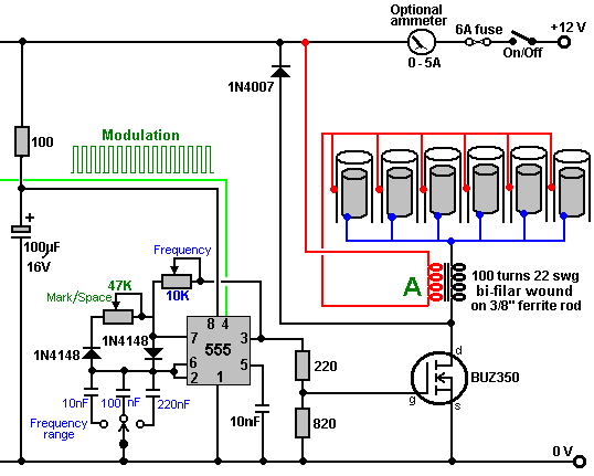 John Bedini uses this same pulsing of a bi-filar wound coil to produce the same very short, very sharp voltage spikes which unbalance the local energy field, causing major flows of additional energy. The figure shown here is from his US patent 6,545,444. 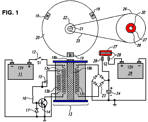 John has produced and generously shared, many designs, all of which are basically similar and all using a 1:1 ratio bi-filar wound transformer. This one uses a free-running rotor with permanent magnets embedded in it’s rim, to trigger sharp induced currents in the windings of the coil unit marked “13b” which switches the transistor on, powering winding “13a” which powers the rotor on its way. The pick-up coil “13c” collects additional energy from the local environment, and in this particular circuit, feeds it into the capacitor. After a few turns of the rotor (dictated by the gear-down ratio to the second rotor), the charge in the capacitor is fed into a second “on-charge” battery. 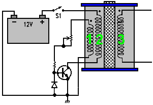 The rotor is desirable but not essential as the coils marked 1 and 2 can self-oscillate, and there can be any number of windings shown as 3 in the diagram. Winding 3 produces very short, sharp, high-voltage spikes, which is the essential part of the design. If those sharp pulses are fed to a lead-acid battery (instead of to a capacitor as shown above), then an unusual effect is created which triggers a link between the battery and the immediate environment, causing the environment to charge the battery. This is an amazing discovery and because the voltage pulses are high-voltage courtesy of the 1:1 choke coils, the battery bank being charged can have any number of batteries and can be stacked as a 24-volt bank even though the driving battery is only 12 volts. Even more interesting is the fact that charging can continue for more than half an hour after the pulsing circuit is switched off. It can be tricky to get one of these circuits tuned properly to work at peak performance, but when they are, they can have performances of COP>10. The major snag is that the charging mechanism does not allow a load to be driven from the battery bank while it is being charged. This means that for any continuous use, there has to be two battery banks, one on charge and one being used. A further major problem is that battery banks are just not suitable for serious household use. A washing machine draws up to 2.2 kilowatts and a wash cycle might be an hour long (two hours long if a “whites” wash and a “coloureds” wash are done one after the other which is not uncommon). During the winter, heating needs to be run at the same time as the washing machine, which could well double the load. It is recommended that batteries are not loaded much beyond their “C20” rate, that is, one twentieth of their Amp-Hour nominal rating. Say that 85 Amp-Hour deep-cycle leisure batteries are being used, then the recommended draw rate from them is 85 Amps divided by 20, which is 4.25 amps. Let’s push it and say we will risk drawing double that, and make it 8.5 amps. So, how many batteries would we need to supply our washing machine assuming that our inverter was 100% efficient? Well, 2,200 watts on a 12-volts system is 2,200 / 12 = 183 amps, so with each battery contributing 8.5 amps, we would need 183 / 8.5 = 22 large, heavy batteries. We would need twice that number if we were to treat them right, plus twice that again for household heating, say 110 batteries for an anyway realistic system. That sheer size of battery banks is not realistic for your average householder or person living in an apartment. Consequently, it appears that the Bedini pulse-charging systems are not practical for anything other than minor items of equipment. However, the really important point here is the way that when these short pulses are applied to a lead-acid battery, a link is formed with the environment which causes large amounts of energy to flow into the circuit from outside. This is extra “free-energy”. Interestingly, it is highly likely that if the pulses generated by Dave Lawton’s water-splitter circuit shown above, were fed to a lead-acid battery, then the same battery-charging mechanism is likely to occur. Also, if a Bedini pulse-charging circuit were connected to a water-splitting cell like the Lawton cell, then it is highly probable that it would also drive that cell satisfactorily. Two apparently different applications, two apparently different circuits, but both producing sharp high-voltage pulses which draw extra free-energy from the immediate environment. The Tesla Switch. It doesn’t stop there. Nikola Tesla introduced the world to Alternating Current (“AC”) but later on he moved from AC to very short, sharp pulses of Direct Current (“DC”). He found that by adjusting the frequency and duration of these high-voltage pulses, that he could produce a whole range of effects drawn from the environment - heating, cooling, lighting, etc. The important point to note is that the pulses were drawing energy directly from the immediate environment. Leaving aside the advanced equipment which Tesla was using during those experiments and moving to the simple-looking 4-battery Tesla Switch, we discover the same background operation of sharp voltage pulses drawing free-energy from the environment. Consider the Electrodyne Corp. circuit (The Manual of Free-Energy Devices and Systems, 1986) tested by them for a period of three years: 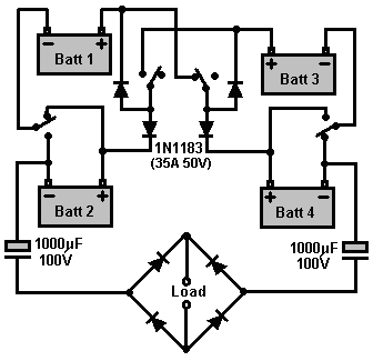 This simple-looking circuit needs to have an inductive load, preferably a motor, but that aside, consider the results of that very extended period of testing. If the switching rate and switching quality were of a sufficiently high standard, then the load could be powered indefinitely. The batteries used were ordinary lead-acid batteries, and after the three years of tests, the batteries appeared to be in perfect condition. Their tests revealed a number of very interesting things. If the circuit was switched off and the batteries discharged to a low level, then when the circuit was switched on again, the batteries returned to full charge in under one minute. As no electrical charging circuit was connected to the system, the energy which charged those batteries had to be flowing into the batteries (and load) from outside the circuit. The similarity with the Bedini pulsed battery charger circuits immediately springs to mind, especially as no heating occurred in the batteries in spite of the massive charging rate. If the circuit was switched off and heavy current drawn from the batteries, then heat would be produced which is quite normal for battery discharging. The system operated lights, heaters, television sets, small motors and a 30-horsepower electric motor. If left undisturbed, with the circuit running, then each battery would charge up to nearly 36 volts with no apparent ill effects. Control circuitry was developed to prevent this over-charging. Here we have spectacular battery charging and performance, quite outside the normal range associated with these ordinary lead-acid batteries. Are they being fed very short, very sharp pulses, like the previous two systems? It would look as if they were not, but one other very interesting piece of information co ming from Electrodyne is that the circuit would not operate correctly if the switching rate was less than 100 Hz (that is 100 switchings in one second). The Electrodyne switching was done mechanically via three discs mounted on the shaft of a small motor. It is distinctly possible that the brushes pressing on those rotating discs experienced the equivalent of “switch bounce” which plagues mechanical switches used with electronic circuits. Instead of a single, clean change over from Off to On states, there is a series of very short makes and breaks of the circuit. If this happened with the Electrodyne mechanical switching, then the circuit would have experienced very short, sharp electrical pulses at the instant of switching. The fact that the switching speed had to reach one hundred per second before the effect started happening is certainly interesting, though not proof by any means. One other detail reported by the Electrodyne testers, is that if the switching speed exceeded 800 times per second, that it was “dangerous” but unfortunately, they didn’t say why or how it was dangerous. It clearly was not a major problem with the batteries as they were reported to be in good shape after three years of testing, so definitely no exploding batteries there. It could well be as simple a thing that the voltage on each battery rose so high that it exceeded the voltage specifications of the circuit components, or the loads being powered, which is a distinct possibility. In my opinion, considering the way that the batteries responded, it would be perfectly reasonable to take it that short pulses were being generated by their mechanical system. If that is the case, then here is another system drawing fee-energy from the environment via sharp voltage pulses. The Tesla Switch circuit has some very interesting features. Pupils in school are taught that if a bulb is connected across a battery, a current flows from the battery, through the bulb and back to the battery. This current causes the bulb to light, and after a time, the battery runs down and is no longer able to light the bulb. This is completely correct. However, this teaching gives the wrong impression. It implies that the “work” done in lighting the bulb, uses up the electricity coming from the battery and that the battery somehow has a store of electricity, something like the sand in an hourglass or egg-timer, which when it runs out will no longer be able to light the bulb. In passing, it can be remarked that not a single electron which flows at a power station actually comes out of your mains wall socket. The reality is that the power station electrons flow in one winding of your local step-down transformer and cause a fluctuating magnetic field there which causes some of the many free electrons in your locality to flow into another winding of the transformer and then on to your wall socket. If you were to cause those same magnetic fluctuations yourself, then you would receive the same level of electrical power without the power company being involved. Interestingly, those same teachers will show the correct picture of the circuit, drawing it like this: 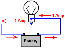 You will notice that the 1-amp current flowing out of the bulb is exactly the same as the 1-amp current flowing into the bulb. Exactly the same amount of current comes out of the bulb as the current which flows into the bulb. So, how much current is “used up” in doing the work of lighting the bulb? Answer: "None" !! Energy is never destroyed, the most that can happen to it is that it gets converted from one form to another. So why does the battery end up not being able to light the bulb any more? Well, that is a feature of the way that batteries operate. If the current flow is in one direction, then the battery gets charged up, and if it is in the other direction, then the battery gets discharged: 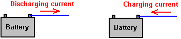 The battery getting run down, has nothing to do with the current flowing through the bulb, the battery would get run down if the bulb were left out of the circuit. The useful “work” of creating light by having the current flow through the bulb, does not “use up” any current, and more importantly, it does not “use up” any energy. Energy cannot be “used up” - it just gets transformed from one form to another. This is difficult to understand as we have been taught that we have to keep buying energy from the electricity supply companies to power our equipment. The false idea is that we buy the energy, and it then gets “used up” in the equipment, so we have to buy some more to keep the equipment going. We accept it because that’s what we were taught. It isn’t true. The current flowing through the bulb can be arranged to be a charging current for another battery. It can both light the bulb and charge another battery without needing any extra current:  Here, the circuit is powered by battery 1 as before, but this time the current goes on to charge battery 2. Yes, battery 1 gets discharged just as before, but the plus side is that battery 2 is getting charged up all the time. The final step is to swap the batteries over: 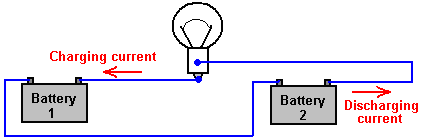 And now, the newly charged battery 2 lights the bulb and charges up battery 1 again. Seem impossible? Well it isn’t. Nikola Tesla demonstrates this with his “4-battery switch” system where he chooses to use four identical batteries to implement this circuit: 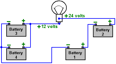 With 12-volt batteries as shown here, the bulb has the same 12 volts across it as it would have had with the single battery shown in the first diagram, as batteries 1 and 2 are wired “in series” to give 24 volts, while batteries 3 and 4 are wired “in parallel” to give 12 volts. The Tesla switch circuit swaps the batteries over with 1 and 2 taking the place of 3 and 4, hundreds of times per second. If you wire a simple manual change-over switch and use it to change the battery arrangement as shown above, tests show that the batteries can power the light for a longer time than if they were not switched over. The snag is that batteries are not 100% efficient and so you can only take about half of the charging current back out of the battery again. For a Tesla 4-battery switch to operate indefinitely, there has to be inflow of outside energy to offset the poor efficiency of a lead-acid battery. NiCad batteries are more efficient and so they are sometimes used in this circuit, where they can work well. There is another important factor involved in battery-charging circuits to be used with normal lead-acid batteries and that is the characteristics of the materials involved. The charging process in this switching circuit is carried out by electrons flowing down the connecting wire and into the battery. The electrons flowing along the outer surface of the wire, move very rapidly indeed. The main current inside the battery is carried by the charged ions inside the lead plates inside the battery. These ions are hundreds of thousands of times heavier than the electrons. This doesn’t matter at all once the ions get moving, but in the initial split second before the ions get going, the incoming electrons pile up like in a traffic jam tail-back. This pile-up of electrons pushes up the voltage on the terminal of the battery, well above the nominal battery voltage, and so the charging starts off with a high-voltage, high-current pulse into the battery. This is not normally noticed when using a standard mains-powered battery charger, as switch-on only occurs once during the whole charging process. In the Tesla switch shown here, and in the Bedini circuits shown earlier, this is not the case. The circuit takes advantage of this difference in momentum between the electrons and the lead ions, and uses it repeatedly to great advantage. The technique is to use very short duration pulses all the time. If the pulses are short enough, the voltage and current drive into the receiving battery is far greater than a quick glance at the circuit would suggest. This is not magic, just common-sense characteristics of the materials being used in this circuit. A person unfamiliar with these systems, seeing John Bedini’s many advanced circuits for the first time, might get the impression that they are just crude, roughly-built circuits. Nothing could be further from the truth. John often uses mechanical switching because it gives very sharp switch-on and switch-off times. John is a complete master of this circuitry and knows exactly what he is doing The Electrodyne Corporation tested the Tesla 4-battery circuit over a period of three years. They found that at the end of that period, the batteries did not show any unusual deterioration. The batteries used were ordinary lead-acid batteries. The system operated lights, heaters, television sets, small motors and a 30-horsepower electric motor. If the batteries were run down to a low level and then the circuit switch on with a load, the recharging of the batteries took place in under one minute. No heating was experienced during this rapid charging. Heat was only produced during discharge cycles. If left undisturbed, each battery would charge up to nearly 36 volts. Control circuitry was developed to prevent this over-charging. They used mechanical switching and stated that below 100 Hz there was not much advantage with the circuit and above 800 Hz it could be dangerous. They didn’t mention why they consider that higher rates of switching could be dangerous. If we consider what exactly is happening, perhaps we can work out why they said that. The charging situation is like this: 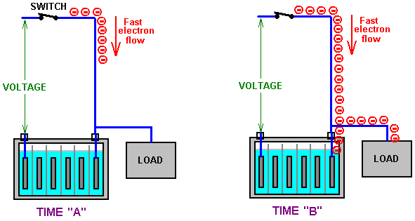 At Time “A” the switch closes, connecting a voltage source (battery, charged capacitor, or whatever) to a lead-acid battery. Electrons start flowing down the outside of the connecting wire. Being very light and having little obstruction, they move very fast indeed (the electrons inside the wire only move a few inches per hour as getting through the wire is difficult). All goes well until Time “B” when the leading electrons reach the lead plates inside the battery. Here, they have a problem, because the current flow through the plates is carried by lead ions. Lead ions are very good at carrying current, but it takes them a split second to get going due to their inertia. That split second is critical and it opens the door to free-energy. In that split second, the electrons pile up because they are still arriving down the wire at very high speed. So, at Time “C” they have built up into a large body of electrons. 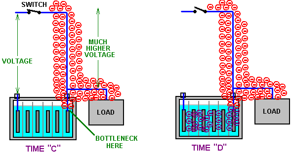 This large body of electrons has the same effect as if there had been a sudden connection to a much higher voltage source capable of supplying a much higher current. This situation only lasts for a very short time, but it has three very important effects. Firstly, at Time “D”, it drives a much larger current into the battery than could reasonably expected from the original voltage source. Secondly, this high voltage pulse alters the Zero-Point Energy field (the space-time continuum) in which the circuit is located, causing extra energy to flow into the circuit from the outside environment. This is a bit like sunshine generating current flow in an electric solar panel, but instead of visible sunshine, the energy flow is not visible to us and we have no instruments which react to this excess energy. Thirdly, the excess energy flows into the battery, charging it much more than would be expected, and at the same time, some of the excess energy flows into the load, powering it as well, and further, some of the flow goes back into the driving circuit, lowering its current draw. Remember Dave Lawton’s Water Fuel Cell? Well Dave also connects a bulb across the cell to extract additional energy: 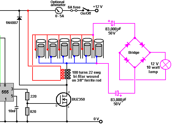 A really interesting feature of this extra power draw-off is that when Dave adjusts the frequency to the optimum value, the supply voltage remains unchanged but the input current drops noticeably and the brightness of the lamp increases markedly. Less input power at the same time as greater output power - the circuit hasn’t changed, so where is the extra power coming from? One possibility is certainly that it is flowing in from the environment. So, returning to our excess energy is collected from the environment and used to both charge the battery and at the same time, perform useful work. The old saying “you can’t have your cake and eat it” just does not hold in this situation as that is exactly what happens. Instead of the battery being run down from powering the load, the load gets powered and the battery gets charged up at the same time. This is why, with this system, a discharged battery can be used to apparently run a motor. It works because the plates in the discharged battery are made of lead which forms a bottleneck for the electron flow, causing the environment to charge the battery and run the load at the same time. That is why you get what looks like the magical effect of a discharged battery appearing to power a load. In passing, the more discharged the battery, the faster it charges as the environment adjusts automatically to the situation and feeds greater power into a flat battery. The environment has unlimited power available for use. John Bedini who is expert in this field has had motors running continuously for three or more years with the battery never running down and the motor doing useful work all the time. Great battery? No, - great environment !! Not necessarily exactly the same effect, but Joseph Newman’s motor exhibits this same result, much to the discomfort of a conventionally taught scientist, who measured the motor at a minimum of 400% “efficiency” (really COP = 4) and probably nearer 800% when all the major factors were taken into account. One thing which really bothered him was that when powering the motor on almost completely discharged dry cell batteries, the voltage measured at the motor was some three times the voltage at the batteries. That is very upsetting for a scientist who is not aware of the zero-point energy field and considers most systems to be “closed” systems, when in fact, there are practically no “closed” systems in our universe. Surprise, surprise, the Newman motor operates on electrical pulses. Anyway, returning to the Tesla 4-battery switch. For the vital build up of excess electrons to take place, the switch closure has to be very sudden and very effective. A thyristor or SCR might be suitable for this, but the sharp switching of a PCP116 opto-isolator driving an IRF540 FET is impressive and a TC4420 FET-driver could substitute for the opto-isolator if preferred. It is likely that the Tesla 4-battery switch circuit switching in the 100 Hz to 800 Hz region operates in this way. This drawing in of excess energy from the environment can be further enhanced by suddenly cutting off the electron flow from the original voltage source while the excess electron pile-up is still in place. This causes a sudden (very brief) further surge in the excess power, building up the voltage and current even further and increasing the battery charging and load-powering drive. An even greater effect can be had if the next, short, sharp pulse is applied to the battery/load combination, just before the effect from the last pulse dies away. It may be that this is the situation which the Electrodyne Corporation people encountered when the pulse rate went over the 800 Hz rate. It may not be so much a case that the battery and load could not take the power, but more a case that the components which they were using were not rated high enough to carry that level of power. They do mention that if they went further, that they found that some of their circuit components started failing through not having high enough ratings (notice that the output capacitors are rated at 100 volts which is eight times the nominal battery voltage). This was hardly a problem, considering that they had 12-volt batteries operating happily at 36-volts if they wanted that. They ended up building circuitry to hold the voltages down to a convenient level. To summarise the situation. The Tesla 4-battery switch appears to do the impossible through: 1. Catching the current coming out of the load and using it to charge another battery instead of wasting it. 2. Providing very short, sharp, and rapid switching pulses which exploit the momentum of the lead-ions current flow. 3. Pulling extra energy in from the local environment to both charge the batteries and power the load at the same time This leaves aside the possibility of two further gains available through very precise timing of the switching pulses (mainly to make the power available more easily and cheaply handled). So, it should be borne in mind that the practical issues involved in getting this circuit operating effectively are primarily about very fast, clean and well-timed switching. Stranded, very large diameter, high-current rated wire will be helpful in getting the draw of excess energy into the circuit. Here is the switching sequence for the Tesla 4-battery switch system: 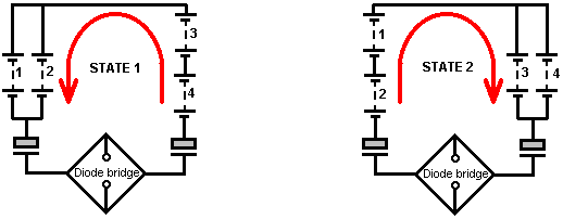 As you can see, this is essentially the same circuit with batteries 1 and 2 swapping over with batteries 3 and 4. But he has added in two capacitors and a diode bridge of four diodes to power the “load” which needs to be inductive for this circuit (transformer, motor, etc.). The circuit used by the Electrodyne Corp. testers was: 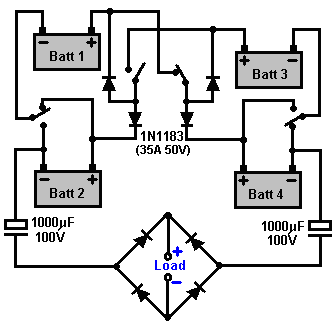 This circuit was reported to have excellent results using six On/Off switches on a motor-driven cam arrangement: 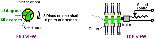 Here three discs are mounted on the shaft of a motor as shown here. These are insulated from each other and the conducting sectors are aligned, and so are the brushes. The arrangement gives a mechanical switching such that when the upper brushes are short-circuited together, the lower brushes are open-circuit. As there is a requirement for an inductive load for this circuit, the motor of a mechanical switching system could well form part of the load. Many people prefer solid-state switching to mechanical switching and so set out to design suitable circuits. It needs to be borne in mind that a very precise 50% Mark/Space ratio is essential and that may not be so easy to arrange. The common idea of using mechanical relays is not very practical. Firstly, relays have trouble switching at the speeds suggested for this circuit. Secondly, with a contact life of say, two million and a switching speed of just 100 times per second, the relays would reach their projected lifespan after two weeks of operation, which is not a very practical option. To get an exact 50% Mark/Space ratio, possibly the following style of circuit could be used with a multi-turn preset resistor in position “A”: 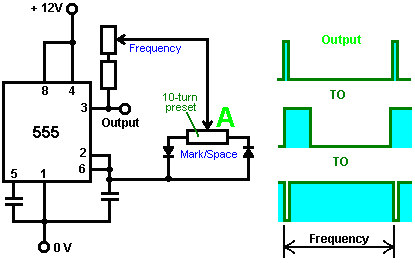 Here, the frequency is not noticeably affected by adjustment through a very wide range of Mark/Space settings. The output from Pin 3 needs to drive a very sharp switching combination such as a TC4420 FET driver connected to IRF540 FETs. As the circuit diagram used by the Electrodyne Corp. people is a little difficult to follow, perhaps the following diagrams may help by showing the current flow during the two states: 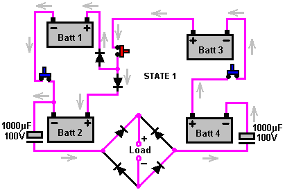 Here, batteries 1 and 2 are wired across each other while batteries 3 and 4 are wired in series (in a daisy-chain). This needs three On/Off switches and the two diodes are inserted so that the plus terminal of battery 1 is not permanently connected to the plus terminal of battery 2, because in State 2, that connection must not be made. 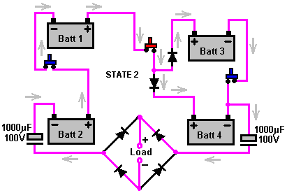 The State 2 wiring is almost identical, requiring another three On/Off switches and two diodes to avoid a permanent link between the plus terminals of batteries 3 and 4. Here is a suggestion for doing that with PCP116 fast-operating opto-isolators: 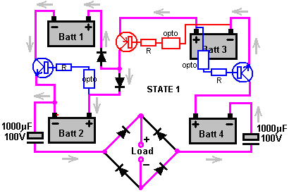 Each of the three mechanical switches are replaced with a transistor - one PNP type and two NPN type. These need to be able to handle 30 amps, so although not shown here, they will probably be Darlington pairs with the low gain of the high-power transistor being boosted by the additional gain of a driver transistor, perhaps something like a 2N3055 / 2N2222A combination. The transistor base current comes via a limiting resistor fed from an appropriate battery terminal a fixed 12 volts above it. The switching is controlled via an opto-isolator and the three opto isolators which switch together (shown above) are driven from one side of an astable multivibrator. The other three opto-isolators needed to perform the switching for State 2, will be Off during State 1, so they will be driven by the inverted version of the same oscillator waveform. This ensures that three will be On and three will be Off at the same time. 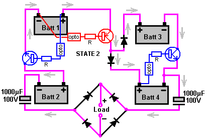 The suggested transistor switching for the State 2 situation is shown above. This is just an attempt to perform the switching with the most simple components available, and has been shown to work in practice. The mechanical changeover switch can be replaced with transistors: 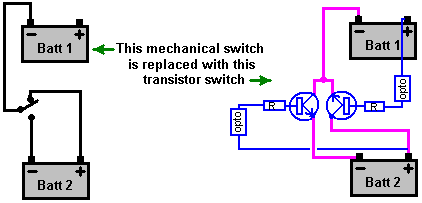 and 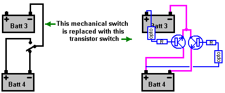 The Electrodyne Corp. experience indicates that it is likely that additional circuitry will be needed to cut off the extra power when the energy in the batteries rises to the point where it could endanger the equipment which it is powering or the components in the circuitry. The electronics tutorial which forms part of this eBook shows the principles which can be used for the design and construction of this kind of circuitry. It might be sensible to have the control circuitry kick in at fourteen or fifteen volts and drop out again when the battery voltage drops back to 12.5 volts or so. This switching circuit is said to be able to power its load indefinitely. It is also said that if one of the batteries is fully discharged, or nearly fully discharged, then putting it in any of the four positions returns it to full charge within one minute. The connecting wires should be at least 30 Amp current carrying capacity and the individual diodes and the diode bridge are rated at 35 Amps 50 Volts. The circuit is intended for use with lead/acid batteries but it has been used successfully with rechargeable NiCad batteries. The circuit provides about 12 volts as the output, so mains equipment would be operated using a standard, commercial “inverter” which converts this low DC voltage to normal mains AC voltage capable of powering TV sets, DVD recorders, or whatever. There have been various different versions of the Tesla 4-battery switch circuit. Some of these show additional diodes, making an absolutely symmetrical circuit where the current flow can continue even if the load is disconnected, as shown here: 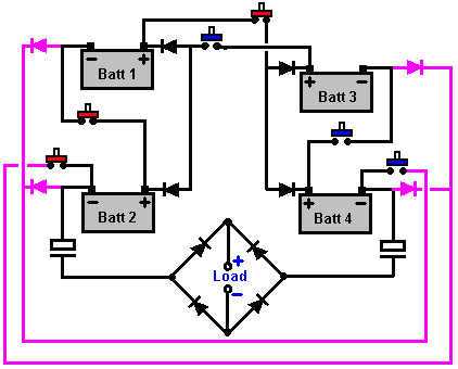 I have been asked to explain how the switching might be achieved. Usually there are many different way to achieve any wanted effect and switching circuits are no exception. What follows then is just a suggestion for one possible way of doing the switching and must not be thought of as the way in which the switching must be done. The main objectives for the switching circuit are to have very fast switching and to have an exactly equal "On" period for the two switched states. As electronic components have manufacturing tolerances, it is not possible to have components with exactly the same values unless they are selected from a large stock of the same component. To deal with this situation, and avoid spending large amounts by buying high-specification components, we will aim for a manually adjusted circuit, where the switch "On" time can be adjusted to give exactly the right value: 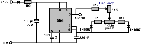 This circuit allows the Mark-Space ratio to be adjusted without altering the frequency, and the frequency can be adjusted without affecting the Mark-Space setting in any way. In the Tesla Switch circuit, three switches need to be in their On position and the other three switches in their Off position, so we will arrange this by using the ordinary NE555 timer circuit shown above, with it's adjustable Mark-Space ratio (that is, variable On-to-Off ratio). We will use this circuit to drive six opto-isolators which will turn the six transistors On and Off in groups of three as required. To get the very high switching speed needed, PCP116 opto isolators should be used and although these are difficult to find, every effort should be made to get them as they enhance the switching speed. One feature of the Tesla Switch is the fact that it should have an inductive load. In simple terms, that means that the load should be a motor or a transformer. The need for an inductive load may well be the back-EMF voltages which are developed when the current flowing through the load is cut off suddenly. So, let's start with the circuit shown below which has a transformer as the load. In this circuit, switches 1, 2 and 3 switch On and Off at the same time, and switches 4, 5 and 6 form the second group. If one group of three switches is On, then the second group of switches needs to be Off. 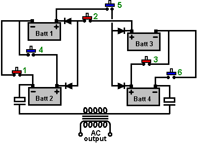 The following details show the preliminary stages of an implementation using 4N25 opto-isolators which are not nearly as satisfactory as PCP116 chips which switch typically 30 times faster. However, the circuit adaption is very minor in that it is only one board which needs to be altered. The circuitry choice was as follows: 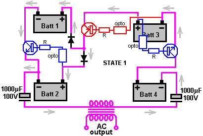 Here, each of the three mechanical switches are replaced with a transistor - two NPN type and one PNP type. As these were required to be able to handle 30 amps, the initial build used the Darlington pair devices MJ11016 for the NPNs and MJ11015 for the PNPs as these are rated at 30 amps and have a minimum gain of 1,000, allowing quite low switching currents for the control circuitry. The switching is controlled via an opto-isolator and the three opto isolators which switch together as shown in the diagram above, are driven by the output of a 555 timer chip astable multivibrator (Chapter 12 explains all of this, so if you are not familiar with these things, then perhaps it would be a good idea to read through that chapter now). The other three opto-isolators needed to perform the switching for State 2, will be Off during State 1, so they will be driven by the inverted version of the same 555 signal. This ensures that three will be On and three will be Off at any time. 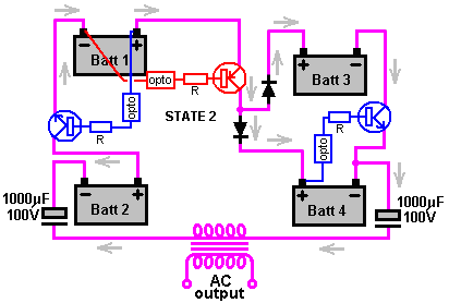 We need to get an inverted output from the timer circuit, that is, an output which goes high when the 555 timer chip goes low and which goes low when the 555 timer chip output goes high. There are various ways to do this, but the way shown here is the very simple method of using a transistor. If we were using mechanical switching, we would choose to use a switch which opens one set of contacts before closing the other set. We can arrange that by making the switch-on of the inverting transistor adjustable, like this: 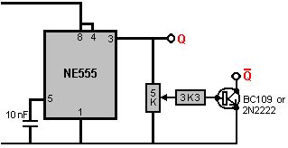 The 5K variable or preset resistor is placed across the output of the NE555 timer chip. This resistor will have either a very low voltage across it or a voltage nearly the same as the battery supply. Please remember that the 555 chip can't handle supply voltages over 15 volts and will burn out if you feed them anything more than that. The Tesla Switch circuit with 12 volts batteries should be ok as you don't want the batteries to exceed 14 volts anyway. When the 5K variable resistor has a high voltage on it, every voltage from zero to that high voltage can be selected by moving the slider of the resistor along its track. At some point when the slider is gradually moved up from the minimum voltage point, the transistor will turn on. The 3.3K resistor limits the current if the slider is moved to the very highest voltage point. The output transistor can be a BC109 or a 2N2222 type as these are high-gain types easily capable of handling the tiny current needed to drive three opto-isolators. The variable resistors come in a wide range of types. It is probably best to use a preset type as they are very easy to adjust and hold their settings very solidly. Also, when the correct setting is found, the component will be left on that position permanently. Some common types are: 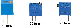 where some can be adjusted from the top and others adjusted from the side. All of tghem can be mounted directly on the strip-board or printed circuit board used to construct the circuit. The initial build can be done in simple stages. This is to ensure that the switch wiring is correct before the semiconductor switching is attempted. Although the circuit does not show it, it would be no harm to have a fuse on each battery as a battery holds a considerable store of electrical energy and is easily capable of starting a fire if there is an inadvertent short-circuit. The excessive current draw caused by a short-circuit is not visible, and the first you know of it with a battery-powered circuit is the burning smell and wisp of smoke. Even using a mains-powered power supply unit with voltage and current displays, it is still very easy indeed to miss a short-circuit as you tend not to be watching the current display when the problem occurs. To make the assembly and subsequent adjustment simple, a standard strip of ordinary screw-connectors is used. For initial testing, a four-pole three-way wafer switch is used. The switch provides the two changeover switches and the single On switch and the single Off switch. It also has the advantage that the third switch position switches the entire circuit off. The initial test, uses a low-current load of two LEDs with limiting resistors wired in opposite directions. This shows the direction of current flow and confirms that the switching is working correctly. By omitting the capacitors and pulse switching, it allows leisurely checking of the wiring and operation: 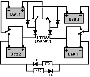 The physical layout with a mechanical rotary 4-pole 2-way switch could be: 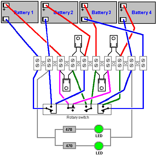 And the diodes used here happen to be high-speed, IXYS type DSEI 12-10A which were to hand and which are rated at 1,000 volts, 12 amps. While this does limit the initial current capacity, there is no reason why these cannot be doubled up or tripled up to allow a higher current. The batteries used initially in the test are very small 1.2 AHr types and so the allowable current draw from them is quite limited. If this circuit does not operate correctly straight off, it is quite likely that the diodes are the wrong way round. In this physical layout, the back of the diodes all face upwards. This particular build looks like this: 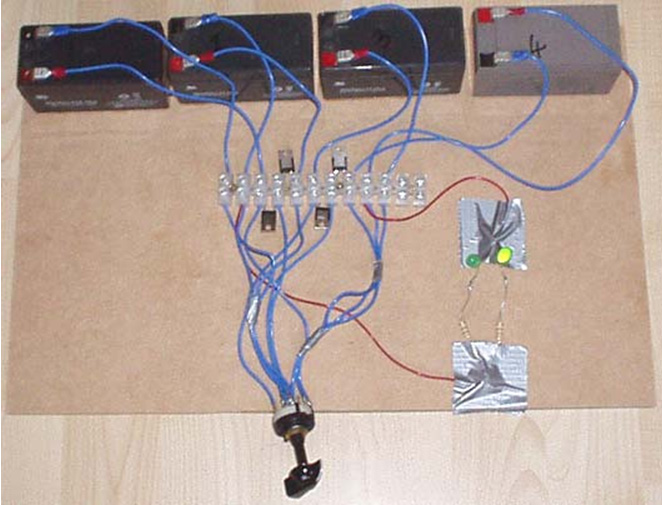 State 1 with the right-hand LED lit. 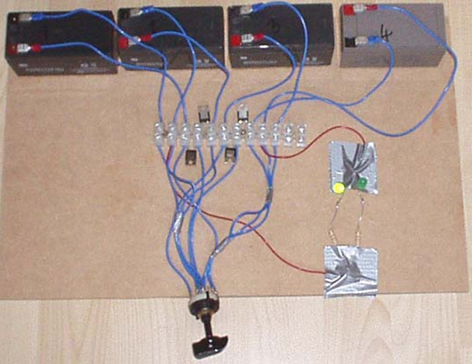
State 2 with the left hand LED lit. 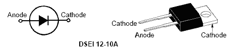 So far, this shows that the batteries, diodes and switch connections are correct. The next step is to change the switching for one of the states to transistor switching. This requires three transistors, three opto-isolators and three resistors. The transistors are housed in the large TO-3 package and so will mount on the base board. The small components can be mounted on a standard small piece of stripboard, 10 strips with 38 holes per strip: 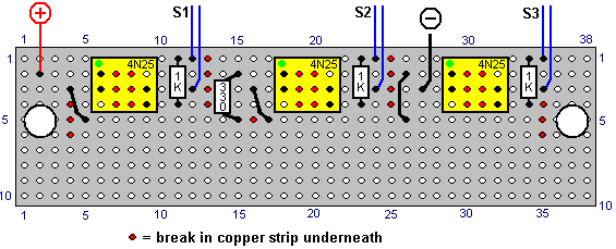 There should be a voltage drop of at least 10 volts (11.5 volts to 1.5 volts) across the resistor feeding the base of the transistors. If the transistor current is 10 amps and the gain 1,000, then 10 milliamps will be needed as the current into the base, so with a 10 volt drop the resistor should have a value of 1K. The current through the LED section of the opto-isolators is limited by a 330 ohm resistor, which can be positioned anywhere convenient in the chain as the same current passes through all of the LEDs inside the opto-isolators. The circuit diagram for each set of three opto-isolators could be: 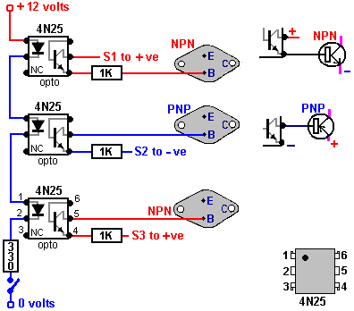 The first part of the circuit is now wired up to switch when the first chain of three opto-isolators is powered up to feed base current to the three power transistors. When this section is working correctly, then the board containing the first chain of three opto-isolators is extended to hold an identical additional chain of three opto-isolators as shown here: 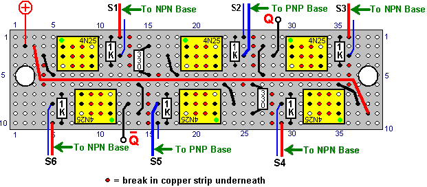 You will notice that for convenience, the physical layout is arranged so that the strip-board is just rotated through 180 degrees and the wiring diagram for the first three optos is used again for the second three. 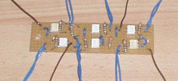 The underside of the board looks like this when turned over from left to right: 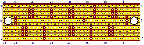 And with the power transistors wired in place and ready to receive the opto-isolator connections: 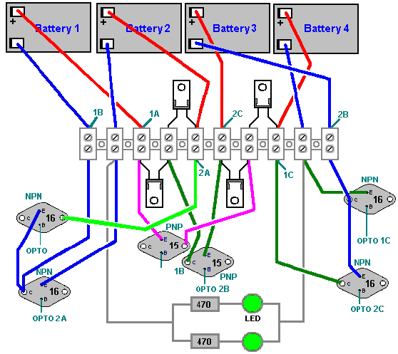 The two chains of opto-isolators now do the actual switching when they are powered up in turn. This spread-out simple layout makes testing and checking easy and no heat sinks are needed for low-current testing: 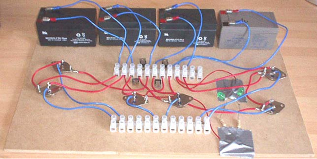 So with the opto-isolators wired in place, the switching is solid-state: 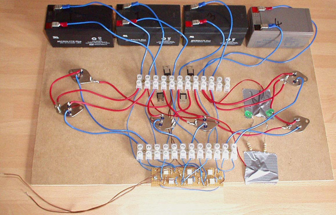 Here, when one of the brown wires, seen at the bottom left hand side of the picture, are touched to the minus terminal of battery 2, one LED lights up. Disconnecting the wire and touching with the minus terminal of battery 2 with the other wire, lights the other LED. Obviously, you don’t connect both of the wires at the same time. It would be sensible to have a fuse on the positive lead coming from each of the batteries as this protects against accidental short-circuits and against the failure of any of the main power semiconductors. In the picture above, most of the wires coming from the opto board appear to be connected via the lower terminal block. This is not the case as only the six leads coming from the base connections of the power transistors actually use the terminal block, while the other wires are just routed through the block as being the most direct way of reaching their connection points further in on the board. It should be stressed that the opto-isolator connections are not random. These are not mechanical switches where it doesn’t matter which way round the switch is connected. The optos are transistor junctions and the connections to the PNP transistors in the middle of the board are made the opposite way round to that for the NPN transistors. In other words, Pin 5 goes to the base of a PNP transistor so that it gets switched through to the negative side of the battery powering it, while Pin 4 goes to the base of an NPN as it needs to be connected to the positive side of the battery powering it: 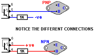 As well as paying attention to which wires go to the bases of the six transistors, it should be noted that if you wish, instead of having two wires running from the board to the positive supply for the board, that an alternative is to make the positive line connection for the second chain of opto-isolators physically on the board, as both chains are fed from the same voltage source, which for the moment, is battery 2. When this stage is working correctly, the manual powering of the opto chains is replaced with a solid-state switching board to allow high-speed, reliable switching. There are various options for the design of this switching circuit. The initial design opts for simplicity and hopes that the opto-isolator switch-on and switch-off rates will be fast enough to make the overall circuit operate as desired, pulling excess energy from the local environment in spite of using 4N25 opto-isolators. This may look a little strange with the collector of the output transistor not appearing to be connected to anything, but it connects to one of the chains of three opto-isolators with its built-in current-limiting series resistor. The normal Pin 3 output from the NE555 chip, connects directly to the other opto-isolator chain, so one will be switched off and the other one switched on at the same time. The timing resistor can be varied from 3.3K to 50.3K ohms and that combines with the 220nF capacitor to give switching in the required frequency range. 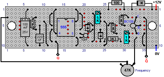 And the underside of the board when turned over from left to right, is: 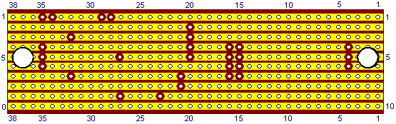 Tuning of the Mark-Space preset resistor is initially set to its centre position and if the batteries start to develop different voltages, then it is adjusted slightly and running continued, aiming for exactly the same voltage on each battery. The batteries should be the same age and the same AHr capacity. Recently, a patent application has been lodged on what is effectively the Ron Cole one-battery switch and the Tesla Switch. I must admit to being highly doubtful about the notion of using capacitors as an energy source (unless the switching frequency is so high that the capacitors have insufficient time for their voltage to drop significantly), I am including the re-worded patent here. Some experimenters have reported overall battery energy gains with switching speeds of 0.5 Hz or less, which means that in circuits of that type, mechanical switching should give a reasonable switch contact life. This patent has needed a fair degree of attention as the person writing it does not have a full grasp of English and confused the word "load" with the word "charge". Let me say again, that the following patent application is included here primarily for interest sake, rather than being the definitive way of making a circuit of this type.
ABSTRACT In the invention an electric current circulates from the battery UB, through the electric motor M, and the diode D1 charges the capacitors CA and CB, connected in parallel, which, once charged, are connected in series, giving rise to a difference in voltage in relation to the battery, causing half the charge of the capacitors to be returned to the battery through the diode D2, whilst with a new parallel connection, the capacitors recharge, this charge being equal to that which had been previously transferred from the capacitors to the battery, so that by means of the cyclic connection of the capacitors in parallel and series the energy is transferred from the battery to the capacitors and from the capacitors to the battery, thus considerably extending the range of the battery and operation of the motor. OBJECT OF THE INVENTION This invention relates to a method and device enabling the electrical energy with which a charge is supplied to be recovered using a self-rechargeable electricity source in which, which by means of a circuit, the current circulating from an accumulator or battery through a load, e.g. a motor, is fully returned to the same, thereby considerably extending its range. More specifically, two capacitors that are connected cyclically from parallel to serial and vice versa are charged through a motor during the connections in parallel, whilst in series connection, when its voltage doubles, they return the electricity, recharging the battery. This source represents a closed system which does not require an energy supply from the outside, except to compensate for the losses produced, the range of the battery being limited by the number of charges and discharges that the same technically permits. BACKGROUND TO THE INVENTION A load, such as an electric motor, is connected to a battery or accumulator with a certain charge, which will be progressively discharged by it, this discharge being directly proportional to the connection time and to the current circulating through the motor. It is therefore necessary to supply fresh energy from an external source to recharge it. Systems that enable the energy consumed by the load to be reused are not known in the state of the art. DESCRIPTION OF THE INVENTION A first aspect of the invention relates to a method for supplying a load with recovery of electrical energy, which comprises supplying a load with electrical energy deriving from the first electrical energy accumulator, and returning at least a proportion of that electrical energy after it passes through the load to the first accumulator for the purpose of recovering the energy supplied. The electrical energy, after passing through the load, is recovered by second electrical energy accumulator, from where it is transferred to the first accumulator, giving rise to cyclic transfer of electrical energy between the first and second energy accumulators. The recovery of energy from the second accumulator and transfer to the first accumulator may be achieved without passing the energy through the load. In another alternative implementation, the energy is recovered from the second accumulator and passed to the first accumulator through the load, in which case the polarity of the load is reversed during the recovery of energy through the load. The transfer of energy is brought about by cyclically connecting two or more electrical energy accumulators between parallel and serial connections. A second aspect of the invention relates to a device for supplying a load with recovery of electrical energy, which comprises a first electrical energy accumulator and a second electrical energy accumulator, where the load is connected between the first and second accumulators. The device may be provided in one embodiment with a unidirectional connection device, for example, a diode which is connected in parallel to the load, causing circulation of the electrical energy recovered after passing through the load, and via which the electrical energy is returned to the first accumulator. The first electrical energy accumulator may be a battery. The second electrical energy accumulator might be two or more capacitors with switching to cyclically connect them between parallel and serial connection configurations. The invention constitutes a self-rechargeable source of electrical energy which enables the range of a battery to be considerably extended so that the current circulating from the same through a motor charges two capacitors connected in parallel, up to the voltage level of the battery, by means of contacts. These capacitors, once charged, are connected in series, producing double their voltage, and they then return the energy to the battery, thereby extending its range. Once the losses have been compensated for, the duration of the extended range depends on the charging and discharging properties of the capacitors. The existence of the difference in voltage between the battery and the capacitors connected both in parallel and in series, and which give rise to the displacement of energy from the battery to the capacitors and vice versa, is used to supply the motor connected between the battery and the capacitors, comprising the self-rechargeable source of electrical energy. When connected in parallel, the capacitors are charged through a motor and a diode, and when connected in series, they are charged through another diode, the voltage of the motor being half that of the battery. On the other hand, if the motor is connected between the battery and the serially-connected capacitors, the latter, which are charged in parallel through a diode and are discharged by means of the motor and the other diode, will supply the motor with a voltage equal to that of the battery, whilst a capacitor connected in series to the winding of the motor guarantees its operation without loss of power. Instead of the two capacitors, two batteries connected in series and another two connected in parallel may be used, between which batteries a motor is connected, the current circulating in this case from the batteries connected in series through the motor to the batteries connected in parallel. The serially-connected batteries are then connected in parallel, by means of switching contacts, and the other two parallel-connected batteries are then connected in series, reversing the direction of the current, whilst the connections of the motor are inverted by means of the simultaneous switching of other contacts in order to maintain the polarity and direction of rotation of the motor. In one possible embodiment of the invention, another two capacitors and a transformer with two primary windings, or a motor with two windings are added to the device previously described, each pair of capacitors cyclically switching from parallel to serial connection and vice versa so that during the parallel connection cycles, two of the capacitors are charged through one of the windings up to the voltage level of the battery at the same time that the other two capacitors are connected in series, double their voltage and are discharged by means of a second winding to the battery. The reduced level of energy losses brought about mainly by the dissipation of heat and in the capacitors, as well as by the charge factor of the batteries, is compensated for from an external source, and because the sum of the current circulating through a winding of the motor or transformer charging two of the capacitors and the current simultaneously circulating from the other two capacitors through the second winding, recharging the battery, plus the current which is supplied from the external source, is equal to zero, because of the work carried out by the motor or the loads which are connected to the alternating voltage induced in the secondary of the transformer, no discharge of the battery takes place. DESCRIPTION OF THE DRAWINGS In order to supplement the description now being given, and with the aim of contributing to a better understanding of the characteristics of the invention, according to a preferred practical embodiment, a set of drawings is attached as an integral part of this description, in which, for informative and non-restrictive purposes, the following is shown: 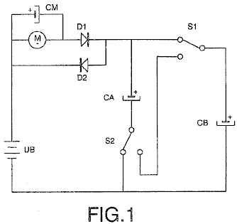 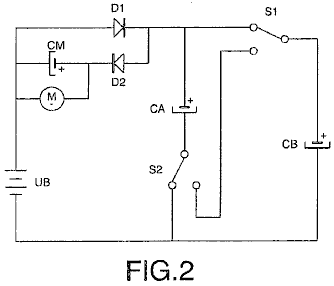 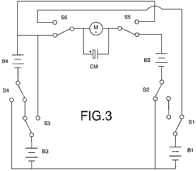 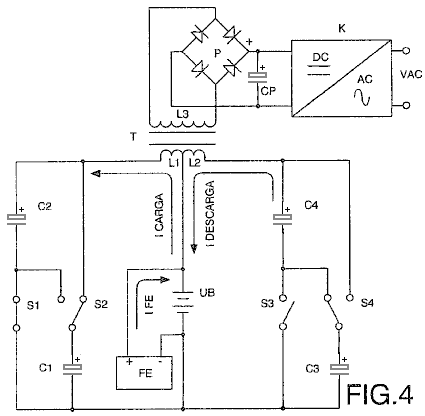 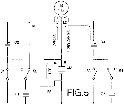 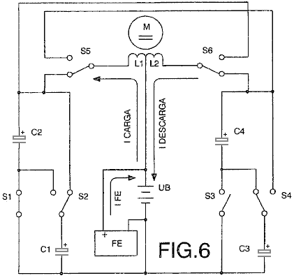 PREFERRED EMBODIMENT OF THE INVENTION In a preferred embodiment shown in Fig.1, the load consists of a direct current motor M, the battery UB, and the second accumulator which consists of a pair of capacitors CA and CB. The capacitors CA and CB are connected to each other in parallel by means of two switches S1 and S2. These capacitors are charged through the motor M and diode D1 to a voltage level equal to that of the battery UB, the charge being Q = (CA+CB)UB, and while these capacitors are being charged, the motor M is rotating. 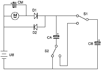 When both capacitors are fully charged, they are connected in series by the switch contacts S1 and S2. This produces a voltage which is twice the value of the voltage of the battery UB, resulting in the charge which is given by Q = 2 x UB x (CA+CB) / 2 which is Q = (CA+CB)UB, which shows that once charged, the charge Q of both capacitors is identical both in parallel and in series. Diodes D1 and D2 ensure that current flow through the motor M is only ever in one direction. Immediately after capacitors CA and CB are connected in series, they return half of their charge through diode D2. Switches S1 and S2 then connect the capacitors CA and CB in parallel. In this arrangement, they start off with half of the battery voltage. They charge immediately, regaining the battery voltage through the motor M and the diode D1. By means of repeated cyclic switching of the capacitors CA and CB from parallel to serial connection mode, the current circulating from the battery UB through the motor M to the capacitors, and from these to the battery, recharging it and extending its range, constitutes a self-rechargeable source of electrical energy. 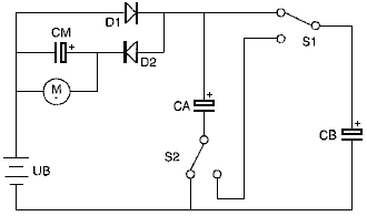 In a second practical embodiment shown in Fig.2, the motor M is connected between the battery UB and the capacitors CA and CB by means of the diode D2. The capacitors are charged directly through the diode D1 and are discharged through the motor M and the diode D2, the values of the charges on the capacitors CA and CB previously described in the example shown in Fig.1 remain unchanged, the difference in this circuit is that the voltage applied to the motor M is the full battery voltage in this case. The charging rate of the capacitors CA and CB is determined by the intensity of the current flowing through the motor M, to which is connected in parallel, the capacitor CM which guarantees that the operation of the motor is maintained at maximum power. It is possible to substitute a battery, preferably a rapid charge battery, for capacitor CM. 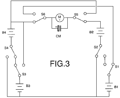 In another embodiment shown in Fig.3, the first and second accumulators consist of pairs of batteries B1, B2 and B3, B4. Therefore, in this embodiment, two pairs of batteries are used instead of the capacitors CA and CB. Batteries B and B2 are connected to the switches S1 and S2, and the pair of batteries B3 and B4 are connected to the switches S3 and S4. The switches S1 to S4, connect the pairs of batteries with which they are associated, into series or parallel configurations, depending on the position of the switches. While the batteries B1 and B2 are connected in parallel, the other two batteries B3 and B4 are connected in series, and the motor M rotates as a result of the difference in voltage between the batteries, as it is connected between both pairs of batteries. At the same time, the current circulating through the motor from the serial connected batteries recharges the two parallel-connected batteries. The switches S1 to S4, which connect the batteries B1 and B2 in series and the batteries B3 and B4 in parallel then switch, thus reversing the direction of the current flow, and at the same time, the switches S5 and S6 change positions in order to maintain the correct polarity for the motor and its direction of rotation. The two capacitors and the batteries may be switched by means of any mechanical, electromechanical, electrical, electronic or other element that meets the conditions described with the purpose of obtaining a self-rechargeable electrical energy source. These switching operations may be controlled by any known method, for example, a programmable electronic circuit. In the preferred embodiments previously described, the load consists of a direct current motor, but as an expert in the field may understand, the load may also consist of any type of resistive (?) and/or inductive load. 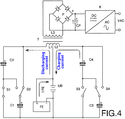 Another preferred embodiment is shown in Fig.4, where a transformer T with two primary windings L1 and L2 is connected between the battery UB and the two pairs of capacitors C1 and C2, plus C3 and C4, causing the two capacitors C1 and C2 to switch their connections from parallel to serial and back again by means of the contacts S1 and S2, and causing the capacitors C3 and C4 to switch by means of contacts S3 and S4, so that during the cycles of connection of the capacitors C1 and C2 in parallel, the latter are charged via the winding L1 up to the voltage level of the battery, whilst at the same time the capacitors C3 and C4 are connected in series and provide double their voltage, the battery being discharged by means of the winding L2, in which case the charging and discharging currents to circulate in the same direction. On the other hand, during the cycles of connection in parallel of the capacitors C3 and C4, which are charged through the winding L2 up to the battery voltage level, the capacitors C1 and C2 are connected in series to provide double their voltage and are discharged into the battery through the winding L1. The direction of the charging and discharging current therefore changes, thus inducing in the secondary winding L3 an alternating voltage whose frequency depends on the speed of switching of the contacts mentioned, and after being rectified by means of the bridge of diodes P and filtered by the capacitor CP, the resultant DC voltage is converted to a sinusoidal voltage by means of a circuit K. The connection in parallel of one pair of capacitors and the connection in series of the other pair take place at the same time. Therefore the sum of the current circulating from the battery through one of the windings, charging two of the capacitors, and the current circulating from the other two capacitors through the other winding to the battery, is approximately zero. From an external energy source FE the minimum energy losses caused essentially by dissipation of heat and in the capacitors, as well as by the charging factor of the battery, are compensated for, with the result that the sum of the current circulating from this source external to the battery and the charging and discharging currents of the capacitors is equal to zero. Therefore the battery is not discharged and its range does not depend on the work developed by the motors or the loads connected to the secondary winding L3 of the transformer T, since the greater the power of the loads, the higher the intensity of the charging and discharging currents of the capacitors. 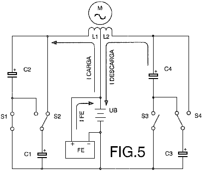 Fig.5 shows another embodiment in which an alternating current motor M is connected to two windings L1 and L2 so that during the connections in parallel of the capacitors C1 and C2, the latter are charged by means of the winding L1 at the same time that the capacitors C3 and C4, connected in series, are discharged by means of the winding L2 to the battery UB, the charging and discharging current circulating through the windings in the same direction. The capacitors C1 and C2 are then connected in series and the capacitors C3 and C4 are connected in parallel. The direction of the charging and discharging current of the capacitors is therefore reversed, thus producing at terminals of the motor an alternating voltage with a frequency that depends on the speed of switching of the contacts. The energy losses caused are compensated for from an external source FE, the sum of the current circulating from this source to the battery and the currents circulating through the two windings during charging and discharging of the capacitors being equal to zero. The battery is therefore not discharged as a result of the work developed by the motor. 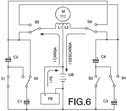 Fig.6 shows the connection of a direct current motor M to two windings L1 and L2 between the battery UB and the two pairs of capacitors C1 and C2 plus C3 and C4, so that during the connections in parallel two of the capacitors are charged by means of the winding L1, and during the simultaneous connections in series, the other two capacitors are charged by means of the winding L2 to the battery. Coinciding with the switching of the contacts S1, S2, S3 and S4, which connect to each pair of capacitors from parallel to serial and vice versa, the contacts S5 and S6 switch, polarising the windings of the motor so that the charging and discharging currents of the capacitors circulate in the same direction, producing a direct voltage. The sum of the current supplied from the external source FE and the charging and discharging currents of the capacitors is equal to zero, and thus there is no battery discharge Bob Boyce’s Electrolyser. Consider also, Bob Boyce’s very effective electrolyser system, which achieves twelve times the efficiency that Faraday considered to be the maximum possible. Faraday was no fool and he performed very high-quality tests and experiments an a methodical way, making solid observations and drawing conclusions which were respected by his colleagues. Yet here we have Bob Boyce outperforming Faraday by a factor of twelve times. Was Faraday wrong? Probably not. Is Bob wrong? Definitely not. How come then that they appear to disagree? Well, the Boyce system pulls in additional energy from the immediate environment by applying very high quality pulsing to a toroidal transformer wound with three very accurately positioned primaries and one very accurately wound secondary (the D9.pdf document provides full details of this). It also develops an oscillating magnetic field by using a hundred parallel, closely spaced steel plates. These magnetic oscillations enhance the process and place it outside the DC electrolysis which Faraday was examining. In passing, Shigeta Hasebe appears to get ten times the Faraday maximum on DC alone, but that is not the case as Shigeta uses strong permanent magnets to provide an additional energy input, so it is no longer strictly DC electrolysis as performed by Faraday. The Boyce arrangement is like this:  The output waveform from Bob Boyce’s triple-oscillator board is sharpened up by the use of carefully chosen opto-isolators, and that output would almost certainly drive Dave Lawton’s Meyer replication Water Fuel Cell. This pulsing system can also be used for battery charging and to avoid any chance of runaway feedback, it is recommended that it is used to charge a separate bank of batteries and is not used to charge the battery which is powering the circuit, although that has been done successfully. The combination of very sharp pulsing of an accurately wound toroid core composed of an iron powder matrix, is capable of drawing in very large amounts of extra power from the local environment that it is generally recommended that it is used with Bob's electrolyser cell which is capable of soaking up any excess energy surges. The extra energy drawn in is not always constant and surges can occur which can generate currents of 10,000 amps. It should be understood that this electrical current which we can measure is only the “losses” part of the real power surge which is in a form which we can’t measure as we have no instruments which can measure it directly. Consequently, the actual environmental power surge is far, far in excess of this 10,000 amps. It is strongly recommended that the electronics board and toroidal transformer are NOT connected to other equipment “to see what will happen”. It is also important not to arrange a pulsed, rotating magnetic field in the toroid by sequential pulsing of coils spaced around the toroid. These arrangements can generate power surges so great that the excess power not soaked up by the circuit is liable to form the ground-leader of a lightning strike. Bob experimented with this and was hit by a direct lightning strike. He was very lucky to survive being hit and he now works in a workshop which has metal walls and roof, and lightning grounding at each corner of the building, plus a separate ground for the equipment inside the building. A device like this is not a toy, and it demonstrates the incredible level of free-energy which can be tapped by quite simple devices if you know what you are doing. Please note, that if you do not have an electrolyser attached to the toroid to soak up any surges and voltage spikes, then I recommend that you connect a spark gap across the secondary winding and a varistor (spike protector) across the equipment which you are powering from the toroid, in an attempt to limit the level of the incoming power. Some additional information on what is happening would be useful here. If you fill a bath with water and place your open hand about a foot under water, palm upwards and allow the water surface to become smooth again. Moving your hand very slowly upwards out of the water causes minor disturbance of the water. However, if you do that very rapidly, some water will be lifted above the surface and come crashing down again, causing a major disturbance of the water. This is the sort of reaction which a voltage pulse has on the local environment and the size of the resulting effect depends almost entirely on the speed of that voltage pulse. If the voltage pulse rises very, very sharply, then the effect on the environment is large and the amount of power which flows in from the environment is large. Slowly rising voltage pulses have almost no effect. To give you some idea of what is meant by a sharply-rising voltage pulse, I am talking here about a pulse which has a rising edge which is too fast for a 150 MHz oscilloscope to show it. The oscilloscope will show the horizontal low-voltage line and the horizontal high-voltage line, but nothing in between as it just can't respond fast enough to show the rising edge. There are some things which are important to understand here. Don Smith states that each pulse causes an inflow of energy, so the faster those pulses are generated, the greater the rate of energy inflow. This is a commonsense view which anyone can easily understand. What is not so easy to understand is that Don states that the energy inflow is proportional to the square of the pulse rate, so double the rate, and the energy inflow goes up by a factor of four. Triple the rate, and the energy inflow becomes nine times greater. Even if you ignore that effect, it is obvious that if you double the rate that little packets of energy are drawn into your circuit from outside, that the inflow rate will definitely double. Don also states that increasing the voltage of the pulse has the same effect in increasing the energy inflow. A high-frequency waveform looks like this: 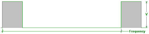 If you apply that frequency to Bob's toroid, then the toroid needs to be able to handle the waveform cleanly, without degrading it in any way. For this sort of application, an iron-dust toroid such as the MicroMetals product is essential. What many people have difficulty in seeing, is that even if the overall frequency of the signal is lower, as shown here:  in order for the rising edge of the waveform to be handled cleanly, the toroid has to be able to handle a very high frequency signal. The toroid doesn't "know" that the leading edge of the waveform is not going to be followed by a whole stream of very short, very fast, high-frequency pulses. So the toroid has to be able to handle high-frequency waveforms in order to deal with the very sharply rising leading edge which is essential for jolting the local electrical environment out of it's normal balance so that we can collect energy when it balances itself again. For this, an iron dust toroid is needed as steel laminations or ferrite are just not capable of doing the job. Don Smith. Don Smith is a very talented American who has understood all of Tesla's work and has produced literally dozens of practical devices based on his understanding. You will find more specific details in chapter 3, but in broad outline, a twelve-volt battery can be used to generate the pulsing magnetic field needed to nudge the local environment into providing massive amounts of electrical energy. The device described in detail in chapter 3, has an output of around 160 kilowatts, which is far, far more than any individual would need. In other words, it is a device which could easily power your home, and considering that an electric car needs about 65 kilowatts, one could easily power a vehicle, making it into a fuel-less mode of transport. This is not magic, just standard electrical theory being applied correctly for a change. The key component in many of Don's devices is the humble, commercial power supply used to drive neon sign displays. This module produces some 9,000 volts at a frequency of 35,100 Hz (cycles per second). As Don points out, when you double the pulsing frequency and double the pulsing voltage, the available power goes up by a factor of sixteen times, because the effect of both of these things is squared. You will recall that Bob Boyce is pulsing his toroid very sharply at 42,000 Hz and that high frequency has a major effect on the power produced in his system. Don then boosts his working voltage further with a step-up transformer called a Tesla Coil. This brings us into an area of massive power. People have the very mistaken idea that a Tesla Coil can only produce voltage and not current. The reality is that if the primary coil is positioned in the centre of the secondary coil, then the voltage and current produced will be roughly the same, and that is a very, very high level of power. One device of Don's looks like this: 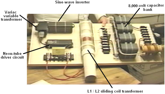 This prototype is actually more complicated than it needs to be. It uses three very high-voltage capacitors which are not necessary if you opt for a slightly different method of construction. However, in this version, the twelve-volt battery (which is not shown), powers a true sine-wave inverter in order to provide the mains voltage and frequency needed by the neon-tube driver circuit. The voltage limitations of the capacitors, in particular, the 8,000-volt output storage capacitors, make the 9,000 volt output of the neon-tube driver too much for safe usage. To deal with this, Don uses a Variac-style variable transformer to lower the voltage supplied to the neon-tube driver circuit, and this lets him limit the output voltage to the 8,000 volts of the output storage capacitors. A key detail is that the wire length in the turns of the short primary winding of the Tesla Coil is exactly one quarter of the wire length of the turns in the long secondary winding. This makes the coils resonate which is a vital factor in the operation. The final, exact tuning, can be done by sliding the primary coil to a slightly different position. In this prototype, Don chose to do the final fine tuning by attaching a small capacitor across each of the windings. This is not necessary. In the prototype shown above, Don then uses four diodes to rectify the output to DC to feed the storage capacitors. This results in an 8,000 volt supply which can provide 20 amps of current. That is an output power of 160 kilowatts, and is limited by the output capacitor voltage rating. Don points out that it is not necessary to do it that way and instead, a step-down transformer can be used to lower the output voltage and boost the available current. If this is done, then the voltage limitations disappear (provided that you are using very high-voltage cables) and so no Variac is needed and no high-voltage capacitors are needed either. There are two options. Either you can aim for a mains-voltage, mains-frequency, AC output, or you can produce a DC output and use an off-the-shelf inverter to run any mains equipment powered by the device. With the first option, Don connects a single resistor across the primary of the step-down transformer and that drags the frequency down to the wanted level, provided that the resistor has the right value: 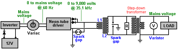 The alternative method which aims for a DC output does not need to alter the frequency: 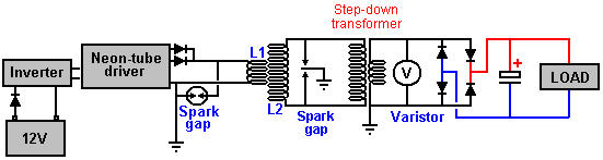 In both of these cases, the twelve volt driving battery can be charged continuously by part of the output power, and there are various ways of doing that. However, care needs to be taken that the battery is not overcharged as the input power is very low. You will notice the similarity between Bob Boyce's toroid system and Don Smith's Tesla Coil system. In each case, a very carefully wound circular winding is pulsed at high frequency, and in each case, substantial amounts of excess electrical power becomes available, flowing in from the surrounding environment, courtesy of the pulsating magnetic field. Tariel Kapanadze produced a similar style of device which is self-powered and produces a mains electricity output. He has demonstrated this for a TV documentary:  and any details available are in chapter 3. Steven Mark’s Toroidal Power Unit. Fairly recently, Steven Mark placed a video of a self-powered, circular coil device on YouTube. This device was demonstrated powering both itself and a 100 watt light bulb. If the video is still in place, then you can see it here.  I understand that Steven has sold the rights to his design and the building details have not been disclosed publicly. A number of attempts to replicate Steven’s device are being made at the present time, one of the best know is at this forum where interesting tests have been run on a variety of alternative constructions, mainly based on coils placed around a central Mobius loop. A Mobius loop is an arrangement where a wire loop has no starting point or ending point. The following diagram attempts to show how this is done, using a small inner loop inside a larger outer loop. In actual practice, the two loops are almost identical in size:  At the time of writing, although development work is continuing, nobody has replicated Steven’s TPU. The forum strategy is to place three coils around the Mobius loop and experiment with powering those coils with different forms of pulsed signals at different frequencies. The arrangement is like this: 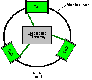 This is getting very close to Bob Boyce’s toroidal transformer system which picks up substantial amounts of excess power from the environment. Instead of using a Mobius loop, Bob uses a powdered-iron toroidal core, wrapped with the secondary winding around the whole of it’s length:  Then, on top of the secondary winding, three equally-spaced primary windings are wound on top of the secondary, and driven by electronics which is positioned inside the toroid as that is the place least affected by the magnetic fields produced by the system:  Let me stress again, that a toroidal core like these ones is potentially very dangerous, especially when pulsed with a high-frequency rotating magnetic field. An arrangement like that taps into the zero-point energy field which has unlimited power and power surges are liable to occur. Bob Boyce states that it is perfectly possible to get power surges of 10,000 amps which will not only burn out the equipment, but can also trigger a lightning strike directly at the equipment, and you, standing beside it. Bob was hit by a strike of this nature and you should remember that Nikola Tesla burnt out a whole power station when the input from the zero-point energy field exceeded the station’s capacity by a major factor. These things are not toys, and the power which is being tapped, is literally unlimited. Recently, Sterling Allan interviewed Jack Durban – see some of the details at Sterling’s web site and Jack made several statements about the Steven Mark device. You need to make up your own mind about how reliable the information coming from Jack actually is. Jack states that he has a “photographic memory” and yet he is unable to remember the number of an important patent which he had recently discussed with Sterling and unable to remember important details shown in his high-resolution video of Steven’s device operating. I know of no way of reconciling those statements, and that raises concerns for me personally. Jack also makes wholly unsupported and unnecessary allegations about the character and abilities of Steven which raises further doubts about the reasons for, and accuracy of the statements made. However, it seems necessary to note these statements, some of which are as follows: According to Jack, the device was not invented by Steven and he suspects it was based on Tesla’s patent No. 381,970 “System of Electrical Distribution” :  Jack also says that no patent was ever filed on Steven’s device and so long has now elapsed since public disclosure of the device, that it can no longer be patented. All the components were bought from Radio Shack, the shape is supposedly not important and was just made as a toroid because it was easy to wind that shape. He also says that it, and all replication attempts, get warm after a couple of minutes of use, but nineteen to twenty minutes into the operation, exponential thermal runaway takes place, causing the device to shut down completely. He also says that the device vibrated when in use although it contained no moving parts and there was no electronic circuitry used. Please remember that I am unsure of the reliability of these additional comments. Here is the Tesla patent mentioned, and which is being examined in detail on Stefan Hartmann’s overunity.com forum mentioned above: To all whom it may concern: Be it known that I, NIKOLA TESLA, from Smiljan Lika, border country of Austria-Hungary, now residing at New York, in the county and State of New York, have invented new and useful Improvements in Systems of Electrical Distribution, of which the following is a specification, reference being had to the drawings accompanying and forming a part of the same. This invention relates to those systems of electrical distribution in which a current from a single source of supply in a main or transmitting circuit is caused to induce by means of suitable induction apparatus, a current or currents in an independent working circuit or circuits. The main objects of the invention are the same as have heretofore been obtained by the use of these systems, that is, to divide the current from a single source, whereby a number of lamps, motors, or other translating devices, may be independently controlled and operated by the same source of current, and in some cases, to reduce a current of high potential in the main circuit to one of greater quantity and lower potential in the independent consumption or working circuit or circuits. The general character of the devices employed in these systems is now well understood. An alternating-current magneto-machine is used as the source of supply. The current developed thereby is conducted through a transmission circuit to one or more distant points at which the transformers are located. These consist of induction-machines of various kinds. In some cases, ordinary forms of induction-coil have been used with coil in the transmitting-circuit and the other in a local, or consumption circuit, the coils being differently proportioned according to the work to be done in the consumption-circuit – that is to say, if the work requires a current of higher potential than that in the transmission-circuit, the secondary or induced coil is of greater length and resistance than the primary, while, on the other hand, if a quantity current of lower potential is wanted, the longer coil is made the primary. In lieu of these devices, various forms of electro-dynamic induction-machines, including the combined motors and generators, have been devised. For instance, a motor is constructed in accordance with well-understood principles, and on the same armature are wound induced coils which constitute a generator. The motor-coils are generally of fine wire and the generator-coils of coarser wire, so as to produce a current of greater quantity and lower potential than the line-current, which is of relatively high potential, to avoid loss in long transmission. A similar arrangement is to wind coils corresponding to those described in a ring or similar core and by means of a commutator of suitable kind to direct the current through the inducing-coils successively, so as to maintain a movement of the poles of the core and of the lines of force which set up the currents in the induced coils. Without enumerating the objections to these systems in detail, it will suffice to say that the theory or the principle of the action or operation of these devices has apparently been so little understood that their proper construction and use have, up to the present time, been attended with various difficulties and great expense. The transformers are very liable to be injured and burned out, and the means resorted to for curing this and other defects have almost invariably been at the expense of efficiency. The form of converter or transformer which I have devised, appears to be largely free from the defects and objections to which I have alluded. While I do not herein advance any theory as to its mode of operation, I would state that, insofar as the principle of construction is concerned, it is analogous to those transformers which I have above described as electro-dynamic induction-machines, except that it involves no moving parts whatever, and is hence not liable to wear or other derangement, and requires no more attention than the other and more common induction machines. In carrying out my invention, I provide a series of inducing-coils and corresponding induced-coils, which by preference, I wind upon a core closed upon itself – such as an annulus or ring subdivided in the usual manner. The two sets of cols are wound side by side or superposed or otherwise placed in well-known ways to bring them into the most effective relations to one another and to the core. The inducing or primary coils wound on the core, are divided into pairs or sets by the proper electrical connections, so that while the coils of one pair or set to co-operate in fixing the magnetic poles of the core at two given diametrically-opposite points, the cols of the other pair or set – assuming, for sake of illustration, that there are only two – tend to fix the poles ninety degrees from such points. With this induction device I use an alternating-current generator with cols or sets of coils to correspond with those of the converter, and by means of suitable conductors, I connect up in independent circuits the corresponding coils of the generator and converter. It results from this that the different electrical phases in the generator are attended by corresponding magnetic changes in the converter; or, in other words, that as the generator-coils revolve the points of greatest magnetic intensity in the converter will be progressively shifted or whirled around. This principle I have applied under variously-modified conditions to the operation of electro-magnetic motors, and in previous applications, notably in those having Serial Nos. 252,132 and 256,561, I have described in detail the manner of constructing and using such motors. In the present application, my object is to describe the best and most convenient manner of which I am at present aware of carrying out the invention as applied to a system of electrical distribution; but one skilled in the art will readily understand from the description by the modifications proposed in said applications, wherein the form of both the generator and converter in the present case can be modified. In illustration therefore of the details of construction which my present invention involves, I now refer to the accompanying drawings. 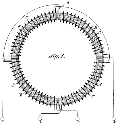 Fig.1 is a diagrammatic illustration of the converter and the electrical its connections. 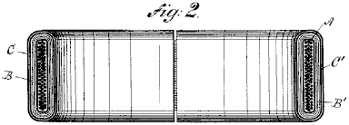
Fig.2 is a horizontal central cross-section of Fig.1  Fig.3 is a diagram of the circuits of the entire system, the generator being shown in section. The device is provided with suitable binding-posts, to which the ends of the coils are led. The diametrically-opposite coils B B and B’ B’ are each connected in series and terminated on the binding-posts 1, 2, 3 and 4. The induced coils are connected together in any desired manner. For example, as shown in Fig.3, C C may be connected in multiple arc when a quantity current is desired – as for running a group of incandescent lamps, D – while C’ C’ may be independently connected in series in a circuit including arc lamps or the like. The generator in this system will be adapted to the converter in the manner illustrated. For example, in the present case, I use a pair of ordinary permanent or electro magnets, E E, between which is mounted a cylindrical armature on a shaft, F, and wound with two coils G and G’. The terminals of these coils are connected, respectively, to four insulated contact or collecting rings, H H H’ H’, and the four line circuit-wires L connect the brushes K, bearing on these rings, to the converter in the order shown. Noting the results of this combination, it will be observed that at a given point of time, the coil G is in its neutral position and is generating little or no current, while the other coil, G’, is in a position where it exerts its maximum effect. Assuming coil G to be connected in circuit with coils B B of the converter, and coil G’ with coils B’ B’, it is evident that the poles of the ring A will be determined by coils B’ B’ alone; but as the armature of the generator revolves, coil G develops more current and coil G’ less, until G reaches its maximum and G’ its neutral position. The obvious result will be to shift the poles of the ring A through one quarter of its periphery. The movement of the coils through the next quarter of a turn, during which coil G’ enters a field of opposite polarity and generates a current of opposite direction and increasing strength, while coil G, in passing from its maximum to its neutral position, generates a current of decreasing strength and same direction as before, causes a further shifting of the poles through the second quarter of the ring. The second half-revolution will obviously be a repetition of the same action. By the shifting of the poles of the ring A, a powerful dynamic inductive effect on the coils C C’ is produced. Besides the currents generated in the secondary coils by dynamo-magnetic induction, other currents will be set up in the same coils in consequence of any variations in the poles of the ring A. This should be avoided by maintaining the intensity of the poles constant, to accomplish which, care should be taken in designing and proportioning the generator and in distributing the coils in the ring A and balancing their effects. When this is done, the currents are produced by dynamo-magnetic induction only, the same result being obtained as though the poles were shifted by a communicator with an infinite number of segments. The modifications which are applicable to other forms of converter are in many respects applicable to this. I refer more particularly to the form of the core, the relative lengths and resistances of the primary and secondary coils, and the arrangements for running or operating them. The new method of electrical conversion which this system involves, I have made the subject of another application, and I do not claim it here. Without limiting myself therefore to any specific form, what I claim is –
An interesting suggestion for a Steven Mark replication, comes from “tao” of the web-based forum located here and reproduced here with his kind permission. Here, the central core is a coil of wire. Bob Boyce has found that it is essential to use specialist wire for the windings of his toroidal transformer. The only viable material is solid-core copper wire which has a coating of silver and an outer covering of teflon. This is particularly interesting as that matches exactly, the materials used by Ed Gray inside his power tubes, where solid copper rods have their operational tips coated with silver. Silver is clearly a strategic material in this operation (as is carbon, which Ed also used inside his power tubes). Consequently, I would suggest that solid-core, silver-plated, teflon-covered wire would be a realistic choice for the central ring of tao’s projected design: 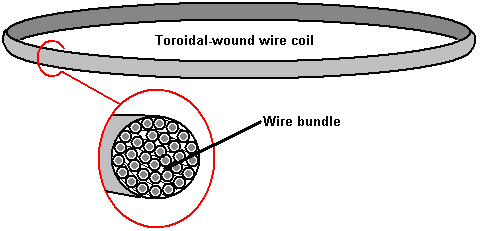 On top of the toroidal wind of wire, the bundle is wrapped in slightly overlapping pulsing coils. The theory of operation is that one coil is pulsed. This creates a strong magnetic field which causes the movement of environmental energy along the section of the toroid coil which is inside the pulse coil. This energy flow can be thought of as being electrons flowing through the wire of the toroid. While electrons do actually flow through copper wire, the rate of flow is millions of times slower than the flow along the surface of the wire. However, strictly speaking, we are really looking for zero-point energy to flow “in” the toroidal coil. Here again, we are not being entirely accurate as that energy does not flow in or on the wire at all, but instead, it flows along the magnetic field formed around the wire. As current in the toroidal coil intensifies, the magnetic field along its length increases, further directing the flow of “cold” electricity which we want. The zero-point field energy flow is created by the imbalance of the local energy field by the magnetic “dipole” created by the current flowing through the pulse coil. This is exactly the same situation as arises when a battery “dipole” unbalances the local field, creating broken symmetry and causing massive energy flows to radiate out from each pole of the dipole. A minute fraction of this massive energy flow happens to ride along the magnetic field around the toroidal wire coil, which is exactly what we want. However, the strategy is to have minimum current flow in the pulsing coils, so the idea is to cut off the voltage applied to the pulse coil before actual current has an opportunity to flow. In theory, we should get the drive which we want, without any current flowing at all - drive from just voltage potential alone. From an electronics point of view, this is a very tall order indeed, especially since there must be no reverse voltage at the time of switch off. Nikola Tesla used a spark gap for pulses of that duration, but operating a spark gap is a very long way from a current-less drive pulse. Anyway, tao’s idea is to have three, six, nine or twelve pulse coils around the circumference of the toroidal coil. These coils should overlap slightly at each end. For the purpose of this explanation, just three coils are shown here:  If pulse coil 1 is powered up, it causes an energy flow in a clockwise direction, through the pulse coil and therefore, along that section of the toroidal coil. This is a pulse of very short duration. The energy flow will be at 186,000 miles per second or about 300,000,000 metres per second. If the circumference length of the toroidal coil is one metre, then the energy flow through that third of the circumference will be completed in just under one nanosecond. The idea is then to cut off the drive to pulse coil 1 and power pulse coil 2 in order to continue the drive for the energy which has just flowed through pulse coil 1. Then, after one more nanosecond, pulse coil 2 is powered down and pulse coil 3 is pulsed. This is to produce a continuously rotating magnetic field around the circumference of the toroidal coil. This is a nice theory, but there is no obvious way of implementing it in practice. Even providing a separate circuit for each pulse coil, each circuit would need to generate a 1 nanosecond pulse every 3 nanoseconds. That will not be done with a mechanical switching system, and no solid-state solution springs to mind. The waveform needs to have very sharply rising and falling edges and a frequency of some 900 Mhz, which is not an easy circuit to produce. The Ed Gray Power System. The power tube presented to the public by Edwin Gray snr. operates by generating a series of very short, very sharp pulses using a spark gap. This device is reputed to have a power output which is one hundred times that of the power input. Ed Gray and his electric pulse motor are very famous, but as far as I am aware, nobody has successfully replicated this claimed performance. Further, an in-depth examination of the background details by Mr Mark McKay have turned up a number of facts which present a very different picture, and while it is perfectly correct to say that spark-gap pulses generate a good waveform for shocking the local zero-point energy field into the sort of imbalance which can provide a massive power inflow into a device or circuit, we need to be careful to get the full facts in this case.  First, let us put the whole thing in its proper perspective. In May 1973, Cal-Tech in the US performed an independent assessment of an engine provided to them by Edwin Gray. They measured the input and the output and certified that the output power was 275 greater than the input power. This demonstrates clearly that excess power can be drawn into an engine and provide a performance which can power both the engine as well as doing additional useful work. Having said that, it needs to be made clear that Edwin Gray did not build that small motor, did not understand how it worked, nor did he ever disclose the design in any of the patents which he obtained afterwards. We need to follow the sequence of events and notice when each thing happened. The history is as follows: In 1957, a Russian immigrant to the USA, one Alexei Poppoff, showed Edwin Gray a circuit which he said that he had been shown by Nikola Tesla. Edwin Gray did not understand the circuit and had no idea how to create anything useful based on it. He then joined up with his next-door neighbour Marvin Cole, who held a Masters degree in Mechanical Engineering and who, unlike Gray, was able to understand the circuitry. In 1958, Ed Gray (shown above) left the Los Angles area in a hurry. From 1958 to 1972 Marvin Cole, working alone, designed and built ever more powerful prototype engines, and it was a small one of these which was tested by Cal-Tech. In this period, Marvin also developed ever more powerful power supplies, which are the really important item in all of this. In 1967, Ed Gray rejoins Marvin Cole and together from 1967 to 1972, they solicited venture capital and promoted the technology. Early in 1972, Marvin Cole disappeared and never saw Gray again. It is not clear if he was intimidated, died, or just did not want to be involved in all the publicity and effort needed to turn the prototype engines into a commercial product. No matter what the reason, the result was that Edwin Gray was suddenly disconnected from the brains behind the project, and that left him in a very difficult position. He didn't want to let go of the dream of becoming rich through this spectacular development, and so he tried to continue the development on his own. As already mentioned, in May of the following year (1973), Gray had a small Marvin Cole motor independently third-party tested at the famous Cal-Tech laboratory in Los Angles, where a measured input of just 27 watts produced a measured output of 10 horsepower (7460 watts). The objective was to provide solid evidence of a new technology which was capable of changing the world and so would attract investors. To further boost his image and convince potential investors, in that same year of 1973, Edwin staged demonstrations which jumped electromagnets up into the air, showing the strength of the power which drove the Marvin Cole engines. It is very important to understand that all of Edwin Gray's patents were applied for after the departure of Marvin Cole. These do not disclose the technology tested by Cal-Tech and it must be understood that Edwin was very much afraid of revealing anything important in any of the patents in case some other person would understand the things which were a mystery to him and snatch away the prize of commercial success. So, please be aware that the patents where applied for solely to encourage investors and most definitely not to show any significant details. Edwin then assembled a small team of people to attempt to understand and advance the work of Marvin Cole. However, the subsequent changes to the Cole implementations did not result in genuine, reliable working motors due to Gray's lack of understanding of the underlying energy-tapping methods used by Cole. The Power Tube shown in Gray's patents has never been shown to provide the COP=100 energy performance which is sometimes mentioned, nor did it form part of Marvin Cole's system. Edwin Gray shows three of these Power Tubes driving one (failed version) motor, which is in direct conflict with Marvin Cole's technique which had 24 separate power supplies driving the motor. Please understand that the power-gathering mechanism of the Cole system is the key feature of all of the successful systems. Unfortunately, as far as I am aware, that technology has never been disclosed. Just to clarify the differences, let me briefly outline my understanding of what Edwin Gray put forward as the power-gathering system of the motors which he attempted to develop after he parted company with Marvin Cole. Edwin shows three Power Tubes connected to the engine like this: 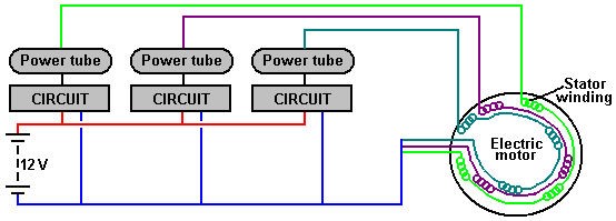 Here, three separate sets of electromagnets inside the motor are pulsed in sequence by three separate identical circuits, each driving the electromagnets via a power Tube. Marvin Cole's system used twenty-four separate power-gathering circuits which drove twenty-four separate electromagnets inside the motor (Power Tubes were not used). You may wish to try Edwin's Power Tube for yourself, so let me explain the basic details as I understand them. The overall circuit is like this: 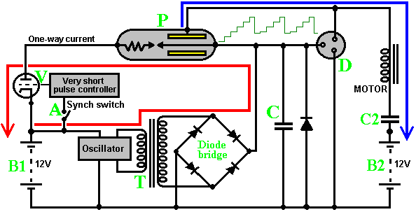 You will notice that the power driving the load does not come from the battery as the battery circuit produces the spark and nothing else. The load is driven by power picked up on the copper shells around the half inch (12 mm) diameter copper rod spark-gap electrode with its silver coated tips. The circuit supposedly operates as follows. The driving 12V battery “B1”, continuously powers an oscillator which uses transformer “T” to step the voltage up to a high level. This high voltage is full-wave rectified by a bridge of high-voltage diodes, and the resulting DC voltage is fed to capacitor “C”. If any malfunction causes this DC voltage to get too high for safety, the discharge contacts “D” cause the voltage to discharge via a spark to the earth connection. Under normal circumstances, the high voltage on “C” creates a spark in the power tube “P” when it’s circuit is completed by the closing of switch “A”, which is used to synchronise the power pulse to the rotation position of the electric motor windings. The switch drives a monostable circuit which delivers a very short enabling pulse to “V” the “one-way current switch” which is a powerful electronic triode valve. These days, it is very difficult to get a valve of that type and the best source is probably the power output valve from a World War Two radio transmitter. The power tube “P” has a resistor shown in it. This was actually a block of carbon, and as such, will have had minimal electrical resistance. However, several different devices which appear to have COP>1 power outputs use a spark gap associated with a carbon electrode, so there may well be a second effect coming into play here. A key factor in this circuit is the fact that the power which drives the motor does not come from this electrical circuit at all, but from the apparently disconnected cylinders inside power tube “P”. This power is “cold” electricity, flowing into the circuit from the local environment. Remember that Floyd Sweet in his first measured test had a solid 500 watt electrical output from a power input of just 0.31 of a milliwatt. In this circuit, the “MOTOR” represents just one of the coil windings inside the electric motor and instead of the power flowing through the motor being fed to ground as normal, it is fed to the +12 volts of battery “B2”. The objective was to charge battery “B2”, the charging current being limited by capacitor “C2”, the idea being that “B1” and “B2” could be swapped over when “B1” became discharged. This arrangement was soon discontinued and battery “B2” was charged from a standard car alternator driven by the engine in an entirely conventional manner. A rapid and abrupt electrical discharge is produced by generating a spark, and power pick-up is achieved by two copper cylinders surrounding the conductor which carries the spark current. There is more than one way of doing this. In the following diagram, the spark gap is shown exposed to make it easier to see, but in practice, the perforated copper shells extend to cover the spark gap: 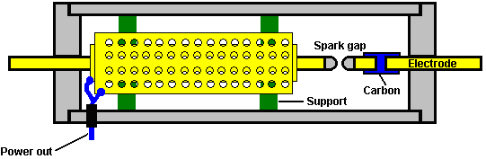 A full and detailed description of how it is believed that “Ed Gray’s” system works is given in Peter Lindemann’s book “The Free Energy Secrets of Cold Electricity” which is available via this website. Tesla used this spark gap method with spark quenching provided by a strong magnetic field at right angles to the spark, in order to get really high-quality DC pulses with durations of one microsecond or less. Pulse trains of individual pulses with very short durations produce heat, spontaneous lighting, cooling, etc. depending on the frequency of the pulsing. The power tube is placed around a heavy-duty copper conductor which is pulsed, unbalancing the zero-point energy field and a tiny part of the resulting energy flow as the field moves back into equilibrium again, is captured by the surrounding perforated copper shells. While the switching valve in the electronics circuit looks like a very difficult component to come by, the possibility of constructing one yourself should be considered. Essentially, a thermionic valve is a simple device. A heated filament at one end of the tube emits electrons. A high voltage along the length of the tube provides an electrical urge for those electrons to flow along the tube. A metal grid between the heated filament and the electrode at the far end of the tube can be used to prevent that current flow by connecting an opposing voltage to that grid. It is that grid voltage which is turned off very briefly to provide the current pulse to one set of motor windings. A seeming obstacle is producing the glass envelope for the valve, but there is actually no need for the valve to have a glass container and a wide range of other materials can be used. Another obstacle is creating a vacuum inside the valve housing, but it has been stated that the main reason why these valves have a vacuum inside them was mainly commercial, namely, an attempt to encourage people not to make their own. It is said that there is no reason why a thermionic valve should not have air inside it – the current flow is not a spark. I have no idea how accurate, or inaccurate, this information on valve construction is, but I strongly suspect that it is correct. Marvin Cole's power system produced "cold electricity" which could power lights and other devices. It was frequently demonstrated that the output was not conventional electricity and powered light bulbs which were placed under water and at the same time, it was quite safe for a hand to be put into that same water along with the lit bulb. The glass of the conventional bulbs used in these demonstrations would have shattered when placed under water if they had been powered by conventional "hot electricity" as the sudden change in temperature would have broken the glass. Powered as they were by "cold electricity", they ran cool and so there was no stress on the glass when submerged in water. The construction of the pick-up tube is not particularly difficult. It is comprised of a teflon (plastic) cylinder of about 80 mm diameter with teflon plates at each end, grooved to hold the pick-up cylinders in place. A pair of 12 mm diameter copper rods are positioned down the centre of the cylinder and provided with a means to adjust the gap between them where they meet. The rod ends form the spark gap and these ends are plated with silver. One rod has a graphite block inserted in it, using a push-fit connection into slots cut in the bar. This carbon insert is supposedly a resistor, but in fact it is an important part of the excess energy generation system. In some successful constructions of the tube an 8-inch long, half-inch diameter carbon rod with a silver tip, is used for one of the electrodes. The two or three cylinder shells which pick up the Radiant Energy, are constructed from copper sheet. The gap between the outside of one cylinder and the inside of the surrounding cylinder is about 6 mm. These cylinders are more effective if they have a matrix of holes drilled in them. They are connected together electrically and the connection is led out through the teflon casing to feed the load circuit. The cylinder contains air rather than a vacuum or an inert gas. The copper cylinders are held in place by push-fit supports, one set positioned between the outside of the smaller cylinder and the inside of the larger cylinder. The second set are placed between the outside of the larger cylinder and the inside of the housing tube: 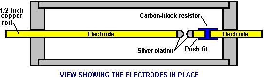 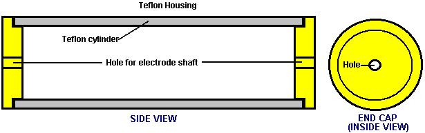 The power tube is constructed this way because the Radiant Energy wave generated by the sharp pulse of current through the electrodes, radiates out at right angles to the electrodes. Peter Lindemann points out that Ed Gray’s power conversion tube circuit is effectively a copy of Nikola Tesla’s circuit for doing the same thing: 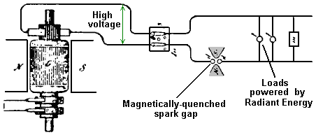 This was disclosed by Tesla in his ‘Philadelphia and St Louis’ lecture in 1893 and shows how loads can be powered when a high voltage source is pulsed by a magnetically-quenched sparks - this creates DC pulses of very short duration. 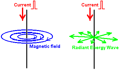 The diagram above, illustrates the difference between the Magnetic field generated around a conductor fed with a pulse of Direct Current and the Radiant Energy waves created by that pulse. If a sharp current pulse is driven down a vertical wire, it causes two different types of field. The first field is magnetic, where the lines of magnetic force rotate around the wire. These lines are horizontal, and rotate clockwise when viewed from above. The magnetic field remains as long as the current flows down the wire. The second field is the Radiant Energy wave. This wave will only occur if the current pulse is in one direction, i.e. it will not occur if the wire is fed with alternating current. The wave radiates out horizontally from the vertical wire in every direction in the form of a shock wave. It is a one-off event and does not repeat if the current in the wire is maintained. The Radiant Energy briefly unbalances the zero-point energy field and that causes an energy flow as the field moves back into equilibrium again. A tiny fraction of this massive, brief energy flow can be picked up and that collected energy is more than 100 times greater than the energy needed to generate the spark which triggered the energy flow in the first place. This is the energy which the tube was designed to collect. Consequently, the tubes are fed with a train of high-intensity, short-duration, DC pulses to generate repeated waves of Radiant Energy. It is the pick-up of the resulting excess energy which allows the motors run without the need for the batteries to be charged by any conventional source of current. The Radiant energy wave is not restricted to a single plane as shown in the diagram above, which is intended to indicate the difference between the electromagnetic field circling around the wire, and the Radiant Energy field which radiates away from the wire. Both of these fields occur at all points along the full length of the wire as shown here: 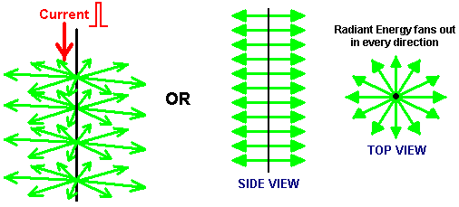 Radiant Energy, when converted to electrical power, produces a different kind of electrical power to that produced by batteries and by the mains supply. Power a motor with conventional electricity and it gets hot under load. Power the same motor by Radiant Energy electricity and under load the motor gets cold. Really overload it by stalling it and the motor housing is likely to be covered with frost. That is why this form of electricity is referred to as “cold” electricity. In his book “Cold War Secrets - HAARP and Beyond”, Gerry Vassilatos quotes research work done in this area by Tesla and others: Tesla’s Experiments: In 1889 Tesla began experimenting with capacitors charged to high voltages and discharged in very short time intervals. These very short pulses produced very sharp shockwaves which he felt across the front of his whole body. He was aware that closing a switch on a high-voltage dynamo often produced a stinging shock. This was believed to be static electricity and it occurred only at switch-on and only for a few milliseconds. However, in those few milliseconds, bluish needles of energy stand out from the electrical cables and they leak to ground, often through the bodies of any people standing nearby, causing immediate death if the installation is large. While the generators of that time were rated at some thousands of volts, these discharges were millions of volts in intensity. The generator problem was eliminated by the used of highly insulated switches which were provided with a very large ground connection.  Tesla was intrigued by this phenomenon which appeared to match the effect of his capacitor discharges. He calculated that the voltages produced were hundreds of times greater than could be supplied by the capacitor or generator. It was clear that the power supplied was being amplified or augmented in some way, but the question was, from where was the extra energy coming? Tesla continued to investigate through experiments, taking precautions against the high voltages being produced. He was soon able to produce these shockwaves whenever he wanted to. The shockwaves produced a stinging sensation no matter where he stood in his laboratory, and hands and face were particularly sensitive to the wave. These waves radiated out and penetrated metal, glass and every other kind of material. This was clearly not an electromagnetic wave, so he called the new wave ‘Radiant Electricity’. Tesla searched the literature to find references to this radiant energy but he could not find much. In 1842, Dr. Joseph Henry had observed that steel needles were magnetised by a Leyden Jar spark discharge located on a different floor of the building. The magnetising wave had passed through brick walls, oak doors, heavy stone and iron flooring and tin ceilings to reach the needles located in a vault in the cellar. In 1872, Elihu Thomson took a large Ruhmkorrf Spark Coil, attached one pole of the coil to a cold-water pipe and the other pole to a metal table top. This resulted in a series of massive sparks which electrified the metal door knob of the room and produced the stinging shockwaves which Tesla was investigating. He found that any insulated metal object anywhere in the building would produce long continuous white sparks discharging to ground. This discovery was written up briefly in the Scientific American journal later that year. Tesla concluded that all of the phenomena which he had observed, implied the presence of “a medium of gaseous structure, that is, one consisting of independent carriers capable of free motion - besides the air, another medium is present”. This invisible medium is capable of carrying waves of energy through all substances, which suggests that, if physical, its basic structure is much smaller than the atoms which make up commonplace materials, allowing the stream of matter to pass freely through all solids. It appears that all of space is filled with this matter. Thomas Henry Moray demonstrated this energy flow passing through glass and lighting standard electric light bulbs. Harold Aspden performed an experiment known as the “Aspden Effect” which also indicates the presence of this medium. Harold made this discovery when running tests not related to this subject. He started an electric motor which had a rotor mass of 800 grams and recorded the fact that it took an energy input of 300 joules to bring it up to its running speed of 3,250 revolutions per minute when it was driving no load. The rotor having a mass of 800 grams and spinning at that speed, its kinetic energy together with that of the drive motor is no more than 15 joules, contrasting with the excessive energy of 300 joules needed to get it rotating at that speed. If the motor is left running for five minutes or more, and then switched off, it comes to rest after a few seconds. But, the motor can then be started again (in the same or opposite direction) and brought up to speed with only 30 joules provided that the time lapse between stopping and restarting is no more than a minute or so. If there is a delay of several minutes, then an energy input of 300 joules is needed to get the rotor spinning again. This is not a transient heating phenomenon. At all times the bearing housings feel cool and any heating in the drive motor would imply an increase of resistance and a build-up of power to a higher steady state condition. The experimental evidence is that there is something unseen, which is put into motion by the machine rotor. That “something” has an effective mass density 20 times that of the rotor, but it is something that can move independently and take several minutes to decay, while the motor comes to rest in a few seconds. Two machines of different rotor size and composition reveal the phenomenon and tests indicate variations with time of day and compass orientation of the spin axis. One machine, the one incorporating weaker magnets, showed evidence of gaining strength magnetically during the tests which were repeated over a period of several days. This clearly shows that there is an unseen medium which interacts with everyday objects and actions, and confirms Tesla’s discovery. Tesla continued to experiment and determined that a very short uni-directional pulse is necessary to generate the radiant energy wave. In other words, an alternating voltage does not create the effect, it has to be a DC pulse. The shorter the pulse time and the higher the voltage, the greater the energy wave. He found that using a capacitor and an arc discharge mechanism with a very powerful permanent magnet placed at right angles to the spark, improved the performance of his equipment by a major factor. Additional experiments showed that the effects were altered by adjusting the duration of the electrical pulse. In each instance, the power of the radiated energy appeared to be constant irrespective of the distance from his apparatus. The energy was in the form of individual longitudinal waves. Objects placed near the equipment became powerfully electrified, retaining their charge for many minutes after the equipment was switched off. Tesla was using a charging dynamo as a power source and he found that if he moved his magnetic discharger to one side of the dynamo, the radiant wave was positive. If he moved the magnetic discharger towards the other side of the dynamo, the radiant wave became negative in sign. This was clearly a new electrical force which travelled as light-like rays, showing them to be different in nature to the electromagnetic waves of Maxwell. Investigating the effects of adjusting the duration of the pulses, Tesla found that a pulse train which had individual pulses with durations exceeding 100 microseconds, produced pain and mechanical pressures. At this duration, objects in the field visibly vibrated and were even pushed along by the field. Thin wires subjected to sudden bursts of the radiant field, exploded into vapour. When the pulse duration was reduced to 100 microseconds or below, the painful effect was no longer felt and the waves are harmless. With a pulse duration of 1 microsecond, strong physiological heat was felt. With even shorter pulse durations, spontaneous illuminations capable of filling rooms with white light, were produced. Even shorter pulses produced cool room penetrating breezes with an accompanying uplift in mood and awareness. These effects have been verified by Eric Dollard who has written about them in some detail. In 1890, Tesla discovered that if he placed a two-foot long single-turn deep copper helix coil near his magnetic disrupter, the thin-walled coil developed a sheath of white sparks with long silvery white streamers rising from the top of the coil. These discharges appeared to have much higher voltages than the generating circuit. This effect was greatly increased if the coil was placed inside the disrupter wire circle. The discharge seemed to hug the surface of the coil with a strange affinity, and rode up its surface to the open end. The shockwave flowed over the coil at right angles to the windings and produced very long discharges from the top of the coil. With the disrupter charge jumping one inch in its magnetic housing, the coil streamers were more than two feet in length. This effect was generated at the moment when the magnetic field quenched the spark and it was wholly unknown at that time. This train of very short uni-directional pulses causes a very strange field to expand outwards. This field resembles a stuttering electrostatic field but has a far more powerful effect than would be expected from an electrostatic charge. Tesla was unable to account for the enormous voltage multiplication of his apparatus using any of the electrical formula of his day. He therefore presumed that the effect was entirely due to radiant transformation rules which would have to be determined through experimental measurements. This he proceeded to do. Tesla had discovered a new induction law where radiant shockwaves actually auto-intensified when encountering segmented objects. The segmentation was the key to releasing the action. Radiant shockwaves encountered a helix and “flashed over” the outer skin, from end to end. This shockwave did not pass through the windings of the coil but treated the surface of the coil as a transmission path. Measurements showed that the voltage increase along the surface of the coil was exactly proportional to the length travelled along the coil, with the voltage increase reaching values of 10,000 volts per inch of coil. The 10,000 volts which he was feeding to his 24 inch coil were being magnified to 240,000 volts at the end of his coil. This was unheard of for simple equipment like that. Tesla also discovered that the voltage increase was mathematically linked to the resistance of the coil winding, with higher resistance windings producing higher voltages. Tesla then began to refer to his disrupter loop as his special “primary” and to the long helical coil as his special “secondary” but he never intended anyone to equate these terms to those referring to electromagnetic transformers which operate in a completely different way. There was an attribute which baffled Tesla for a time. His measurements showed that there was no current flowing in the long copper ‘secondary’ coil. Voltage was rising with every inch of the coil, but there was no current flow in the coil itself. Tesla started to refer to his measured results as his “electrostatic induction laws”. He found that each coil had its own optimum pulse duration and that the circuit driving it needed to be ‘tuned’ to the coil by adjusting the length of the pulses to give the best performance. Tesla then noticed that the results given by his experiments paralleled the equations for dynamic gas movements, so he began wondering if the white flame discharges might not be a gaseous manifestation of electrostatic force. He found that when a metal point was connected to the upper terminal of the ‘secondary’ coil, the streamers were directed very much like water flowing through a pipe. When the stream was directed at distant metal plates, it produced electronic charges which could be measured as current at the receiving site but in transit, no current existed. The current only appeared when the stream was intercepted. Eric Dollard has stated that this intercepted current can reach several hundred or even thousands of amps. Tesla made another remarkable discovery. He connected a very heavy U-shaped copper bar directly across the primary of his disrupter, forming a dead short-circuit. He then connected several ordinary incandescent filament bulbs between the legs of the U-shaped bar. When the equipment was powered up, the lamps lit with a brilliant cold white light. This is quite impossible with conventional electricity, and it shows clearly that what Tesla was dealing with was something new. This new energy is sometimes called “cold electricity” and Edwin Gray snr. demonstrated how different it is by lighting incandescent-filament bulbs directly from his power tube, submerging them in water and putting his hand in the water. Cold electricity is generally considered to be harmless to humans. Ed Gray’s power tube operates by generating radiant electricity waves by using a spark gap, and collecting the energy using three encasing copper cylinders surrounding the spark gap. The cylinders are drilled with many holes as that enhances the pick-up and the load is driven directly from the current in the cylinders. When lighting bulbs, Ed used an air-cored transformer made of just a few turns of very heavy wire. I, personally, am aware of two people who have independently reproduced Ed’s power tube. Tesla viewed the streamers coming off his coils as being wasted energy so he tried to suppress them. He tried a conical coil but found that this accentuated the problem. He then tried placing a copper sphere at the top of his coil. This stopped the streamers but electrons were dislodged from the copper sphere, creating really dangerous conditions. This implied that metals generate electron flows when struck by the coil streamers (as had been seen when the streamers had been aimed at remote metal plates and current was generated as a result). Tesla designed, built and used large globe lamps which required only a single external plate for receiving the radiant energy. No matter how far away these lamps were from the radiant source, they became brilliantly lit, almost to the level of an arc lamp and far, far brighter than any of the conventional Edison filament lamps. By adjusting the voltage and the pulse duration of his apparatus, Tesla could also heat or cool a room. Tesla’s experiments suggest that a method of extracting free-energy is to use a Tesla coil which has a metal spike instead of the more common metal sphere at the end of the ‘secondary’ coil. If the Tesla coil is fed with sufficiently short uni-directional pulses and the ‘secondary’ coil pointed at a metal plate, then it should be possible to draw off serious levels of power from the metal plate, just as Tesla discovered. This has been confirmed by Don Smith who uses two metal plates separated by a layer of plastic dielectric, forming a capacitor. He states that a well designed Tesla coil is capable of producing currents as high as the voltages and he demonstrates a hand-held 28 watt Tesla Coil played on the first plate producing a substantial continuous spark discharge between the second plate and ground. I estimate that the spark produced would have to be thousands of volts at a significant current, which puts it in the kilowatt range, like most of Don's other devices. Don's video Don's patent is in Chapter 3 and here is Don's pdf document in which he explains many of his high-power designs. 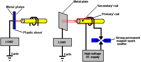 Don also points out that the positioning of the primary coil relative to the secondary coil of a Tesla Coil determines the amount of current which can be provided. Contrary to most opinion, it is possible to have Tesla Coil current as high as the voltage. Don always stresses that you have the option of picking the electrical component (as conventional science has done) which leads to "heat death" while the alternative option of selecting the magnetic component makes "the world your oyster". With a magnetic ripple imposed on the zero-point energy field, which Don prefers to call the 'ambient background energy', you can make as many electric conversions as you wish, without depleting the magnetic event in any way. In other words, you can draw off serious amounts of current from capacitor plates positioned at right angles to the magnetic flow, and every additional pair of plates gives you an additional source of major current without any need to increase the magnetic disturbance in any way. With his single metal plate, Tesla mentioned currents of a thousand amps being available. Please remember that a Tesla Coil produces seriously high voltages and is not a toy. Great care is needed around a Tesla Coil so, when it is running, keep well away from it. Don also states that the collection and transfer of energy requires temporary storage which occurs as the capacitors and coils of a resonant circuit are cycled on and off. The frequency at which the capacitors and coils are pumped, determines the amount of electrical energy that moves onwards. The amount of Energy transferred relates directly to the density of lines of magnetic flux present. The Kinetic Energy formula is helpful in establishing the amount of energy present. This formula points to mass multiplied by the square of the velocity. In the case of electrical energy, intensity of voltage and amperes multiplied by cycles per second, replace velocity. Note that the "acceleration" of the Voltage and the Amperage, increases in a non-linear fashion as the Law of Squares applies, with each unit of increase causing a squaring of the flux lines present. In resonant air-core coil energy transfer, the increase in flux lines present disturbs more electrons than previously and this results in greater output energy than input energy being present and available. Energy stored, multiplied by the cycles per second, is the energy being pumped by the system. Capacitors and inductors (coils) temporarily store electrons. Capacitor formula: W = 0.5 x C x V2 x Hz where: W is the energy in Joules (Joules = Volts x Amps x seconds) C is the capacitance in Farads V is the voltage Hz is the cycles per second Inductor formula: W = 0.5 x L x A2 x Hz where: W is the energy in Joules L is the inductance in Henrys A is the current in amps Hz is the frequency in cycles per second Both one Henry and one Farad equal one volt. The higher the frequency, including the squaring of the flux lines, causes a large increase in the amount of energy being produced. This, combined with the use of a resonant energy induction system (all electrons moving in the same direction at the same time), make the move into COP>1 practical. The damping process of conventional electrical power generation, has all of the available electrons bouncing randomly, mostly cancelling out each other, and so the useful energy available is only a very small percentage of the energy which is present. In a resonant induction system, a very high percentage of the energy present is useful. When resonant, (ohms-impedance-Z) becomes zero and all of the energy present becomes available, undegraded. Ohms is load or wasted energy and amperes is the rate of that wasting. Now, apply this information to an air-core coil resonant transformer energy system. L-1 and L-2 coils are now present. L-1 has fewer turns and is several times the diameter of L-2. Input from a 12-volt 'gelcel' high-voltage laser module, produces 8,000 volts with low (wasted energy) amperage into 4 turns of coil L-1. Each turn of L-1 then acquires 2,000 volts of resonant potential. Each turn of L-2 is then exposed to an electric flux of 2,000 volts. Each turn at the bottom end of L-2 acquires 2,000 volts. The flux lines are squared and are additive as the voltage and amperage progress towards the top end of L-2's many turns. A huge number of flux lines which were not previously present, occur at the top end of L-2. These flux lines excite the electrons nearby in it's earth and air and groundings. This high level of excitement above the ambient, causes a large number of electrons to become available, electrons which previously, were not part of the energy present. At this point, large amounts of excess energy is present. This COP>1 device produces energy at radio frequencies in the megahertz range and this allows it to be small in size and yet produce large amounts of energy. A megawatt sized unit will sit comfortably on a breakfast table. The energy is changed to direct current, and then, to the desired working frequency. The energy powering these devices is drawn from the surrounding energy field and is not conventional electricity and it does not flow through the wire of the ‘secondary’ coil, but instead, it runs along the outside of the coil and through space to strike the surface of the metal plate, where it generates conventional electric current. Thomas Henry Moray demonstrated that this energy flowing along the outside of the wire can pass through glass without being affected in any way. In his 1995 paper Don Smith presents the following diagram:  While Tesla’s experiment used a metal plate, he patented (US 512,340) a coil type which he said is very effective in picking up this radiant energy. This "pancake" coil type goes by the rather impressive name of “bi-filar serial-connected coil”, which, despite it's impressive name is not difficult to wind using two separate strands of wire as shown here: 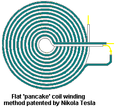 If a strong magnetic field is positioned across the spark gap as shown above, it sharpens the cut-off of the spark and enhances the uni-directional character of the pulse of current. It should be remembered that if a very short sharp pulse of uni-directional current such as is produced by a spark jumping across a spark gap as in the arrangement shown above, occurs in a conductor, then a strong wave of radiant energy radiates out in a plane at right angles to the pulse of current. This radiant energy wave is quite different from the electromagnetic field generated around the wire carrying the pulse of current. In the Tesla coil arrangement shown above, it should be possible to gather additional free energy through one or more co-axial (like layers of an onion) cylindrical coils around the spark gap leads. These coils will be better if they are would as bi-filar serially-connected coils, which just means that the wire used to wind them is doubled over from its mid point before the coil is wound. The reason for this arrangement is that the magnetic field component of the coils is (nearly) zero as the current flowing through the wire is flowing in opposite directions in alternate turns, and so the magnetic fields produced should cancel out: 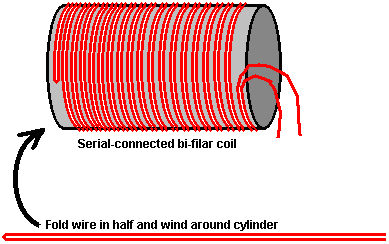 Tesla was granted US Patent 685, 957 “Apparatus for the Utilisation of Radiant Energy” in which he shows various ways of handling the energy collected by the metal plate. It is likely that the pick-up techniques shown in the patent of Hermann Plauston, which is in the Appendix, would also work very effectively with this collected energy. Old patents sometimes mention a “condenser” which is the original term for what is nowadays called a “capacitor”. After careful consideration and many experiments, Tesla concluded that the radiant rays which he was utilising, radiated out so rapidly that electrons were unable to keep up with them. The rays were being carried via a medium consisting of extremely mobile, almost mass-less particles, very much smaller than electrons and which, because of their size and speed, could pass easily through most materials. In spite of their small size, their extreme speed caused them to have considerable momentum. A fact which is very difficult to come to terms with is that these rays seem to propagate outwards instantly, with no time delay at all, as if transmitted through matter which is wholly incompressible. It is sometimes called “Radiant Energy” or “RE” for short and appears to have no net charge in conventional terms. This is a unique feature of the universe, with unique characteristics, which if utilised, provides a whole host of new applications and capabilities. Tesla considered that this newly discovered field acted like a fluid. A hundred and fifteen years later, the cover story of the December 2005 edition of the ‘Scientific American’ journal states that experimental models hint that space-time could be a kind of fluid. It has taken a long time for modern science to start catching up with Tesla. In actual fact, it was Michael Faraday (1781 - 1867) who came up with the idea in the first place. The Alberto Molina-Martinez Generator. US patent application US 20020125774 of 6th March 2002, shows a self-powered electrical generator. Like that used by Bob Boyce, this is a toroidal (ring-shaped) frame with several windings on it, as shown in the diagram below. Once it has been powered up with AC mains frequency voltage, it produces so much power that it can supply it’s own input power requirement as well as powering other loads such as lightbulbs. This patent application is shown in full in the Appendix. It is said that the Toroid device built by Stephen Mark and shown in web videos, is a replication of this generator design. This forum is dedicated to replicating Stephen Mark’s device and considerable progress has been made. This group is operating on the basis that instead of a metallic toroid core as shown here, that a Mobius-loop toroidal wire core is used. At this point in time, their efforts have not yet produced a circuit which exhibits a COP>1 performance You will notice that very many different devices, aimed at doing different things, all operate by generating very sharp DC pulses  Alfred Hubbard. In 1920 Alfred Hubbard demonstrated his ‘Atmospheric Power Generator’ which was said to have an output power of some three times greater than the input power. It is difficult to determine the exact details of its construction, but the best information to hand suggests the following:  It consisted of one tall central iron-cored ‘primary’ coil 15 inches high. The core was made from 16 iron rods and the winding made of 43 turns of cable. The cable had 7 cores each of 0.09” diameter, forming a bundle 0.204” in diameter inside the insulation which had an outside diameter of 0.34” which is American Wire Gauge Size 4 wire. Placed around the central coil were 8 ‘secondary’ coils wound on low-carbon steel fence pipe of 2” inner diameter and approximately 2.25” outer diameter (57 mm), 15 inches high. The windings were also 43 turns of AWG No 4 wire and the coils were wired with the bottom of each coil connected to the top of the adjacent coil, i.e. the secondary coils were wired in series. The secondary coils touch each other tangentially and they also touch the central primary winding tangentially. 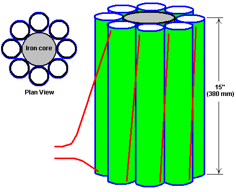 The generator was initially demonstrated powering an 18-foot boat with a 35 horsepower electric motor, around Portage Bay on Lake Union, Seattle at eight to ten knots, starting from the Seattle Yacht Club wharf. It appears that the wires should have been larger diameter as they started to overheat quite quickly. Dozens of people witnessed this demonstration and it was reported in the local Seattle press. Alfred is reported to have referred to the secondary windings as “electromagnets” each having both primary and secondary windings of copper wire. Details of the device are presented in Joseph Cater’s book “Awesome Force” which attempts to explain the theory of its operation. The circuit looks deceptively simple, with the DC input being converted to a rapid train of very short duration pulses, stepped up in voltage and fed to the primary winding. The output is passed through a step-down transformer and was said to be 280 Amps at 125 Volts: 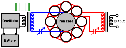 The variable capacitors shown are used to tune the input and output circuits to their resonant frequencies. There appears to be similarities between this circuit and the circuitry used by Edwin Gray when he was using his power tube to drive mains light bulbs and other standard electrical equipment. Edwin used air-cored transformer windings of very heavy-duty wire, to drive the loads and while Alfred does have steel formers for the secondary coils, they are mainly air-core, unlike his primary coil. Edwin and Nikola Tesla were tapping the same source of power, and since Alfred Hubbard worked with Tesla for a short period, it seems likely that his transformer is based on the same techniques that Tesla used so successfully. It may well be that Alfred’s circuitry was actually constructed more like Tesla’s circuitry for his unique coils. It might have been like this: 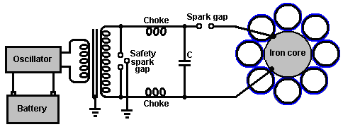 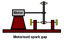 Alfred’s association with Tesla raises some interesting points. Firstly, Tesla was aware that to generate Radiant Energy waves of the type that Edwin Gray trapped so successfully, ideally, uni-directional pulses of very short duration (1 millisecond or less) were needed. The best way to generate these is using a spark, so it is distinctly possible that Alfred’s oscillator contained a spark generator. Secondly, Tesla was aware that a serially-connected bi-filar wound coil is a very effective device for collecting Radiant Energy. Might it be possible that the information on how the secondary coils were wound and connected is not quite correct, and that while the coils were connected in series, they were bifilar-wound? In fact, it seems much more likely that there were separate inner bi-filar windings connected in series while the outer bi-filar windings were also connected in series, especially since, it was reported that the device had four wires coming out of it. This strongly suggests that the bi-filar series-connected ‘secondary’ windings were connected internally to form the final circuit and that the four wires were one pair for the primary winding and one pair for the serially-connected pickup set of sixteen windings: 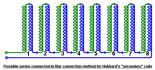 The device was examined and tested fully by Father William Smith, professor of physics at Seattle College. He was quoted as saying “I unhesitatingly say that Hubbard’s invention is destined to take the place of existing power generators”. While this indicates that Professor Smith’s examination and tests showed that the device worked extremely well, he clearly was not aware of the marketplace opposition to any commercial form of free-energy device. It has been suggested that the core of the device was packed with radio-active material (probably radium) and that an outer steel cylinder was placed around the device to absorb excess radiation. If that was so, the amount of material would have been very minor, and used only to ionise the air around the coils to improve the energy pick up. Any radio-active material used would have been similar to the ‘luminous’ paint which used to be applied to the hands of alarm clocks, and consequently, fairly harmless. What appears to be an implementation of the Hubbard coil system, or perhaps a very closely related device is Joseph H. Cater’s self-sustaining electrical generator. As usual, information on it is limited and not particularly clear, so the following is just my attempt to piece together some information from different sources. Much of this information comes from a document which has Geoff Egel’s name on it and although it seems likely that Geoff is quoting some other source, my thanks goes to him for sharing what we have here. The diagrams give the names of various minor websites none of which exist any longer and so these have been removed as they have no useful purpose any longer. Here is an original diagram from this information:  As it seems to me that there are many conflicting details in this information, I am presenting it here in pretty much the same form in which it reached me: Mr. Cater claims that a group in California built this device which, it is claimed, performed very well, but he does not claim that he has personally seen or tested such a device. This design is published for researchers and experimenters in order that a working prototype may be developed. Mr. Cater says "I would be willing to give big odds that if my instructions are carried out to the letter, then sensational results will be obtained. It should easily outperform any other generator that has ever been built including the Moray and the Hubbard devices. It could easily be mass-produced. Some years ago I got word from someone in Germany who built a similar configuration (a very poor replica of this one, where the output coil consisted of only windings on a solid iron bar which in turn was surrounded by smaller coils on smaller bars which constituted the input. Even this was quite successful as the output was three times the input. I do not know what happened to the builder but such a crude device as this could give the world free energy. The output of a small unit could be used as the input for a larger one and so on.” Please bear in mind that these plans are not meant to be explicit in every fine detail, but are provided as the best guide that the author can make with the available data. Therefore you will need to use some of your own ingenuity and design skills in the construction of this rather unusual coil configuration. The Primary Coil Input-driver: Suggestions for the Bench-test Prototype I would suggest the construction of an input power supply which can vary Frequency, Voltage and Current. A frequency range of 50 Hz to 1,000 Hz would be a good starting point. The higher the frequency of the input current (the amperage and voltage being held constant) the greater the induced output E.M.F. as it is directly proportional to the frequency (the rate of change of the magnetic flux). A frequency of 50 or 60 Hz would be more convenient to experiment with as these frequencies are standard power mains frequencies, however a frequency of 360 Hz or higher is recommended. Mr. Cater suggests that for experimental purposes in determining the input needed to get the desired output, that rectified 12 volt AC is used. Sinusoidal waves should be used and not square waves. Because of its tremendous potential, care should be taken to limit the amount of input current. One should start with a low frequency (50 or 60 Hz) and low amperage, then gradually increasing the current until the desired input / output is obtained. Such caution was not followed with a previous model built by a group in California and it resulted in the disintegration of the output coil. The iron sheets in this model were not plated and did not have the caps fitted. Nevertheless, it was still an effective orgone accumulator. The gold plating of the iron sheets and the addition of the CAPS enables it to operate with a much lower input current and lower frequency. The Primary Coils If the outer body of your secondary coil is eight inches in diameter, then you won’t fit the recommended seventeen primary coils around its perimeter. If your primary coils are one and a half inches in diameter then these will fit nicely around the perimeter of an 8-inch diameter secondary coil. However, it is preferable to have larger primary coils as mentioned in Mr Cater’s opening comments, so it may be advisable to stick to the recommended 2-inch diameter size for the primary coils, but settle for one less and use only 16 primary coils. Experimentation will decide which is the best way to go. For the purposes of this article I will refer to 2-inch diameter coils. Cut medium gauge soft iron rods (oxy-welding rods will do) to 13-inch lengths. Be sure to de-burr the cut rods so that a compact fit is achieved. Next, wind each coil separately with one terminal at each end (no gap ‘G’ is required for the primary coils). Then the primary coils are physically mounted around the large secondary coil - refer to Diagram 1.  The primary coils are then interconnected with suitable leads of the same gauge as the coil wire to form a series coil configuration. Refer to Diagram 2.  All coils must be wound in an identical manner so that the current in each one travels in a clockwise or counter clockwise direction. It is essential that the current flows in the same direction. The Secondary Coil: Construction Notes The secondary coil consists of a number of concentric cylinders and coils of three varying types repeated in a special sequence as detailed here.
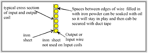 The gap ‘G’ reduces the inertia of flowing electrons as well as providing room for the oil-soaked iron powder which is to be packed between each winding. Perhaps 1 mm to 1.5 mm would be a sufficient gap between adjacent turns of the winding. However, before packing each coil with the iron powder, it would be advisable to lacquer the coil winding to seal it in position on the iron sheeting. This also provides extra insulative protection. The purpose of the non-metallic concentric spacers within the secondary coil serves two purposes: a. To minimise the cancellation effects. b. To produce an Orgone accumulator effect. The material used could be heavy-duty PVC tubing with quarter-inch thick walls or quarter-inch thick sheeting, possibly heat treated, wrapped around the coils. You may be lucky for one or two of the concentric rings required, and have a piece of PVC tubing which is just the right diameter. For the remaining diameters you could reduce the circumference of a larger piece of tubing, thus converting it to the desired diameter. Be sure that the butt joint is perfect or that any gaps in the join are filled in with a suitable plastic filler. Some innovation and ingenuity may be required for this part of the construction. The general strategy for building this multi-layered secondary coil is to build it by winding each coil on separate concentric cylinders consisting of the gold-plated iron sheeting wrapped around the non-metallic spacer. The inner diameter of one cylinder will be the outer diameter of another. They are then joined together one inside the other. Fly wires are then used to interconnect the ends of each coil. For initial experiments this may be done in several ways, two of which are recommended by Mr. Cater:
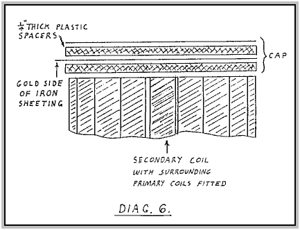 The leads should take the shortest path around the outer face of the secondary coil and of course they should be of the same gauge as the actual coil winding itself. Refer to Diagram 4 The Side Caps Now that you have completed the secondary coil and wound the primary coils, the next step is to cut the caps to their correct size so that their diameter will be big enough to cover in the entire primary and secondary coil assembly. Refer to Diagram 1 above where the required dimension is marked as "Dia. C”
Devise a method to attach the caps to the sides of the unit and a means of positioning the outer primary coils so that they are all held in their correct positions. Bear in mind that powerful magnetic forces will be present and that the unit itself will be quite heavy, so a strong form construction is needed. One suggestion is to use dowels to hold the caps in position and use suitably shaped plastic spacers to position and hold the primary coils in place. Once the caps have been fitted, the generator becomes a highly potent orgone accumulator. 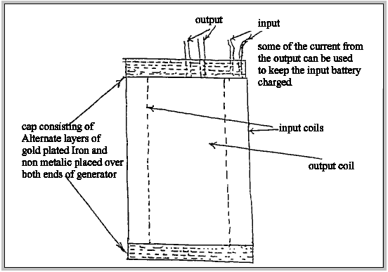 Gold-plated iron is many, many times more effective than any other metallic material. The accumulator effect greatly increases the effectiveness of the generator. Testing Now that you have actually completed all the construction work, you now need a suitable input driver unit which should have been thoroughly tested and ready for driving the unit. Let’s be optimistic and hook up a good size load for the secondary, a couple of radiator bars (electric heaters) should do to begin with. Across the output terminals you can connect all the usual test gear. Summary The construction of the secondary coils may be carried out by completing the following steps:
Another source comments on the Cater device as follows: A self-sustaining electric generator was demonstrated at Seattle, Washington in 1919 by an inventor named Hubbard. His invention was supposedly 14 inches long and 11 inches in diameter. It powered a 35 horsepower electric motor which pushed a boat continuously around the bay for several hours. This demonstration was witnessed by thousands. During the time of his demonstrations, Hubbard made a sketch of one of his smaller generators used to power ordinary electrical appliances shown in Fig. 28: 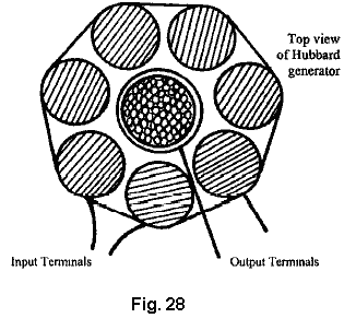 It was approximately six inches long and about five inches in diameter. It consisted of eight coils in series, wound on iron cores which in turn surrounded a slightly larger central coil. The central coil was wound on a hollow tube which contained many small rods of soft iron. Four terminals extended from the unit, two connecting to the outer coils which received the input current, while the other two came from the central coil. It is highly significant that both wires used in the generator appeared to be of heavy gauge like those used in power lines with the same kind of insulation. Each coil had only one layer of this wire which means that only a moderate number of turns were used in the entire generator. It is known that the generator produced a fluctuating current of an undisclosed frequency and had no moving parts. The basic principle on which the generator operated is apparent. A small current passed through a coil with a moderate number of turns per unit length will magnetise an iron core to a surprising degree. This principle is utilised to great advantage in electromagnets. What apparently hasn’t been realised is that during the brief interval in which the current builds up after it is turned on, an induced EMF (voltage) is produced in the coil by the changing magnetic flux, which is in the same direction as the current. This induced EMF is the result of the magnetic field produced by the magnetisation of the iron core. If this induced EMF were in the opposite direction to the current, then a sizeable current could never be produced in the coil as the EMF opposing the current would automatically cancel it before it could increase. 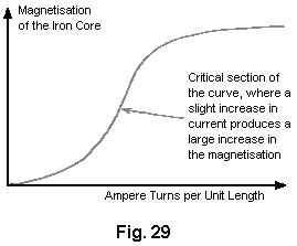 Fig. 29 shows a graph of the magnetisation of an iron core plotted against ampere turns per unit length. The term “ampere turns” is the number of turns of the coil per unit length multiplied by the number of amps of current flowing through the coil. For example, a current of 1 amp flowing through a coil of 100 turns will produce the same effect as 2 amps flowing through a coil of the same length which has only 50 turns. There is a section on the curve where a slight increase in ampere turns will produce a tremendous in magnetisation of the iron core. The cause of this phenomenon should be analysed. It seems strange that just a few ampere-turns can produce extensive and significant magnetisation of the iron core. Yet, the observable magnetic field produced by the current without the magnetic core is tiny by comparison. A similar field produced by a permanent magnet, would be unable to induce a noticeable magnetisation of the iron. This is something which conventional science has found convenient to ignore. If an alternating current is passed through an electromagnet and the ampere-turns exceed a critical point, a chain reaction takes place in the coil, producing a tremendous increase of current in the coil. This is responsible for transformers which occasionally burn out during current surges. In some cases the sudden increase in current is sufficient to push the ampere-turns value into this critical range. The chain reaction results from an increase in the magnetisation of the iron which produces an increase in the current, which then produces an additional large increase in magnetisation, and so on until the iron reaches its maximum degree of magnetisation. This process occurs during the first half of the AC cycle. The EMF is flowing in the direction opposite to that of the current after it reaches its maximum value and the second part of the cycle begins. This EMF, which is the same magnitude as that which brought the current to its maximum value during the first part of the cycle, now acts as a brake and stops the current. The applied alternating EMF then starts the current in the opposite direction and the identical process occurs again with the current flowing in the opposite direction. Normal working transformers have ampere-turns which are well below this critical point. The additional EMF induced in the coils by the magnetisation of the iron offsets the natural inductive impedance of the coils. This is why transformers have such a high degree of efficiency. If any material other than iron or special steel were used for the core, the efficiency would drop significantly. A normal square-wave pulsed current cannot be used in such a device due to the very short time of the rise and fall of the applied voltage, so a sine wave power supply is needed to produce this effect. Since the induced EMF in a coil is directly proportional to the rate of change of magnetic flux, it follows that the higher the frequency of this sine wave supply, the better. There is possibly another factor which could contribute to the success of the Hubbard device. At that time, the only insulated wire available had thick and heavy insulation. This means that adjacent turns of wire in the coil were separated by a distance equal to twice the thickness of the insulation. Consequently, the gap resulted in a cancellation of magnetic effects produced by electrons flowing in the wire. Since inertia is dependent on the ability to generate a magnetic field, the inertial properties of the electrons would be almost nullified. There is an optimum distance between the wires which would produce the maximum effect. It seems likely that the thick insulation on Hubbard’s wire produced this optimum distance. Most of the resultant magnetic field was that which encircled both wires and that would be the weaker part of the field. This means that a relatively low EMF could accelerate a larger number of electrons to a high velocity during a very short period of time. As the electrons leave the coil, inertia returns. This would result in a backup of a high concentration of electrons in the coil. Since electrostatic repulsion is not affected, electrons would be ejected from the coil at a high velocity despite their increased inertia. This would produce an output of both high voltage and high amperage. Floyd Sweet’s VTA. Another device in this category of pulsed devices which tap external energy was produced by Floyd (“Sparky”) Sweet. The device was dubbed “Vacuum Triode Amplifier” or “VTA” by Tom Bearden and the name has stuck, although it does not appear to be a particularly accurate description. There is very little practical information available on this device, though there is a video of it in operation on the web.  The device was capable of producing more than 1 kW of output power at 120 Volts, 60 Hz and is self-powered. The output is energy which resembles electricity in that it powers motors, lamps, etc. but as the power increases through any load there is a temperature drop instead of the expected temperature rise. When it became known that he had produced the device he became the target of serious threats, some of which were delivered face-to-face in broad daylight. It is quite possible that the concern was due to the device tapping zero-point energy, which when done at high currents opens a whole new can of worms. One of the observed characteristics of the device was that when the current was increased, the measured weight of the apparatus reduced by about a pound. While this is hardly new, it suggests that space/time was being warped. The German scientists at the end of WWII had been experimenting with this (and killing off the unfortunate people who were used to test the system) - if you have considerable perseverance, you can read up on this in Nick Cook’s inexpensive book “The Hunt for Zero-Point” ISBN 0099414988. Floyd found that the weight of his device reduced in proportion to the amount of energy being produced. But he found that if the load was increased enough, a point was suddenly reached where a loud sound like a whirlwind was produced, although there was no movement of the air. The sound was heard by his wife Rose who was in another room of their apartment and by others outside the apartment. Floyd did not increase the load further (which is just as well as he would probably have received a fatal dose of radiation if he had) and did not repeat the test. In my opinion, this is a potentially dangerous device. It should be noted that a highly lethal 20,000 Volts is used to ‘condition’ the magnets and the principles of operation are not understood at this time. Also, there is insufficient information to hand to provide realistic advice on practical construction details. On one occasion, Floyd accidentally short-circuited the output wires. There was a bright flash and the wires became covered with frost. It was noted that when the output load was over 1 kW, the magnets and coils powering the device became colder, reaching a temperature of 20 degrees Fahrenheit below room temperature. On one occasion, Floyd received a shock from the apparatus with the current flowing between the thumb and the small finger of one hand. The result was an injury akin to frostbite, causing him considerable pain for at least two weeks. Observed characteristics of the device include: 1. The output voltage does not change when the output power is increased from 100W to 1 kW. 2. The device needs a continuous load of at least 25W. 3. The output falls in the early hours of the morning but recovers later on without any intervention. 4. A local earthquake can stop the device operating. 5. The device can be started in self-powered mode by briefly applying 9 Volts to the drive coils. 6. The device can be stopped by momentary interruption of the power to the power coils. 7. Conventional instruments operate normally up to an output of 1 kW but stop working above that output level, with their readings showing zero or some other spurious reading. It appears that Floyd’s device was comprised of one or two large ferrite permanent magnets (grade 8, size 150 mm x 100 mm x 25 mm) with coils wound in three planes mutually at right angles to each other (i.e. in the x, y and z axes). The magnetisation of the ferrite magnets is modified by suddenly applying 20,000 Volts from a bank of capacitors (510 Joules) or more to plates on each side of it while simultaneously driving a 1 Amp 60 Hz (or 50 Hz) alternating current through the energising coil. The alternating current should be at the frequency required for the output. The voltage pulse to the plates should be applied at the instant when the ‘A’ coil voltage reaches a peak. This needs to be initiated electronically. It is said that the powering of the plates causes the magnetic material to resonate for a period of about fifteen minutes, and that the applied voltage in the energising coil modifies the positioning of the newly formed poles of the magnet so that it will in future, resonate at that frequency and voltage. It is important that the voltage applied to the energising coil in this ‘conditioning’ process be a perfect sinewave. Shock, or outside influence can destroy the ‘conditioning’ but it can be reinstated by repeating the conditioning process. It should be noted that the conditioning process may not be successful at the first attempt but repeating the process on the same magnet is usually successful. Once conditioning is completed, the capacitors are no longer needed. The device then only needs a few milliwatts of 60 Hz applied to the input coil to give up to 1.5 kW at 60 Hz at the output coil. The output coil can then supply the input coil indefinitely. The conditioning process modifies the magnetisation of the ferrite slab. Before the process the North pole is on one face of the magnet and the South pole on the opposite face. After conditioning, the South pole does not stop at the mid point but extends to the outer edges of the North pole face, extending inwards from the edge by about 6 mm. Also, there is a magnetic ‘bubble’ created in the middle of the North pole face and the position of this ‘bubble’ moves when another magnet is brought near it. The conditioned slab has three coil windings: 1. The ‘A’ coil is wound first around the outer perimeter, each turn being 150 + 100 + 150 + 100 = 500 mm long (plus a small amount caused by the thickness of the coil former material). It has about 600 turns of 28 AWG (0.3 mm) wire. 2. The ‘B’ coil is wound across the 100 mm faces, so one turn is about 100 + 25 + 100 + 25 = 250 mm (plus a small amount for the former thickness and clearing coil ‘A’). It has between 200 and 500 turns of 20 AWG (1 mm) wire. 3. The ‘C’ coil is wound along the 150 mm face, so one turn is 150 + 25 + 150 + 25 = 350 mm (plus the former thickness, plus clearance for coil ‘A’ and coil ‘B’). It has between 200 and 500 turns of 20 AWG (1 mm) wire and should match the resistance of coil ‘B’ as closely as possible. Coil ‘A’ is the input coil. Coil ‘B’ is the output coil. Coil ‘C’ is used for the conditioning and for the production of gravitational effects.  At time of writing, information and photographs of the original device can be found on this website where a paper by Michael Watson gives much practical information. For example, he states that an experimental set up which he made, had: The ‘A’ coil with a resistance of 70 ohms and an inductance of 63 mH, The ‘B’ coil, wound with 23 AWG wire with a resistance of 4.95 ohms and an inductance of 1.735 mH, and The ‘C’ coil, also wound with 23 AWG wire, with a resistance of 5.05 ohms and an inductance of 1.78 mH. Collapsing Field Technology. At the website http://community-2.webtv.net/hotmail.com/prime137/ConvertingOffShelf/ the following, very interesting presentation is made: CFT- (Collapsing Field Technology) - Updated 2008 In electrical systems, the term "back emf" actually refers to the equal and opposite force field accompanying the "forward emf", in any "symmetrical" electrical system. In magnetic systems, the corresponding term is "forward and back magnetic motive force", rather than "forward and back electric motive force". All rotating motors actually turn themselves from the broken symmetry which is created inside them. The present day engineers have been taught that they must pay to put extra energy into the system, just to break its symmetry. That of course is totally false. Otherwise, a rotating electron (with its continual spin) would not spin. In a normal motor, we are taught to put in a coil (say, there in the back mmf region) and then we pay to put in a sudden surge of electromagnetic energy into that coil, so that it momentarily overrides (cancels) the back mmf force. In short, we momentarily make the system asymmetrical, so that its net back mmf is less than its forward mmf. That means that now the motor retains at least some of its excess acceleration and excess angular momentum added to the flywheel and shaft in its previous acceleration (forward mmf) zone, but we are "paying" (the electric power grid) to have this occur. Anyway, once that broken symmetry between forward and back mmfs is there, with the back mmf deliberately reduced so that it is less than the forward mmf, the motor will self-rotate because of its own system asymmetry. For more than one hundred years this effect has been viewed as a problem to be designed out of electrical systems, perhaps because of greed. No one had seriously considered it as a source of abundant free energy. Everyone knew it was there, but no one recognised it’s potential. Standard electrical generator systems can be modified inexpensively to the Over-Unity / Asymmetrical design concept by the addition of a second set of commutator brushes and/or the addition of a second slip ring assembly. Present day electrical generators can be converted to Over-Unity output, as asymmetrical rotation can be achieved in just a few hours of adaptation work. The additional commutator and slip ring collect, or scavenge, the collapsing electromagnetic fields (C.E.M.F.) of both the armatures and field coils of standard electrical generator sets. Present day electrical generator design throws away the tremendous amount of electrical energy stored in these collapsing fields. You pay for it, so why not get the benefit from it? Everyone who makes use of electrical circuits has always considered the collapsing field effect to be a nuisance because, when using a mechanical relay coil in an electronic circuit, it would cause a current to be pumped back into the circuit, creating havoc. One solution to the problem of C.E.M.F. was to install a diode across the coil leads so that when the power was removed, the C.E.M.F. caused a current flow which passed through the diode and which was dissipated as heat in the coil itself, rather than in the circuit. So, to effect this modification, on the armature / exciter element just install a second set of brushes or slip rings, the exact amount behind the driver units which is needed to collect the C.E.M.F. of the armature field collapse, and take it out of the system to be used as an additional generated electrical supply. The additional new C.E.M.F. outputs can easily be phased to the original output system load wiring. These modifications more than double the generator’s output power for just a small modification cost / time, and no increase in operating costs. This general design modification allows almost any currently manufactured electrical generator to be an over-unity design, and with some additional external modifications a self-powered over-unity configuration can be obtained on most commercial electric generators by any competent electrical engineer. Why pay for fuel / power that you have available in your generator system already? Again, just collect the C.E.M.F. of the armature and field coil’s collapses for far-over unity operation of these devices, and with external circuit additions, stand-alone, fuel-less electrical power is available to everyone, in the form of an off-the-shelf, self-sustaining, asymmetrical, electrical generator. The same modifications can be made in most manufactured motors as they can easily be converted into generators. Just scavenge the collapses of the armature and field coil, control it with an external circuit, and you have a stand-alone over-unity electrical generator. There is a stationary "motionless electromagnetic generator” design, based on the Alexander patent that has been built experimentally. No far out zero-point vacuum explanations are needed to explain its operation. The best form of any such generator would have no moving parts. Looking at any common transformer, and considering how it works, supplies the answer. In any kind of transformer, electricity is transferred between the two coils by the magnetic field. When a coil is initially powered up or switched off, that coil creates a magnetic field which causes a rush of electricity, usually called a 'voltage spike'. In conventional electronics, this voltage spike is suppressed to protect the other circuit components from damage. In collapsing field technology (CFT), that voltage spike is harnessed, rather than being suppressed. If I take a DC signal generator power supply, and connect it to the primary of the transformer, I can make a generator of sorts. I'll turn on the DC signal in the primary coil windings for just an instant, and then turn it off. In the secondary there is a flux linkage which mirrors the primary signal and this is some 90% of the input power. But we can recover this field collapse in the secondary' and gain an additional 90% of the input power. Thus, any transformer secondary can produce a total output power which is about 180% of the input power in this mode, with a DC input signal which is a gradually applied quarter-sine or saw tooth wave shape. But wait, we are throwing recoverable power away when the primary coil winding's field collapses. By applying the DC power input signal and then, when the input power is cut off, switch the primary winding's field collapse to the output also, the primary field collapse contributes at least another 90% to the output, for a grand total output power of about 270% of the input power, with this design. The DC power signal must only power the primary winding up and then let disconnect at the peak voltage. This allows the primary winding to be switched to the output to recover the power in its field collapse, which is in synchronisation with the field collapse in the secondary winding. Simple electronic switching can accomplish all of these functions, at little power usage and low cost. Therefore, the gain of a transformer over-unity generator would probably be about 250% output power to input power, and no mechanical movement is needed. Many old motors and generators could be adapted to this transformer design. The armature must be held so that it is permanently stationary and the air gap between armature and field coils filled with iron filings. The air gap iron filings, or iron powder filling is to make the best use of the primary's (armature) full magnetic flux power. This produces the best transformer action and the highest power gain possible with this conversion design. Cooling, through holes, can be left in the air gap if necessary in these units. The external switching electronic circuitry is the same as for the standard transformer design, described above. All we have done is to turn the motor / generator into a reasonable transformer. What is happening in this design is that for one "up" drive voltage pulse (power signal) in the primary coil, we get the "up" (field build) in the secondary coil and the "downs" (field collapses) of both the secondary and primary coils, as output power. Think of the primary coils as coupled "springs" and it will all be clear. This transformer / generator design has been the nature of electromagnetic coils all the time - we just never saw it. If the unit is actuated 60 times a second, allowing for the counter-electromotive force field collapses, it makes a standard household 60 Hz electrical power generator. This design concept is the natural last step after recovery of secondary collapses was introduced in generator designs. The same gain principle and results could then be achieved in capacitor systems. The charge (up) cycle from the secondary plate and the two discharge cycles from both the secondary and primary plates would be the output power. The basic external switching electronics is generally the same as in the transformer designs. These designs are in the basic nature of energy storage / transfer elements - one input power pulse produces one input transfer plus two storage collapses or discharges as output power, which is a gain of about 300%. Rosemary Ainslie. Rosemary Ainslie has produced a pulsed heater system which has been measured at a performance of COP = 17. This is a recent design and as far as I am aware, has not yet been replicated by other people. Panacea-bocaf.org are working with Rosemary's original developers to produce an independent implementation of the heater. At this point in time, the heater has been built to a prototype testing scale for laboratory examination and measurement and not been produced in the kilowatt range, which, hopefully, will come at a later date. Panacea have produced a 250-page document describing the research, the testing, the theory, etc. and that can be downloaded free using this link. As that document contains the details which scientists need to see for serious testing and development, it may be a little technical for some people, so Panacea have produced a simplified version aimed at the average home-build investigator and that can be downloaded free using this link. In very broad outline, the circuit produces the same very short, very sharp voltage pulses that are the basis for so many "free-energy" devices. The circuit used looks very simple but in spite of that, the way that it operates is not at all simple. The circuit is shown below and to a quick glance, it looks like a standard 555 timer chip circuit, used in many existing applications. However, if the circuit is operated as a 555 pulsing circuit, then the output is not COP>1. Looking more closely, we notice that the link between the output of the 555 chip on pin 3 and the input gate pin of the Field-Effect Transistor, is unusual as it is not the usual voltage divider between pin 3 and the 0-volts ground line. Instead, the gate is directly coupled to the 555 chip output by a single, low-resistance preset resistor. Normally, an NE555 chip struggles to reach 50,000 cycles per second and a large number of 555 chips on the market can't even operate at even that frequency. To get Rosemary's circuit into it's COP>1 operation, the resistor marked "GATE" is adjusted very slowly to find the point at which the circuit becomes unstable, over-rides the normal operation of the 555 chip and starts oscillating at the resonant frequency of the overall circuit, forcing the 555 chip to become a feedback component. The circuit then produces the sharp, short voltages spikes at more than ten times the operating speed of the 555 chip and pulsing the 10-ohm heating element marked "LOAD" at about 500,000 pulses per second. That rate of operation is clearly well outside the possible performance of an NE555 chip, besides which, the timing elements of the chip should be producing a much lower frequency, as indeed it does before the "GATE" resistor adjustment causes the circuit to break out of its normal design-mode operation and start the high-speed spike generating, resonant performance. The circuit used is shown here: 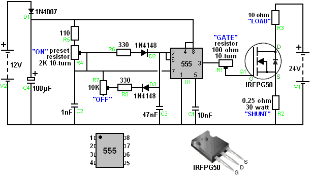 As Panacea-bocaf are working to test and develop this circuit further, it would be a good idea to download their free documentation on the design and keep an eye on their progress in this field. The two documents give very considerable detail on the work which has already been done, and of course, you can yourself, experiment with this circuit and see what results and adjustments you can discover yourself. Patrick Kelly engpjk@yahoo.co.uk http://www.free-energy-info.co.uk/ |