It is generally not realised that
excess energy can be obtained from pulsing a flywheel or other
gravitational device.  This fact has recently been stressed by Lawrence Tseung who refers to the extra energy obtained in this way as being “Lead-out” energy. This gravitational feature has been part of university Engineering courses for decades, where it has been taught that the loading stress on a bridge caused by a load rolling across the bridge is far less than the stress caused if that same load were suddenly dropped on to the bridge. This impulse technology has been known for some time and it is demonstrated driving a canoe in the video at this location but Lawrence points out the potential for using it as a method for gaining excess energy for practical use. In October 2009, Lawrence and his band of helpers ran public demonstrations of an early prototype electrical pulsing system which produces excess output energy of COP = 3.3, that is, with 3.3 times more output energy than the user has to put into it to make it work: 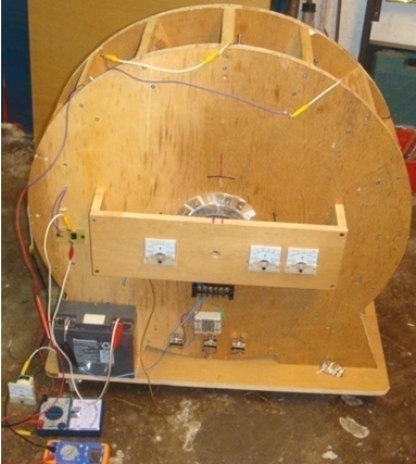 Lawrence is busy developing this device further as he intends to construct one with a output energy excess of several kilowatts. Behind this device is Lawrence's "Lead-out" theory and for this he suggests a simple arrangement to demonstrate the principle. He presents the case of a rotor which has two substantial weights contained in two cylinders attached to the rotor:  As the disc rotates, the ball falls down the length of the tube. At one end, the tube has a rigid cap which causes a significant impact when the ball hits it. The other end of the tube is padded and that cushions the impact which causes a net imbalance in the impacts and that maintains the rotation. There is a prototype implementation on YouTube but the implementation is not adequate and the disc stops rotating after five minutes. The YouTube video slot is located here and there are two significant problems with that particular build. Firstly, the tube rotation is too slow to be effective and instead of the weight falling under gravity and acelerating to a good speed before the impact, the weight just rolls gently down a minor slope and does not make a major impact. Secondly, the weights are far too small for the size of the wheel and there are only two weights providing impacts very widely spaced apart as the wheel rotates only slowly. One man made a ten-foot version and it rotated steadily for ten months after which time his wife insisted that it be taken apart as it was too noisy. I would suggest some modifications to the wheel as Lawrence is far too busy with developing his COP>1 pulse implementation. Firstly, the movement of each weight should be delayed until the tube is much nearer the vertical. This can be achieved by curving part of the tube like this:  This way, the ball does not start rolling until the main part of the tube is near vertical. This allows a much greater acceleration and impact. The weighted ball should be much larger, say 2" (50 mm) in diameter and made of lead, in order to generate a significant thrust. Also, the cushioned ends of the tubes should be aligned with the pivot of the wheel so that any residual impact does not generate a turning force in the wrong direction. there is a negative turning effect due to the lever arm of the bottom weight. This turning force is only there for a small arc of rotation as the weight will roll inwards as soon as the tube section rises above the horizontal and as the tube then transitions into a circular curve, the movement inwards is gentle. It probably would be better if the tubes were angled slightly more in the clockwise direction, rather than exactly as shown in the diagram. Secondly, there should be eight tubes on the disc, four on each side and one side staggered by 45 degrees so that there is a driving impact every 45 degrees instead of the 180 degrees of the version shown in the YouTube video. With that arrangement of four times as many impacts, each substantially greater, and no significant reverse impacts, the wheel has a much better chance of successful rotation without needing to be particularly large. The wheel itself should not be light as it acts as a flywheel and a pulsed flywheel has already been shown to produce excess power. The wheel bearings should be ball races and not the closed variety because those ones are packed with grease and have a serious resistance to rotation. Instead, the open-sided variety of ball bearing should be used as they rotate very freely.  The Chas Campbell System. Recently, Mr. Chas Campbell of Australia demonstrated electrical power gain with a flywheel system which he developed:  But what this diagram does not show, is that a couple of the drive belts are left with excessive slack. This causes a rapid series of jerks in the drive between the mains motor and the flywheel. These occur so rapidly that they do not appear noticeable when looking at the system operating. However, this stream of very short pulses in the drive chain, generates a considerable amount of excess energy drawn from the gravitational field. Chas has now confirmed the excess energy by getting the flywheel up to speed and then switching the drive motor input to the output generator. The result is a self-powered system capable of running extra loads. Let me explain the overall system. A mains motor of 750 watt capacity (1 horsepower) is used to drive a series of belts and pulleys which form a gear-train which produces over twice the rotational speed at the shaft of an electrical generator. The intriguing thing about this system is that greater electrical power can be drawn from the output generator than appears to be drawn from the input drive to the motor. How can that be? Well, Mr Tseung’s gravity theory explains that if a energy pulse is applied to a flywheel, then during the instant of that pulse, excess energy equal to 2mgr is fed into the flywheel, where “m” is the mass (weight) of the flywheel, “g” is the gravitational constant and “r” is the radius of the centre of mass of the flywheel, that is, the distance from the axle to the point at which the weight of the wheel appears to act. If all of the flywheel weight is at the rim of the wheel, the “r” would be the radius of the wheel itself. This means that if the flywheel (which is red in the following photographs) is driven smoothly at constant speed, then there is no energy gain. However, if the drive is not smooth, then excess energy is drawn from the gravitational field. That energy increases as the diameter of the flywheel increases. It also increases as the weight of the flywheel increases. It also increases if the flywheel weight is concentrated as far out towards the rim of the flywheel as is possible. It also increases, the faster the impulses are applied to the system. Now take a look at the construction which Chas has used:  You notice that not only does he have a heavy flywheel of a fair size, but that there are three or four other large diameter discs mounted where they also rotate at the intermediate speeds of rotation. While these discs may well not have been placed there as flywheels, nevertheless, they do act as flywheels, and each one of them will be contributing to the free-energy gain of the system as a whole. If the drive motor were a DC motor which is deliberately pulsed by a special power supply, then the effect is likely to be even greater. It is not clear if the irregular drive which makes this system work so well is due to the way that the mains motor works, or to slight slippage in the drive belts. The bottom line is that Chas’ system produces excess energy, and although it is by no means obvious to everybody, that excess energy is being drawn from gravity. Ok, so what are the requirements for an effective system? Firstly, there needs to be a suitable flywheel with as large a diameter as is practical, say 4 feet or 1.2 metres. The vast majority of the weight needs to be close to the rim. The construction needs to be robust and secure as ideally, the rate of rotation will be high, and of course, the wheel needs to be exactly at right angles to the axle on which it rotates and exactly centred on the axle:  Next, you need a motor drive which gives a rapid pulsed drive to the shaft. This could be one of many different types. For example, the original motor design of Ben Teal where very simple mechanical contacts power simple solenoids which operate a conventional crankshaft with normal connecting rods:  This style of motor is simple to construct and yet very powerful. It also meets the requirement for rapidly repeated impulses to the axle of the flywheel. The motor power can be increased to any level necessary by stacking additional solenoid layers along the length of the crankshaft:  This style of motor looks very simple and its operation is indeed very simple, but it is surprising how powerful the resulting drive is, and it is a very definite contender for a serious free gravitic energy device in spite of its simplicity. An alternative suitable drive system could be produced by using the same style of permanent magnet and electromagnet drive utilised by the Adams motor, where electromagnets positioned just clear of the edge of the rotor disc are pulsed to provide an impulse to the drive shaft, in the case shown below, every 30 degrees of shaft rotation.  Here, the sensor generates a signal every time that one of the permanent magnets embedded in the rotor passes it. The control box circuitry allows adjustment of the time between the arrival of the sensor signal and the generation of a powerful drive pulse to the electromagnets, pushing the rotor onwards in its rotation. The control box can also provide control over the duration of the pulse as well, so that the operation can be fully controlled and tuned for optimum operation. Any ordinary DC motor driven by a low-rate DC motor “speed controller” would also work in this situation, as it will generate a stream of impulses which are transmitted to the flywheel. The shaft of the flywheel will, of course, be coupled to an automotive alternator for generation of a low voltage output, or alternatively a mains voltage generator. It should be stressed that having several flywheels as part of the drive gearing, as Chas Campbell does, is a particularly efficient way of leading-out excess gravitational energy. Part of the electrical output can be used to provide a stabilised power supply to operate the drive for the flywheel. It is possible to make the Chas Campbell arrangement into a more compact construction by reducing the size of the flywheel and introducing more than one flywheel into the design. It is perfectly possible to have more than one flywheel on a single axle shaft. The construction of the flywheels can be efficient if a central steel disc is used and two cast lead collars are attached to the rim on both sides of the web disc. This produces a flywheel which is as cheap and effective as can conveniently be made. Although it is not shown on the diagram shown above, Chas does use additional discs. These are not particularly heavy, but they will have some flywheel effect. Ideally, these discs should be beefed up and given considerable weight so that they contribute substantially to the overall power gain of the device. This is what Chas’ present build looks like:  A possible alternative construction might be:  Here, there are five heavy flywheels mounted on two heavily supported strong axles, and while the two shown in dark green are only rotating at half the speed of the other three, the energy gain will be equal for each flywheel as each receives the same train of drive pulses. The drive impulses can be from a DC motor fed with electrical pulses, perhaps via a standard “DC motor speed controller” or using electrical pulses to drive a series of permanent magnets spaced out around the edge of a circular rotor. In this instance, the electrical generation can be via a standard commercial generator, or it can be produced by using the electromagnet driving coils alternately to drive and to capture electrical energy. The following sketch shows a possible arrangement for this concept:  Ted Ewert. Ted has come up with a very clever, cheap and simple method of getting a pulsed flywheel. He has taken a standard DC electric motor and modified it very simply. He opened the motor up and found that it has 28 coils and two brushes. He then cut the connections to two adjacent coils. As there are two brushes, that produces two pulses per rotation. He then selected the two coils directly opposite his cut connections and cut two more side by side there. This gives four pulses per revolution. The arrangement is now, coils 1 to 12 connected. Coils 13 and 14 disconnected. Coils 15 to 26 connected and coils 27 and 28 disconnected. This gives twelve coils connected, followed by two coils disconnected, followed by twelve coils connected, followed by two coils disconnected:  Ted’s motor, driving a 100 pound (45 Kg) flywheel is shown here:  The Bedini Pulsed Flywheel. The Chas Campbell system is not an isolated case. On page 19 of the book “Free Energy Generation - Circuits and Schematics” John Bedini shows a diagram of a motor/generator which he has had running for three years continuously while keeping its own battery fully charged. At John’s web site about two thirds of the way down the page, there is a black and white picture of a very large construction version of this motor. The important thing about this motor is that it is being driven by electrical pulses which apply a continuous stream of short drive pulses to the flywheel. This extracts a steady stream of continuous energy drawn out from the gravitational field, enough to charge the driving battery and keep the motor running. The large version built by Jim Watson had an excess power output of many kilowatts, due to the very large size and weight of its flywheel. The overall strategy for this is shown here:  It is also likely that Joseph Newman’s motor gains additional energy from its large physical weight of some 90 kilograms driven by a continuous stream of pulses. Any wheel or rotor assembly which is driven with a series of mechanical pulses, should benefit from having a serious flywheel attached to the shaft, or alternatively, the outer edge of the rotor. Engineers consider that effect of a flywheel on an irregular system is to iron out the irregularities in the rotation. That is correct as a flywheel does do that, but Lawrence Tseung’s gravity “lead-out” theory indicates that those irregular pulses also add energy to the system. The Water-jet Self-powered Generator. As described in more detail in Chapter 2 and Chapter 8, there is a very simple device based on a high-power water pump. In this system, a small quantity of water is pumped around continuously, in the same general style as an ornamental fountain. The difference here is that a high speed jet of water is produced and directed at a very simple turbine wheel as shown here:  Small discs are attached to the wheel at widely spaced intervals around it’s rim. The water jet hits these and applies an impulse to the wheel, driving it around, but also adding extra energy through those impulses. The waterwheel is coupled to a standard electrical generator via pulleys and V-belts. The system is started using the mains supply and then when it is running at full speed, the electrical supply for the pump is switched over from the mains to the output of it’s own generator. This is exactly the same as Chas Campbell does with his pulsed flywheel and both systems are capable of powering additional standard electrical equipment intended for mains use. Chas Campbell’s flywheel, John Bedini’s flywheel and this water-jet generator all demonstrate very clearly that environmental energy is readily available for us to use any time we choose to do so. All that is necessary is for us to construct one of these devices. The Magnet Pendulum. At the present time, there is a short video clip on YouTube, showing a pendulum which has been running unaided for two years: video and which uses both gravity and magnetism to keep going. The device is installed in a case with transparent sides: 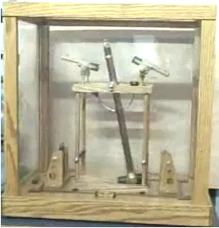 The pendulum itself looks rather like a sledgehammer due to it's rigid shaft and the additional magnets mounted on the weight. The above picture shows the pendulum at the end of it's swing to the right and the picture below, in it's extreme left hand swing position: 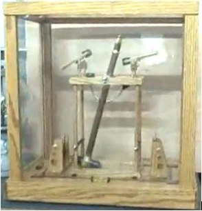 Which indicates the swing covers a fairly short distance. Mounted near the top of the pendulum, there are two pivoted arms which look quite like microphones, due to having large magnets mounted on their innermost ends: 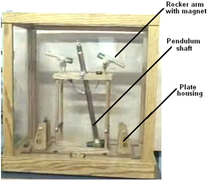 The device operates like this: The pendulum swings to the right and as it does so, it raises a magnet attached to the pendulum shaft by a curved silver arm: 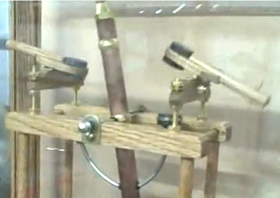 Presumably, the arm is curved to avoid the constructional complications at the pendulum pivot which would be caused by a straight mounting arm attached to the pendulum shaft. The rising magnet attached to the pendulum pushes the magnet end of the rocker arm upwards even though it does not come close to it. The rocker arm is used to raise and lower a plate which has a magnet mounted in it. The raising and lowering is achieved by having two cords attached to the end of the rocker arm and their other ends attached to the two upper corners of the moving plate: 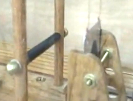 The plate slides in two slots in the support housing and the plate movement is relatively small: 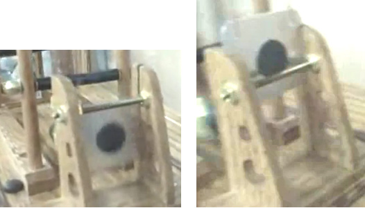 The tipping up of the lever arm drops the plate down as the pendulum approaches the plate. This introduces a magnetic braking effect where some of the momentum of the pendulum weight is stored in the opposing magnetic fields of the pendulum magnets and the plate magnet. This brakes the pendulum movement and gives it a magnetic push on its opposite swing, sustaining it's swinging day after day after day. This is a clever arrangement and the device on display has been built to a very high standard of construction. It does not appear to have any additional energy take off, but seems quite likely that air-core coils could be used along the swing path to generate electrical power. The arrangement appears so close to John Bedini's pendulum battery charger that it may well be possible to use a pendulum of this type to charge batteries just as John does. While this looks like a very simple device, it is highly likely that it requires exact adjustment of the length of the lever arms, the magnetic gap sizes in relation to the strength of the magnets, etc. etc. Repeated small adjustments are probably needed to get the device operating smoothly and sustaining the pendulum swing. All in all though, it is a very interesting device. Gravitational Effects. We are all familiar with the effects of gravity. If you drop something, it falls downwards. Engineers and scientists are usually of the opinion that useful work cannot be performed on a continuous basis from gravity, as, they point out, when a weight falls and converts it’s “potential energy” into useful work, you then have to put in just as much work to raise the weight up again to its starting point. While this appears to be a sound analysis of the situation, it is not actually true. Some people claim that a gravity-powered device is impossible because, they say that it would be a “perpetual motion” machine, and they say, perpetual motion is impossible. In actual fact, perpetual motion is not impossible as the argument on it being impossible is based on calculations which assume that the object in question is part of a “closed” system, while in reality, it is most unlikely that any system in the universe is actually a “closed” system, since everything is immersed in a massive sea of energy called the “zero-point energy field”. But that aside, let us examine the actual situation. Johann Bessler made a fully working gravity wheel in 1712. A 300 pound (136 Kg) wheel which he demonstrated lifting a 70 pound weight through a distance of 80 feet, demonstrating an excess power of 5,600 foot-pounds. Considering the low level of technology at that time, there would appear to be very little scope for that demonstration to be a fake. If it were a fake, then the fake itself would have been a most impressive achievement. However, Bessler acted in the same way as most inventors, and demanded that somebody would have to pay him a very large amount of money for the secret of how his gravity wheel worked. In common with the present day, there were no takers and Bessler took the details of his design to the grave with him. Not exactly an ideal situation for the rest of us. However, the main argument against the possibility of a working gravity wheel is the idea that as gravity appears to exert a direct force in the direction of the earth, it therefore cannot be used to perform any useful work, especially since the efficiency of any device will be less than 100%. While it is certainly agreed that the efficiency of any wheel will be less than 100% as friction will definitely be a factor, it does not necessarily follow that a successful gravity wheel cannot be constructed. Let us apply a little common sense to the problem and see what results. If we have a see-saw arrangement, where the device is exactly balanced, with the same length of a strong plank on each side of the pivot point, like this:  It balances because the weight of the plank (“W”) to the left of the support point tries to make the plank tip over in a counter-clockwise direction, while exactly the same weight (“W”) tries to tip it over in a clockwise direction. Both turning forces are d times W and as they match exactly, the plank does not move. The turning force (d times W) is called the “torque”, and if we alter the arrangement by placing unequal weights on the plank, then the beam will tip over in the direction of the heavier side:  With this unequal loading, the beam will tip down on the left hand side, as indicated by the red arrow. This seems like a very simple thing, but it is a very important fact. Let me point out what happens here. As soon as the weight on one side of the pivot is bigger than the weight on the other side (both weights being an equal distance from the pivot point), then the heavy plank starts to move. Why does it move? Because gravity is pushing the weights downwards. One other point is that the distance from the pivot point is also important. If the added weights “m” are equal but placed at different distances from the pivot point, then the plank will also tip over:  This is because the larger lever arm “x” makes the left hand weight “m” have more influence than the identical weight “m” on the right hand side. Do you feel that these facts are just too simple for anyone to really bother with? Well, they form the basis of devices which can provide real power to do real work, with no need for electronics or batteries. The following suggestions for practical systems are put forward for you to consider, and if you are interested enough test out. However, if you decide to attempt to build anything shown here, please understand that you do so entirely at your own risk. In simple terms, if you drop a heavy weight on your toe, while other people may well be sympathetic, nobody else is liable or responsible for your injury - you need to be more careful in the future ! Let me stress it again, this document is for information purposes only.  The Dale Simpson Gravity Wheel. The design of gravity-operated machines is an area which has been of considerable interest to a number of people for quite some time now. The design shown here comes from Dale Simpson of the USA. It should be stressed that the following information is published as open-source, gifted to the world and so it cannot be patented by any individual or organisation. Dale’s prototype wheel has a diameter of about five feet, utilising weights of a substantial value. The overall strategy is to create excess torque by having the weights slide along metal rods radiating from a central hub somewhat like the spokes of a cart wheel. The objective is to create an asymmetrical situation where the weights are closer to the hub when rising, than they are when falling. The difficulty with designing a system of this type is to devise a successful and practical mechanism for moving the weights in towards the hub when they are near the lowest point in their elliptical path of movement. Dale’s design uses a spring and a latch to assist control the movement of each weight. The key to any mechanical system of this type is the careful choice of components and the precise adjustment of the final mechanism to ensure that operation is exactly as intended. This is a common problem with many free-energy devices as careless replication attempts frequently result in failure, not because the design is at fault, but because the necessary level of skill and care in construction were not met by the person attempting the replication. Here is a sketch of Dale’s design:  The wheel has an outer rim shown in blue and a central hub shown in grey. Metal spokes shown in black run out radially from the hub to the rim. Eight spokes are shown in this diagram as that number allows greater clarity, but a larger number would probably be beneficial when constructing a wheel of this type. The wheel as shown, rotates in a counter-clockwise direction. Each weight, shown in dark grey, has a pair of low-friction roller bearings attached to it. There is also a spring, shown in red, between the weight and the hub. When a weight reaches the 8-o’clock position, the roller bearings contact a spring compression ramp, shown in purple. This ramp is formed of two parts, one on each side of the spokes, providing a rolling ramp for each of the two roller bearings. The ramp is formed in a curve which has a constant rate of approach towards the hub of the wheel. The ramp is positioned so that the spring is fully compressed when the weight has just passed the lowest point in its travel. When the spring is fully compressed, a latch holds it in that position. This holds the weight in close to the hub during its upward movement. The springs are not particularly powerful, and should be just strong enough to be able to push the weight back towards the rim of the wheel when the spoke is at forty five degrees above the horizontal. The “centrifugal force” caused by the rotation assists the spring move the weight outwards at this point. The push from the spring is initiated by the latch being tripped open by the latch release component shown in pink. The weights have an inward motion towards the hub when they are pushed by the wheel’s turning motion which forces the roller bearings upwards along the spring-compression ramp. They have an outward motion along the spokes when the catch holding the spring compressed is released at about the 11-o’clock position. The latch and the release mechanism are both mechanical - no electronics or electrical power supply is needed in this design. These details are shown in the diagram below:  The question, of course is, will there be enough excess power to make the wheel rotate properly? The quality of construction is definitely a factor as things like the friction between the weights and their spokes needs to be very low. Let us consider the forces involved here:  Take any one weight for this calculation. Any excess rotational energy will be created by the difference between the forces attempting to turn the wheel in a clockwise direction and those forces trying to turn the wheel in a counter-clockwise direction. For the purpose of this discussion, let us assume that we have built the wheel so that the compressed-spring position is one third of the spring-uncompressed position. As the weights are all of the same value “W”, the see-saw turning effect in a clockwise direction is the weight (“W”) multiplied by it’s distance from the centre of the axle (“L”). That is, W x L. The turning effect in the counter clockwise direction is the weight (“W”) multiplied by it’s distance from the centre of the axle (“3W”). That is, W x 3 x L. So, with WL pushing it clockwise, and 3WL pushing it counter-clockwise, there is a net force of (3WL - WL), i.e. a net force of 2WL driving the wheel in a counter-clockwise direction. If that force is able to push the weight in towards the hub, compressing the spring and operating the spring latch, then the wheel will be fully operational. There is actually, some additional turning power provided by the weights on the left hand side of the diagram, both above and below the horizontal, as they are a good deal further out from the axle than those with fully compressed and latched springs. The only way of determining if this design will work correctly is to build one and test it. It would, of course, be possible to have several of these wheels mounted on a single axle shaft to increase the excess output power available from the drive shaft. This design idea has probably the lowest excess power level of all those in this document. The following designs are higher powered and not particularly difficult to construct. The Veljko Milkovic Pendulum / Lever system. The concept that it is not possible to have excess power from a purely mechanical device is clearly wrong as has recently been shown by Veljko Milkovic at his web site where his two-stage pendulum/lever system shows a COP = 12 output of excess energy. COP stands for “Coefficient Of Performance” which is a quantity calculated by diving the output power by the input power which the operator has to provide to make the system work. Please note that we are talking about power levels and not efficiency. It is not possible to have a system efficiency greater than 100% and it is almost impossible to achieve that 100% level. Here is Veljko’s diagram of his very successful lever / pendulum system:  Here, the beam 2 is very much heavier than the pendulum weight 4. But, when the pendulum is set swinging by a slight push, the beam 2 strikes down on anvil 1 with considerable force, certainly much greater force than was needed to make the pendulum swing. As there is excess energy, there appears to be no reason why it should not be made self-sustaining by feeding back some of the excess energy to maintain the movement. A very simple modification to do this could be:  Here, the main beam A, is exactly balanced when weight B is hanging motionless in it’s “at-rest” position. When weight B is set swinging, it causes beam A to oscillate, providing much greater power at point C due to the much greater mass of beam A. If an additional, lightweight beam D is provided and counterbalanced by weight E, so that it has a very light upward pressure on its movement stop F, then the operation should be self-sustaining. For this, the positions are adjusted so that when point C moves to its lowest point, it just nudges beam D slightly downwards. At this moment in time, weight B is at its closest to point C and about to start swinging away to the left again. Beam D being nudged downwards causes its tip to push weight B just enough to maintain its swinging. If weight B has a mass of “W” then point C of beam A has a downward thrust of 12W on Veljko’s working model. As the energy required to move beam D slightly is quite small, the majority of the 12W thrust remains for doing additional useful work such as operating a pump. The Dale Simpson Hinged-Plate System. Again, this is an open-source design gifted by Dale to the world and so cannot be patented by any person, organisation or other legal entity. This design is based on the increased lever arm of the weights on the falling side compared to the lesser lever arm on the rising side:  This design uses heavy metal plates which are carried on two drive belts shown in blue in the diagram above. These plates are hinged so that they stand out horizontally on the falling side, resting on a pair of lugs welded to the chain link and hang down vertically on the rising side as they are narrower than the gap between the belts. This difference in position alters the effective distance of their weights from the pivot point, which in this case is the axle of wheel “C”. This is exactly the position described above with the see-saw with equal weights placed at different distances from the pivot. Here again, the distance “x” is much greater than the distance “d” and this causes a continuous turning force on the left hand side which produces a continuous force turning the drive shaft of wheel “C” in a counter-clockwise direction as seen in the diagram. A key point in this design are the robust hinges which anchor the heavy metal plates to the belt. These are designed so that the plates can hang down and lie flat on the rising side (point “B”) but when the plate passes over the upper wheel to reach point “A”, and the plate flips over, the hinge construction prevents the plate from moving past the horizontal. The upper wheel at point “A” is offset towards the falling side so as to help reduce the length “d” and improve the output power of the device. The chain detail below, shows the inside view of one of the right-hand chain plates. The metal plate swings clear of the chain and the sprocket wheels which the chain runs over.  It should be noted that the movement of the lowest edge of the plates as they turn over when moving past the upper wheel at point “A”, is much faster than anywhere else, and so putting a protective housing around it would definitely be advisable as you don’t want anybody getting hit by one of these heavy plates. It is, of course, possible to make this device to a much smaller scale to demonstrate it’s operation or test different chain designs. The plates could be made from chipboard which is fairly heavy for its size and relatively cheap. The Murilo Luciano Gravity Chain. Murilo Luciano of Brazil, has devised a very clever, gravity-operated power device which he has named the “Avalanche-drive”. Again, this design cannot be patented as Murilo has gifted it to the world as a royalty-free design which anybody can make. This device continuously places more weights on one side of a drive shaft to give an unbalanced arrangement. This is done by placing expandable links between the weights. The links operate in a scissors-like mode which open up when the weights are rising, and contract when the weights are falling:  In the arrangement shown here, the weights are shown as steel bars. The design is scaleable in both height, width and the mass and number of weights. In the rough sketch above, the practical details of controlling the position of the bars and co-ordinating the rotation of the two support shafts are not shown in order to clarify the movement. In practice, the two shafts are linked with a pair of toothed sprockets and a chain. Two sets of vertical guides are also needed to control the position of the bars when they are in-between the four sprockets which connect them to the drive shafts, and as they go around the sprocket wheels. In the sketch, there are 79 bar weights. This arrangement controls these so that there are always 21 on the rising side and 56 on the falling side (two being dead-centre). The resulting weight imbalance is substantial. If we take the situation where each of the linking bars weighs one tenth as much as one of the bar weights, then if we call the weight of one link “W”, the rising side has 252 of these “W” units trying to turn the sprockets in a clockwise direction while 588 of the “W” units are trying to turn the sprockets in an counter-clockwise direction. This is a continuous imbalance of 336 of the “W” units in the counter-clockwise direction, and that is a substantial amount. If an arrangement can be implemented where the links open up fully, then the imbalance would be 558 of the “W” units (a 66% improvement) and the level arm difference would be substantial. There is one other feature, which has not been taken into account in this calculation, and that is the lever arm at which these weights operate. On the falling side, the centre of the weights is further out from the axis of the drive shafts because the link arms are nearly horizontal. On the rising side, the links are spread out over a lesser horizontal distance, so their centre is not as far out from their supporting sprocket. This difference in distance, increases the turning power of the output shafts. In the sketch above, an electrical generator is shown attached directly to one output shaft. That is to make the diagram easier to understand, as in practice, the generator link is likely to be a geared one so that the generator shaft spins much faster than the output shaft rotates. This is not certain as Murilo envisages that this device will operate so rapidly that some form of braking may be needed. The generator will provide braking, especially when supplying a heavy electrical load. This diagram shows how the two side of the device have the unbalanced loading which causes a counter-clockwise rotation:  The diagrams shown above are intended to show the principles of how this device operates and so for clarity, the practical control mechanisms have not been shown. There are of course, many different ways of controlling the operation and ensuring that it works as required. One of the easiest building methods is to link the two shafts together using a chain and sprocket wheels. It is essential to have the same number of bar weights passing over the upper sprocket wheels as pass under the lower sprocket wheels. On the upper sprocket wheels, the bars are spread out, say, three times as far apart than they are on the lower sprocket wheels, so the upper sprockets need to rotate three times as fast as the lower ones. This is arranged by using a lower drive-chain sprocket wheel which has three times the diameter of the upper one. The driving force provided by the weight imbalance of the two columns of rod weights needs to be applied to the lower sprocket wheels at point “A” in the diagram above. For this to happen, there has to be a mechanical connection between the stack of bar weights and the sprocket wheel. This can be done in different ways. In the above concept diagrams, this link has been shown as a sprocket tooth or alternatively, a simple pin projection from the sprocket wheel. This is not a good choice as it involves a considerable amount of machining and there would need to be some method to prevent the bar rotating slightly and getting out of alignment with the sprocket wheel. A much better option is to put spacers between the bar weights and have the sprocket teeth insert between the bars so that no bar slots are needed and accurate bar positioning is no longer essential. This arrangement is shown below:   The description up to here has not mentioned the most important practical aspects of the design. It is now time to consider the rising side of the device. To control the expanded section of the chain, and to ensure that it feeds correctly on to the upper sprocket wheels, the gap between successive bar weights must be controlled.  A guiding channel can be used, as shown here, and standard ball-bearings or roller-bearings can be attached to the ends of the weights by using threaded rod (or a bolt with the head inside the weight) and locking nuts. In the example shown here, which is of course, just one option out of hundreds of different implementations, the bars on the rising side are three times as far apart as those on the falling side. This means that on the upper sprocket wheels, only every third tooth will connect with a bar weight. This is shown in the following diagram. However, if the linked weights were left to their own devices, then the rising side bars would hang down in one straight line. While that would be optimum for drive power, Murilo does not envisage that as a practical option, presumably due to the movement of the links as the bar weights move over their highest point. In my opinion, that arrangement is quite possible to implement reliably provided that the length of the links is selected to match the sprocket distance exactly, however, Murilo’s method is shown here. Murilo’s method is to use additional restraining links between the weights. The objective here is to make sure that when the weights spread out on their upward journey, that they take up positions exactly three bar widths apart, and so feed correctly on to the teeth of the upper sprocket wheel. These links need to close up on the falling side and open up on the rising side. They could be fabricated from short lengths of chain or from slotted metal strips with a pin sliding along the slot. Whichever method is chosen, it is important that the links stay clear of the bars and do not prevent the bars stacking closely together on the falling side as that would prevent them seating correctly on the teeth of the lower sprocket wheels. The easiest precision option for the home constructor is using chain, where two bar weights are positioned on the upper sprocket wheel to give the exact spacing, and the tensioned chain is welded in position, as shown below. Placing the chain inside a plastic tube causes it to take up an “A” shape standing outwards from the links when they move into their closed position. This keeps the chains from getting between the link bars. In addition, the chains are staggered from one pair of link bars to the next, as shown below, as an additional measure to keep the operation both reliable and quiet.. In the diagram below, only a few of these restraining links are shown in order to keep the diagram as simple as possible. It is not a good choice to make the upper bar sprocket wheels three times larger than the lower sprocket wheels as this would force both the rising and falling sections of chain out of the vertical, which in turn introduces friction against the guides. The central 1:3 gearing is needed to make sure that the chains on the rising side are fully stretched and the spacing of the bar weights matches the upper sprocket spacing exactly.  The diagrams have not shown the supporting framework which holds the axles in place and maintains the unit in a vertical position, as this framing is not specialised in any way, and there are many acceptable variations. A sensible precaution is to enclose the device in an upright box cabinet to make sure that there is no chance of anything getting caught in the rapidly moving mechanism. This is an impressive design of Murilo’s, who recommends that in the implementation shown above, that the links shown in blue are made 5% longer than those shown in yellow, as this improves the weight distribution and drive of the lower sprocket wheel.. A washing machine has a maximum power requirement of 2.25 kW and in the UK a suitable 3.5 kW alternator costs £225 and needs to be spun at 3,000 rpm for full output. While the above description covers Murilo’s main design, it is possible to advance the design further, raising its efficiency in the process as well as reducing the construction effort needed to build it. For this version, the main components remain the same, with the upper axle geared to the lower axle as before and the upper axle rotating faster than the lower one. The main difference is that on the rising side, the chain opens up completely. This does away with the need for the chain links, moves the rising weights much closer in and reduces the number of rising weights:  With a reduced number of weights in the diagram above, the weight imbalance is a very substantial 40:11 ratio with the massive advantage of a substantially reduced lever arm “d” which is much smaller than the lever arm “x” of the falling weights. This is a major imbalance, giving 40x pulling the axle in a counter-clockwise direction and only 11d opposing that movement. In the description so far, it has been assumed that all components will be made of metal. This is not necessarily the best choice. Firstly, metal moving against metal does make a noise, so guides made robustly of thick plastic or other similar material would be a good choice for the guides for the weights. The weights themselves could equally well be made from strong plastic piping filled with sand, lead pellets, concrete or any other convenient heavy material. The pipes would then have strong end caps capable of holding the pivots for the links. The sprocket wheels themselves could well be made from thick plastic material which would give a quieter operation and which could be bolted to the power take-off shaft with a bolt placed right through the axle. Most of the dimensions are not critical. Increasing the diameter of the lower sprocket wheel will increase the power of the output axle but will lower its speed. Adding more weights will increase both the output power and to a lesser degree, the speed, but will increase the overall size of the unit and its overall weight and cost. Making each weight heavier will raise the output power, or reduce the overall size if the weight is contained in fewer weights. Increasing the length of the links means fewer weights on the rising side but will require larger sprocket wheels. It is not necessary to have all the links the same size. If the lengths are chosen carefully and the indentations in the upper sprocket wheel cover the entire circumference, then every second link can be one indentation shorter which tips the weights into a more compact and effective column on the falling side:   With this arrangement, the outer weights, shown here on the left, press down very firmly on the inside column of weights, making a compact group. If using plastic pipes with concrete then the hinge arrangement for the rods can be very simple, with a bolt set in the concrete as shown below. The rods, washers and bolt can be supported on a thin, rigid strip placed across the top of the pipe. When the concrete has gone solid, the strip is removed and the gap produced by its removal then allows free movement of the rods. If this technique is used, then the bar weights are cast in two steps, with a tightly fitting disc pushed part way up inside the pipe so that one end can be filled while the other end remains open and ready for the completion of the other end. One advantage of using plastic pipes is that if the sprocket wheels are made from a tough high-density plastic material, such as is used for food chopping boards, and the weight guides are also made from tough plastic, then there should be no metal-upon-metal noise produced during operation, if the bolt holes in the connecting rods are a good fit for the bolts used. The concrete or mortar used as a filling can be made wet and pliable, since mechanical strength is not an issue here, and a filling with no voids in it is desirable. Even low quality concrete (caused by more water than absolutely necessary) would be more than adequate for this purpose. The arrangement at the ends of a concrete-filled plastic pipe bar weight could be constructed like this:  There is a very strong inclination when building a device to make it operate smoothly. Where excess energy is being drawn from the gravity field, the reverse is necessary, with a jerky operation being the optimum. Remember that the extra energy only occurs during the duration of the impulses causing the jerks. It follows then, that in an ideal situation, any device of this type should be driven by a rapid series of strong impulses. In practice, using a heavy flywheel or any similar component which has a high inertial mass, although a rapid series of sharp pulses is being applied to the component and jerky operation is not visible to the human eye, excess energy is still being “led-out” and made available to do useful work. One other observation which may be of interest, and that it the feedback from builders of gravity wheels which says that the power output from a gravity wheel is greater if the axle is horizontal and the rotating wheel is aligned exactly with magnetic East-West. A Practical Construction Query I have just been asked about the practical issues of mounting the guiding components for the weights. I must apologise for not making it clear that the diagrams in this description are intended to show the overall methods of operation, rather than being a direct construction arrangement. There will be several ways of constructing an implementation of each device. Here is one suggestion for a practical construction method for the gravity chain device. The query was as follows:  It is pointed out that the lower guide as shown, can't be supported from inside as the weights sweep through the area which would be used for that support. Also, it can't be supported from outside as the connecting rods have to move through the area where that support would be positioned. A solution has been suggested where the lower guide is supported by a strap from the upper guide, the strap running between the inner and outer weights. That is a solution which could work, but it introduces significant unnecessary friction. An alternative method is to place the guides outside the moving weights as shown here:  This method provides a low-friction channel for the roller-bearings to move along. This controls the position of the weights very accurately and the end walls also provide the supports for the axels which synchronise the positions of the weights and provide gearing between the axels if that is required. For clarity, just two of the many weights are shown and the overall proportions distorted so that the diagram will fit on the page. With the axels, it might look like this:  Here, the axel shafts are geared together outside the end wall and either a chain or a belt drive used. The lower shaft allows a power take-off. The ratio of the diameters of the pulley wheels or sprocket wheels dictates the relative rates of rotation of the two shafts. Ivan Monk's Rotary Power Unit. This patent is a combination of a gravity-operated device and a heat-pump. Energy is drawn from the surrounding environment and used to cause a weight imbalance which then utilises gravity to cause the rotation of the motor shaft. This invention is described as a device for powering toys and other non-serious applications, however, when used to drive the magnetic shields of an Ecklin-Brown electrical generator, it might well become a serious power-generating device. 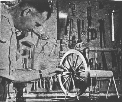 The device operates by using the temperature difference between a horizontal tube cooled by a damp cloth cover and a hollow spoked wheel. Freon inside the device is continually evaporating in the wheel section and condensing in the horizontal tube. A simple valve arrangement then allows the liquid freon to flow back into the spokes of the wheel at a time when gravity can provide a turning force on the wheel. Presumably, when built to a convenient size, the power of this device will be very limited. 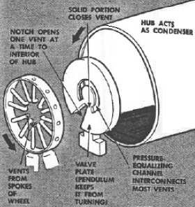 Ivan patented his design because he felt that it was possible that it might be used to power small devices such as toys or clocks. The cloth sleeve over the horizontal tube can be kept wet by a loop of string which goes down into a container of water. Here is the patent: DESCRIPTION The present invention relates to a power unit for amusement devices, toys, clocks, or the like, and more particularly to a rotary power unit which requires no fuel but which operates under conditions of small differences if temperature. Toys, clocks, amusement and advertising devices and the like, which have moveable parts, require some type of motive power for their operation and this motive power is usually supplied by a motor of one kind or another, such as electrical, vibratory or spring-driven, and in each case a power source is needed, whether it be a battery, a spring or something else. It has been found that such devices need considerable attention, and in order for them to function constantly, they must be rewound, reset or the batteries replaced at frequent intervals. Over a period of time, this procedure becomes not only bothersome but also expensive. The present invention is self-contained and self-sufficient for power purposes and it will operate indefinitely solely by the heat of the surroundings, with practically no attention or supervision, and in addition, it is comparatively inexpensive to manufacture. Furthermore, the device will operate over long periods of time and needs no resetting, rewinding or batteries. The exact nature of this invention will be readily understood from the following description and drawings where: Fig.1. Shows a perspective view of a preferred embodiment of the invention:  Fig.2. Shows a sectional view taken along line 2--2 of Fig.1, looking in the direction of the arrows:  Fig.3. Shows a sectional view taken along line 3--3 of Fig.2, looking in the direction of the arrows:  Fig.4. Is an enlarged sectional view of the wheel and hub, taken along line 4--4 of Fig.2, looking in the direction of the arrows:  Fig.5. Shows a sectional view taken along line 5--5 of Fig.2, looking in the direction of the arrows:  Fig.6. Illustrates an enlarged perspective view of the valve plate and pendulum elements of the valve assembly:  Fig.7. Shows an enlarged view of the pendulum:  Fig.8. Illustrates a modification of the valve assembly where floats are used instead of a pendulum. This view is taken along line 8--8 of Fig.9 looking in the direction of the arrows:  Fig.9. is an end view, taken along the line 9--9 of Fig.8 looking in the direction of the arrows:  Fig.10. is a perspective view of the float assembly:  Fig.11. shows an alternative position for the filling plug:  Fig.12. is a view showing a modification of the invention:  Fig.13. is a view along line 13--13 of Fig12, looking in the direction of the arrows:  In each drawing, the numbers used for any component are the same in each view shown. In Fig.1 the perspective view shows the power unit which has the general appearance of a wheel 11 with a cylinder 12. which is attached to the hub 13 of the wheel. The cylinder 12 has an end cap 14 which is sealed to it. Wheel 11 which is described in more detail later on, has a metal hub 13 and the cylinder 12 is also made of a thin metal such as brass, copper or something similar. The joints between the cylinder 12, the hub 13, and the end cap 14, are soldered, sweated or brazed to form inside the cylinder 12 a hermetically sealed compartment capable of containing a fluid under pressure, or a vacuum, without leaking. Rigidly attached to hub 13 is a hub shaft 15 which is supported in bearings 16, which in turn are mounted in pedestal 17. At the opposite end of cylinder 12, and rigidly attached to end cap 14, is a hollow cap shaft 18 which is supported in bearings 21, which in turn are mounted in pedestal 22. Ideally, the entire power unit is mounted so that it can rotate as freely as possible, so any well-known means such as jewel bearings can be used to mount the supporting shafts. A screwed filling plug 23 is placed in the exposed end of cap shaft 18. This hermetically seals cylinder 12 after the working fluid is inserted through the hollow shaft 18. The working fluid is described in detail later on. Completely encasing the entire outer surface of cylinder 12, is a wick 24, made from cloth or similar material, which when it is dampened with water or other fluid, acts to cool cylinder 12 through evaporation. For continued operation of the device over long periods of time, any well-known method of keeping wick 24 wet, such as a siphon system (not shown) or a continual drip pipe 24a, may be used.  The element 11, which has the general appearance of a wheel, consists of a hollow rim 25, which is concentric with the axis of cylinder 12 and hub 13. Rim 25 is held rigidly to hub 13 by several equally-spaced hollow spokes 26. Each of these spokes connects to the interior of cylinder 12 by means of a passage 26a in the hub. The rim 25, is constructed using any light weight material which has good heat-conducting properties and it can have a cross-section of any convenient shape. For example, it could be a square cross-section as shown in Fig.1 and Fig.2, or it could perhaps, be a circular shape. Other forms may also be used, provided that the internal volume of the rim and spokes is approximately uniform around the wheel. Experience has shown that for efficient operation of the power unit, any transfer of heat from the higher temperature region of the rim 25 to the lower temperature region of the cylinder 12, by conduction along the spokes 26, should be kept to a minimum. This may be achieved by making the spokes as thin as possible and making them from a material which is a poor conductor of heat, such as glass, plastic, thin brass, nickel-silver, or the like, or by using a layer of insulating material, or synthetic rubber and cement between the surfaces of the spokes and the hub 13. Partially filling the hollow interior of the wheel assembly 11, and the cylinder 12, is a volatile liquid 27, whose vapour fills the remaining space inside the device when all air and relatively non-condensable gases have been removed. It is desirable that the liquid 27 be some non-corrosive fluid having a boiling point (at atmospheric pressure) at somewhat below that of water and that it also have the fluid characteristics of low viscosity, high liquid specific gravity, large changes in vapour pressure for small changes in temperature, low specific heat for vapour and liquid, large specific volume for the vapour and low latent heat of vaporisation. Liquids such as trichloroethylene, methylene chloride, and those of the "freon" class such as trichloromonofluoromethane, dichlorotetrafluoroethane or trichlorotrifluoroethane or the like have been found satisfactory since they readily form a vapour at the temperature of the rim 25, and just as readily condense back into a liquid in the relatively cool confines of cylinder 12.  Inside cylinder 12, and free to rotate in its mounting on shaft 15, is a valve assembly 31 consisting of a valve plate 32, a pendulum 33 and a spring 34. Concentric with shaft 15 is a short sleeve 35, which is mounted on bearings 36, and held in position by means of a nut 37 and washer 38. Mounted on sleeve 35 and free to move, is valve plate 32, which is better seen in the enlarged view of Fig.6:  The valve plate 32 is a circular plate with a radial slot 41 which extends from its outer edge to about half way to its inner diameter and with a width approximately equal to the diameter of the passages 26a through the hub 13. The valve plate 32 acts as a self-aligning sliding seal over the ends of the passages 26a in the hub which lead to the spokes 26 and slot 41 allows individual spokes to connect to the inside of cylinder 12, one at a time as will be described fully later on. The valve plate 32 also contains, on its hub side, a circular groove (as shown in Fig.6) whose ends terminate on each side of slot 41, so that the distances 43 between the slot and each end of the groove is approximately equal to or slightly greater than the diameter of the passage openings 26a, which allows the distance 43 to block the opening to one spoke while the groove 42 allows the pressure to equalise between the other spokes whose passages 26a connect with the groove. While the entire valve assembly 31 is constructed so that it is prevented by pendulum 33 from rotating when wheel 11 rotates, it is desirable that the friction between hub 13 and valve plate 32 is kept to a minimum, and it has been found that when the valve plate is made from carbon or brass, it accomplishes this desired result. The pendulum 33 consists of a curved piece of lead which is rigidly attached to sleeve 35 by means of a strap 44 and bolts 45, so that the pendulum hangs below sleeve 35 and forms an integral part of it. Inserted through the lower part of pendulum 33, and held in place by nut 46, is a guide pin 47 which extends beyond the pendulum towards valve plate 32, parallel with shaft 15. Pin 47 is positioned somewhat to one side of the vertical, with the entire pendulum and strap 44 located along the length of sleeve 35 so that pin 47 extends into slot 41 (or other suitable recess in valve plate 32) thereby maintaining the slot at an angle of the order of 20 to 50 degrees from the vertical as shown in Fig.3 and Fig.5.  The angle of the slot which gives the best performance is discussed later on. Spring 34 is wound concentrically about sleeve 35 and held in compression between valve plate 32 and the pendulum strap 44 which holds the valve plate sufficiently tightly against hub 13 to provide a seal, but at the same time, not tight enough to prevent the plate from sliding when the wheel rotates. During operation, the pendulum remains stationary, keeping the valve plate stationary, causing it to operate as a sliding valve which successively opens and closes the passages 26a which connect to the spokes.  The modification shown in Fig.8 illustrates a variation of the valve assembly and its method of support, where twin floats are used to maintain the angle of the valve plate. Here, a pair of light metal floats 51 extend for most of the length of cylinder 12. These light metal float cylinders are closed at the ends and they have triangular plates 53 attached to their ends:  Supporting rod 54 is attached securely to plates 53 and is taped at its ends in order to fit into jewel bearings 55 at each end of cylinder 12. On the lower edge of the plate 53 which is nearest to the hub 13, there is lug through which is mounted the guide pin 47, secured by nuts 57. As before, the guide pin is offset to one side of the vertical centreline of plate 53. In the modification of Fig.8, the cap shaft 18 is hollow and a portion of its length is threaded as at 58, so that it can be screwed ion and out of end cap 14, allowing slight adjustments in the contact between support rod 54 and jewel bearings 55. Nut 61 is integral with shaft 18 for making the adjustment, and lock nut 62 holds it secure while packing or sealing ring 63 forms a tight joint between end cap 14, shaft 18 and lock nut 62. Filling plug 23 screws into the end of hollow shaft 18 to make an air-tight connection, after liquid 27 has been inserted, there being sufficient clearance between support rod 54 and jewel bearings 55 for the liquid to pass between them and into cylinder 12. Fig.11 is a view of an alternative method of locating the filling plug 23 by placing it in the side of cylinder 12, with the inner end flush with the inside surface of the cylinder, rather than in the end of the hollow shaft 18, but if this is done, then a small counterweight should be place diametrically opposite to the plug in order to maintain the balance of the cylinder. During operation, the rotation of the power unit is obtained by restricting the flow of vapour to a limited number of passages so that a non-symmetrical distribution of the liquid is maintained in the spokes. This unbalanced distribution of mass causes rotation due to the action of gravity. When setting up the power unit to operate for the first time, filling plug 23 is removed from cap shaft 18 and the volatile liquid 27 is inserted into the cylinder 12, care being taken to remove all of the air and relatively non-condensable gases before resealing with plug 23. Enough liquid is put into the device to cover the lower portion of cylinder 12 and the lower portion of hollow wheel rim 25 as well as a portion of the lowermost spokes 26, as seen in Fig.2 and Fig.4. Next, the wick 24 is dampened and in a few moments the power unit will automatically begin to rotate and it will continue to rotate so long as wick 24 is kept wet. Once liquid 27 has been placed in the device, it does not normally need replacing. When the unit is in operation, it should be noted that broadly speaking, the liquid 27 vaporises in the wheel and re-condenses in the cylinder. The wheel being relatively warm, approaching room temperature, readily vaporises the volatile liquid 27 to form a pressure inside the hollow rim 25 and most of the spokes 26. When the vapour passes through passages 26a into the cooler confines of cylinder 12, which is made relatively cool by the evaporation of the water in wick 24, the vapour immediately re-condenses, forming a relatively low pressure within the cylinder. As shown in Fig.4, the rotation of the wheel is in a clockwise direction as seen in that view. The valve plate 32 is held stationary by its pendulum 33 while hub 13 and spokes 26 (as well as the external wheel assembly) rotate, the valve plate 32 being held by the pin 47 on pendulum 33 so that the entering side of slot 41 is set at an angle "x" to the vertical. The angle "x", which may be from 20 to 50 degrees, is such that when a spoke is in the approximate position of spoke A (Fig.4), further rotation will cause slot 41 to uncover passage 26a thereby connecting spoke A with cylinder 12 so as to permit vapour to flow from the spoke to the cylinder, and at the same time, permit excess liquid to flow from the cylinder into the spokes and rim. As the pressure in the spoke decreases, the higher pressure in the rim forces liquid into the spoke, tending to fill the spoke with liquid, and this process continues as the spoke travels past the position of spoke B.  Finally, as the spoke approaches a vertical position, the spoke passage 26a is covered by the surface 43 (Fig.6) on the valve plate, which surface is at least as great as the diameter of 26a, thereby stopping further flow of the vapour, or liquid if the spoke has been filled completely, from the spoke to the cylinder. Further movement of the spoke causes its passage 26a to be uncovered by the end of the circular groove 42, thereby equalising the spoke pressure with that in the circular groove. It should be noted that the groove 42 simultaneously connects all of the spokes, except for those which are opposite the flat surfaces 43 and the slot 41, as at positions A and B. When the passage 28a is uncovered by groove 42, this causes the liquid level in the spoke to fall immediately to that in the rim 25, as shown in position C, so that as the spoke moves away from the vertical position it contains less liquid than it did while approaching the vertical position. This process is repeated for each succeeding spoke with the result that those spokes between position A and the vertical contain more liquid than those between the vertical and position D, and the resulting unsymmetrical distribution of liquid causes the unit to rotate. The cycle of operation for the modification of Fig.8 is the same as that for the version shown in Fig.2, the floats 51 and guide pin 47 holding valve plate 32 stationary so that the entering side of the slot makes an angle "x" with the vertical. Experience has shown that several variables influence the optimum angle of travel during which the spokes 26 connect with cylinder 12 via the slot 41 in valve plate 32. Large angles cause the unbalanced liquid to have a greater turning force around the axis of rotation, however, this requires a higher liquid level in the rim 25 (since the "active" spokes should have their lower ends submerged) and the retarding effect of the liquid, which does not rotate with the wheel, is greater. Tests of units geometrically similar to those shown here, indicate that the optimum angle ranges from 20 to 50 degrees although the power unit will operate at angles somewhat above and below those figures. The Passages 26a leading from the spokes to the cylinder 12 should be large enough to prevent capillary action from sealing off the vapour flow as the condensenate drains back in the opposite direction. Tests indicate that for circular passages, a diameter of about 3/16" (5 mm) or greater is satisfactory, although diameters somewhat smaller may be used with liquids having small surface tensions. Furthermore, smoother operation results when the passages 26a and valve plate slot 41 are proportioned so that the slot uncovers and entering passage before the leaving passage is covered. In other words, slot 41 may be so proportioned that for an instant, both spokes A and B are connected to cylinder 12 as they move toward the vertical, thereby increasing the average torque produced by the unbalanced liquid.  Increased efficiency of operation may be obtained by the addition of fins 19 (Fig.12 and Fig.13) which may be circular discs placed around the circumference of the cylinder 12, or other means for extending the surface area of the cylinder, or by constructing the rim and spokes (which are receiving heat from the atmosphere) from a material which has a high heat absorption factor, or by coating the surface with a thin layer of dull black paint. Furthermore, a light bulb 20 (Fig.12) or any other source of low intensity heat may be directed on the rim and spokes, in which case the wick 24 may not be required, since cylinder 12 will be maintained at a temperature lower than at the rim, due to radiation and convection to the surroundings. Thus, from the above specification, it can be clearly seen that this is a rotary power unit which operates under conditions of small temperature differences, one which operates without fuel but on energy obtained from the atmosphere, one whose working fluid is hermetically sealed within the power unit, and one which can be used for training, advertising, amusement, etc. Patrick Kelly engpjk@yahoo.co.uk http://www.free-energy-info.co.uk/ |