There are three categories of
pulsed system and we will consider each in turn. These are
drive-pulsed systems, energy-tapping pulsed systems and gravity
free-energy pulsing systems. Here we will look at systems
where an electrical pulse is used to cause the device to operate by
creating a temporary magnetic field caused by electric current flowing
through a coil or “electromagnet” as it is often called. Many
of these systems are rather subtle in the way that they operate. One
very well-known example of this is
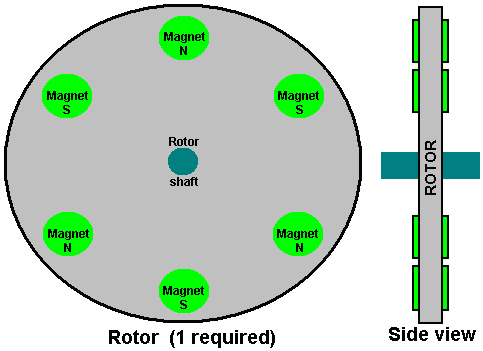
The Adams
Motor. The late Robert Adams, an electrical engineer of New
Zealand designed and built an electric motor using permanent magnets on
the rotor and pulsed electromagnets on the frame of the motor.
He found that the output from his motor exceeded the input power by a
large margin (800%).

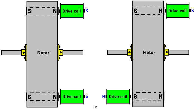
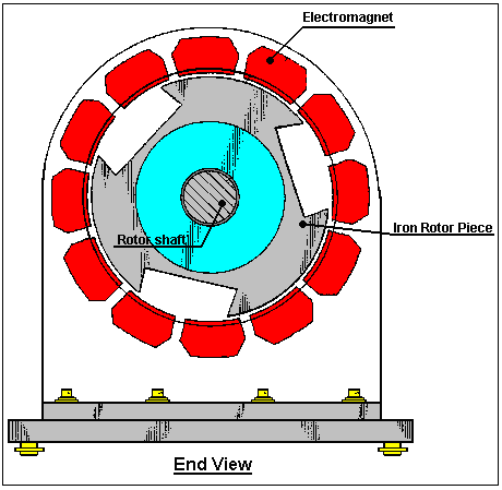
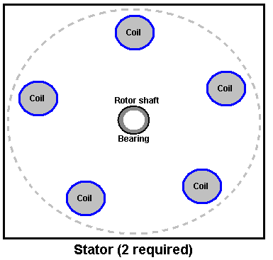
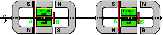
The diagram of his
motor intended to show the basic operating principle is shown here:
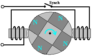
If a motor is built
like this, then it will most certainly work but it will never reach 100%
efficiency let alone exceeding the 100% mark. It is only with a specific
configuration which is hardly ever publicised that high performance
figures can be achieved. While Robert has shown several different
configurations, in order to avoid confusion I will describe and explain
just one of them. I am indebted to several of Robert's friends and
colleagues for the following information and I should like to express my
thanks to them for their help and support in bringing you this
information.
First and foremost, high performance can only be
achieved with the clever use of power collection coils. These coils need
to be positioned accurately and their power collection restricted to just
a very short arc of operation by connecting them to, and disconnecting
them from, the output circuit at just the right instant so that the back
EMF generated when the current draw stops, actually contributes to the
drive of the rotor, speeding it on it's way and raising the overall
efficiency of the motor/generator as a whole.
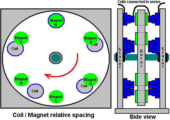
Next, the shape of
the magnets used is important as the length to width proportion of the
magnet alters the pattern of it's magnetic fields. In direct opposition to
the diagram shown above, the magnets need to be much longer than their
width (or in the case of cylindrical magnets, much longer than their
diameter).
Further, a good deal of experimentation has shown that
the size and shape of the electromagnets and pick-up coils has a major
influence on the performance. The cross-sectional area of the core of the
pick-up coils should be four times that of the cross-sectional area of the
permanent magnets in the rotor. The reverse is true for the cores of the
drive coils as their cores should have a cross-sectional area of just one
quarter of the rotor magnet cross-sectional area.
Another point
which is almost never mentioned is the fact that big circuit gains will
not be achieved unless the drive voltage is high. The minimum should be 48
volts but the higher the voltage, the greater the energy gain, so voltages
in the 120 volts (rectified US mains voltage) to 230 volts (rectified
mains voltage elsewhere) should be considered. Neodymium magnets are not
recommended for drive voltages under 120 volts.
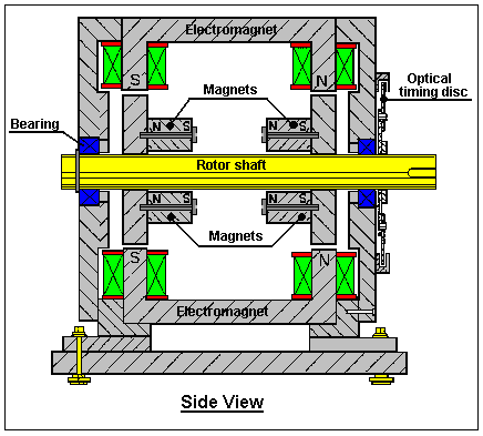
This is one of
Robert's test circuits:
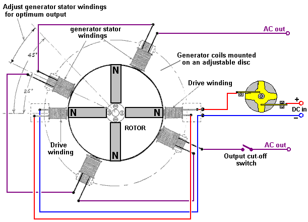
Notice that the
cores of the "generator" pick-up coils are very much wider than the cores
of the drive coils. Also notice the proportions of the magnets where the
length is much greater than the width or diameter. The four generator
windings are mounted on a single disc allowing them to be moved through an
angle to find the optimum operating position before being locked in
position and the two drive coils are mounted separately and held clear of
the disc. Notice also that the power pick-up coils are much wider compared
to their length than the drive coils are. This is a practical feature
which is explained in greater detail later.
The DC input is shown
passing through Robert's custom-made contactor switch which is mounted
directly on the shaft of the motor/generator. This is a mechanical switch
which allows an adjustable On / Off ratio, which is known as the
"Mark/Space Ratio" or, if the "On" period is of particular interest, the
"Duty Cycle". Robert Adams indicates that when the motor is running and
has been adjusted to it's optimum performance, then the Mark/Space ratio
should be adjusted to minimise the On period and ideally get it down to
about 25% so that for three quarters of the time, the input power is
actually switched off. There are various ways of achieving this switching
while still having a very sharp turn on and turn off of the power.
Robert considered mechanical switching of the drive current to be
a very good option although he was not opposed to using the contact to
power a transistor to do the actual switching and so reduce the current
through the mechanical contacts by a major factor. His reasons for his
preference for mechanical switching are that it gives very sharp
switching, needs no electrical power to make it operate and it allows
current to flow in both directions. The current flow in two directions is
important because Robert produced various ways of getting the motor to
feed current back into the driving battery, allowing it to drive the motor
for long periods without lowering its voltage hardly at all. His preferred
method of switching is shown here:
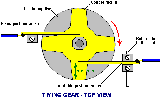
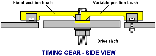
This switching gear
operates as follows: The timing disk is bolted securely to the drive shaft
of the motor and its position is set so that the electrical switch-on
occurs when the rotor magnet is exactly aligned with the drive coil core.
Adjustment of that timing is done by loosening the locking nut, rotating
the disc very slightly and clamping the disc in position again. A spring
washer is used to keep the assembly tight when the device is running. The
disc has a star-shaped piece of copper sheet set into its surface and two
silver-tipped, copper arm "brushes" slide across the surface of the copper
star.
One of these two brushes is fixed in position and slides
across the copper star near the drive shaft, making a permanent electrical
connection to it. The second brush slides alternatively on the
non-conducting surface of the disc and then over the conducting arm of the
copper. The second brush is mounted so that its position can be adjusted
and, because the copper arms taper, that alters the ratio of the "On" time
to the "Off" time. The actual switching is achieved by current flowing
through the first brush, through the copper arm and then through the
second brush. The brush arms shown in the diagram above rely on the
springiness of the copper arm to make a good brush-to-copper electrical
connection. It might be preferred to use a rigid brush arm, pivot it and
use a spring to ensure a very good contact between the brush and the
copper star at all times.
The adjustment of the On to Off time, or
"Mark/Space Ratio" or "Duty Cycle" as the technical people describe it,
could perhaps do with some description. If the moveable brush is
positioned near the centre of the disc, then, because of the tapering of
the copper arms, the part of the non-conducting disc that it slides over
is shorter and the part of the conducting copper arm with which it
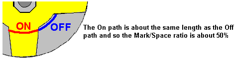
connects is longer, as the two sliding paths are about the same length,
the current is on for about the same length as it is off, giving a
Mark/Space ratio of about 50% as shown here:
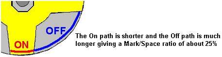
If, instead, the
moveable brush is positioned near the outside edge of the disc, then
because of the tapering of the copper arm, the On path is shorter and the
non-conducting Off path is very much longer, being about three times as
long as the On path, giving a Mark/Space ratio of about 25%. As the
moveable brush can be positioned anywhere between these two extremes, the
Mark/Space ratio can be set to any value from 25% to 50%.
The two brushes can
be on the same side of the drive shaft or on opposite sides as shown. One
important feature is that the brushes touch in a position where the disc
surface is always moving directly away from the brush mounting, causing
any drag to be directly along the arm and giving no sideways loading on
the brush. The diameter of the device is usually one inch (25 mm) or less.
You will also notice that the output is switched although the
diagram does not give any indication of how or when that switching takes
place. You will notice that the diagram has angles marked on it for the
optimum positioning of the pick-up coils, well, an Adams Motor builder
with a forum ID of "Maimariati" who achieved a Coefficient Of Performance
of 1,223, found that the optimum switching for his motor is On at 42
degrees and Off at 44.7 degrees. That tiny 2.7 degree part of the rotor
turn gives a substantial power output and cutting the output current off
at that point causes the back EMF of the coils to give the rotor a
substantial additional boost on its way. His input power is 27.6 watts and
his output power is 33.78 kilowatts
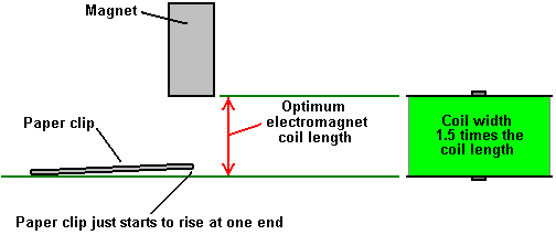
Now for some practical
details. It is suggested that a good length for the power pick-up coils
can be determined by using the “paper clip test”. This is done by taking
one of the permanent magnets used in the rotor, and measuring the distance
at which that magnet just begins to lift one end of a 32 mm (1.25 inch)
paper clip off the table. The optimum length of each coil from end to end
is exactly the same as the distance at which the paper clip starts to
lift.
The core material
used in the electromagnets can be of various different types including
advanced materials and alloys such as ‘Somalloy’ or 'Metglas'. The power
pick-up coil proportions are important as an electromagnet becomes less
and less effective as its length increases, and eventually, the part
furthest from the active end can actually be a hindrance to the effective
operation. A good coil shape is one which you would not expect, with the
coil width being, perhaps 50% greater than the coil length:
Contrary to what you would expect, the device draws in energy from
the local environment better if the end of the pick-up coil farthest from
the rotor is left unaffected by any other part of the device and the same
applies to the magnet facing it. That is, the coil should have the rotor
at one end and nothing at the other end, that is, no second rotor behind
the coil. The speed at which the voltage is applied to, and removed from,
the coils is very important. With very sharp voltage rises and falls,
additional energy is drawn from the surrounding environmental energy
field. If using transistor switching, then the IRF3205 FET has been found
to be very good and a suitable driver for the FET is the MC34151.
If using a Hall-effect semiconductor to synchronise the timing,
say the UGN3503U which is very reliable, then the life of the Hall-effect
device is much improved if it is provided with a 470 ohm resistor between
it and the positive supply line, and a similar 470 ohm resistor between it
and the negative line. These resistors in series with the Hall-effect
device effectively “float” it and protect it from supply-line spikes".
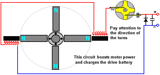
Here, two
electromagnets are driven by the battery via Robert's 4-arm commutator
which is mounted on the rotor shaft. Some of the recommendations given by
Robert are the opposite of what you would expect. For example, he says
that a single rotor construction tends to be more electrically efficient
that one where several rotors are mounted on a single shaft. Robert is
against the use of reed switches and he recommends making one of his
commutators.
At one stage, Robert recommended the use of standard
transformer shims for constructing the cores of the electromagnets. This
has the advantage that matching bobbins for holding the coil windings are
readily available and can still be used for pick-up coils. Later on,
Robert swung towards the use of solid cores from the old PO Series 3000
telephone relays and eventually said that electromagnet cores should be
solid iron.
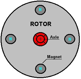
The diagrams
presented by Robert show the magnets located on the rim of the rotor and
pointing outwards. If this is done, then it is essential that the magnets
in the rotor are firmly attached on at least five of their six faces and
the possibility of using a ring of non magnetic material such as duct tape
around the outside should be considered. That style of construction also
lends itself to streamlining the rotor by having a completely solid
construction, although it might be remarked that the motor would run
better and more quietly if it were enclosed in a box which had the air
pumped out of it. If that is done, then there will be no air resistance
and because sound can't pass through a vacuum, quieter operation is bound
to result.
While this may sound a bit complicated, there is no
reason why it should be. All that is needed is two discs and one central
disc which is the thickness of the magnets, with slots cut in it, the
exact size of the magnets. The assembly starts with the lower disc,
magnets and central disc. These are glued together, probably with epoxy
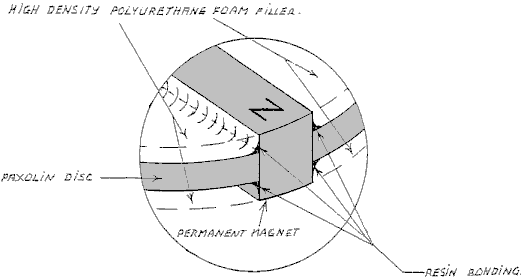
resin, and that holds the magnets securely on four faces as shown here:
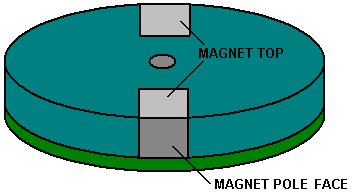
Here, the magnets
are attached on the lower face, the right and left faces, and the unused
pole face, and when the upper disc is attached, the upper faces are also
secured and there is the minimum of air turbulence when the rotor spins:
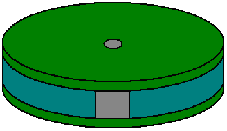
There is a "sweet
spot" for the positioning of the power pick-up coils and it will usually
be found that this is two or three millimeters away from the rotor. If
that is the case, then there will be room for an outer band of duct tape
on the rim of the rotor to provide additional protection against the
failure of the magnet attachment method.
High-power versions of
the motor/generator need to be enclosed in a metal box which is earthed as
they are quite capable of generating a substantial amount of high
frequency waves which can damage equipment such as oscilloscopes and
create TV reception interference. There would probably be an improvement
in performance as well as a reduction in sound if the box was airtight and
had the air pumped out of it. If that is done, then there will be no air
resistance as the rotor spins and since sound does not pass through a
vacuum, quieter operation is possible.
Experienced rotor builders
do not like the radial magnets style of construction because of the
stresses on the magnet attachments if high rotational speeds are reached.
It should not need to be said, but it is obviously a major requirement to
keep your hands well away from the rotor when the motor is running as it
is perfectly possible to be injured by the high-speed movement if you are
careless. Please remember that this presentation must not be considered to
be a recommendation that you build or use any device of this nature and it
must be stressed that this text, in common with the entire contents of
this eBook, is intended to be for information purposes only and no
representations or warranties are implied by this presentation. Should you
decide to construct, test or use any device, then you do so entirely at
your own risk and no liability attaches to anybody else if you sustain any
kind of injury or property damage as a result of your own actions.
Because of the mechanical stresses caused during rotation, some
experienced constructors feel that the magnets should be embedded in the
rotor as shown here where they are kept well clear of the rim of a rotor
which is made from a tough material. This is so that the outer strip of
the material prevents the magnets breaking loose and becoming dangerous
high-speed projectiles, which at best would destroy the electromagnets and
at worst could injure someone quite badly:
It needs to be
remembered that the proportions of the magnets are for the magnet length
to be more than the diameter, so in cases like this where circular magnet
faces are to be used, the magnets will be cylindrical and the rotor needs
to have a significant thickness, which will depend on the magnets which
are available locally. The magnets should be a tight push-fit in their
holes and securely glued in place.
Robert Adams has used this
construction style as well. However, if an arrangement like this is used,
then there will be a substantial sideways pull on the rotor as it reaches
the electromagnet core, tending to pull the magnets out of the rotor.
It is important
that the rotor should be perfectly balanced and have the minimum amount of
bearing friction possible. This calls for precision construction and
either roller or ball bearings. The construction style shown above has the
distinct advantage that it has an open end to both the magnet and the
coils and this is believed to facilitate the inflow of environmental
energy into the device.
It may be my ignorance showing here, but I
have a problem with the version on the right (which is considered by some
to be the optimum arrangement). The difficulty as I see it is that the
magnet/core pull and the subsequent drive thrust when the coil is powered,
form a "turning couple" as they both tend to rotate the axle in the same
direction. This places a substantial loading on the axle bearings, usually
amplified by the radius of the rotor being greater than the distance from
the rotor to the axle bearings. This load will be in the tens of kilograms
range and will be applied and reversed perhaps forty times per second. To
me, that appears like a vibration load and is directly opposed to the
"perfectly balanced" rotor operation being sought. The radial magnet
arrangement generally shown by Robert Adams does not have any of this kind
of loading at all because the coils are exactly opposite each other and
their loads cancel each other out exactly. The choice is, of course, up to
the builder and his assessment of the advantages and disadvantages of the
different styles of construction.
When getting ball-race bearings
for an application like this, please be aware that "closed" bearings such
as these are not suitable as supplied:
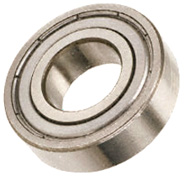
This is because
this type of bearing is usually packed with dense grease which completely
destroys its free motion, making it worse as a bearing than a simple
hole-and-shaft arrangement. However, in spite of this, the closed or
"sealed" bearing is popular as the magnets tend to attract dirt and dust
and if the device is not enclosed in a steel box as is necessary for the
high power versions, then having the seal is considered to be an
advantage. The way to deal with the grease packing is to soak the bearing
in an isopropyal solvent cleaner to remove the manufacturer's grease, and
then, when it has dried out, lubricate the bearing with two drops of a
high quality thin oil. If it is intended to house the motor/generator in
an earthed, sealed steel box then an alternative type of bearing which
might be suitable is an open design like this:
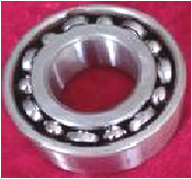
especially if the
air is removed from the box. Some constructors perfer to use ceramic
bearings which are supposed to be immune to dirt. One supplier is here
but as with everything else, these choices have to be made by the builder
and will be influenced by his opinions.
I'm not sure where it came
from, but here is a circuit diagram showing a transistor drive and the
return of the back EMF of the drive coils to the driving power supply.
Using this method, about 95% of the drive current can be returned,
lowering the current draw enormously:
The diode feeding
the power back to the supply is a Schottky type because of it's high-speed
operation. It needs to be able to handle the peak pulse power and so
should be one of the more robust types. What this circuit does not have is
the very important switching on the output coils circuit. Another strange
item is the way that the FET sensor is arranged with two sensors rather
than one and with an additional battery. While it must be admitted that
the current draw of the FET gate should be very low, there still does not
seem to be much reason to have a second power supply. One other
peculiarity in this diagram is the positioning of the drive coils. With
them offset as shown, it has the effect of them being at an angle relative
to the rotor magnets. It is not at all clear if this is an advanced
operating technique or just poor drawing - I am inclined to assume the
latter although I have no evidence for this other than the circuit design
and the low quality of the original drawing which had to be improved
considerably to arrive at the diagram shown above.
The coil
generator output should be fed into a capacitor before being passed to
whatever equipment is to be powered by the device. This is because the
energy is being drawn from the local environment and is not conventional
energy. Storing it in a capacitor converts it to a more normal version of
electrical power, a feature which has also been mentioned by Don Smith and
by John Bedini although their devices are quite different in operation.
The DC resistance of the coil windings is an important factor. The
overall resistance should be either 36 ohms or 72 ohms for a complete set
of coils, whether they are drive coils or power pick-up coils. Coils can
be wired in parallel or in series or in series/parallel. So, for 72 ohms
with four coils, the DC resistance of each coil could be 18 ohms for
series-connected, 288 ohms for parallel connected, or 72 ohms for
connection in series/parallel where two pairs of coils in series are then
wired in parallel.
To help with assessing the wire diameter and
length which you could use, here is a table of some of the common sizes in
both American Wire Gage and Standard Wire Gauge:
So far, we have not
discussed the generation of the timing pulses. A popular choice for a
timing system is to use a slotted disc mounted on the rotor axle and
sensing the slots with an "optical" switch. The "optical" part of the
switch is usually performed by UV transmission and reception and as ultra
violet is not visible to the human eye, describing the switching mechanism
as "optical" is not really correct. The actual sensing mechanism is very
simple as commercial devices are readily available for performing the
task. The sensor housing contains both a UV LED to create the transmission
beam, and a UV dependent resistor to detect that transmitted beam.
Here is an example of a neatly constructed timing mechanism made
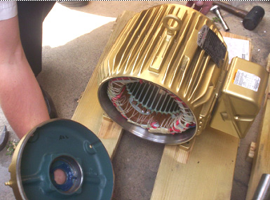
by Ron Pugh for his six-magnet rotor assembly:
This device happens
to be one which is supplied here under their product code
number : OP-5490-14327-00. As the slotted disc rotates, one of the slots
comes opposite the sensor and allows the UV beam to pass through to the
sensor. That lowers the resistance of the sensor device and that change is
then used to trigger the drive pulse for whatever length of time the slot
leaves the sensor clear. You will notice the balanced attachment method
used by Ron to avoid having an unbalanced rotor assembly. There can be two
timing discs, one for the drive pulses and one for switching the power
pickup coils in and out of the circuit. The slots in the power pick-up
timing disk will be very narrow as the switch-on period is only about 2.7
degrees. For a six-inch diameter disc where 360 degrees represents a
circumference length of 18.85 inches (478.78 mm) a 2.7 degree slot would
be only 9/64 inch (3.6 mm) wide. The arrangement for an axial magnet rotor
set-up could be like this:
So to recap, the
things which are necessary for getting an Adams Motor output into the
serious bracket are:
- A performance of COP>1 can only be achieved if there are power
pick-up coils.
- The rotor magnets need to be longer than they are wide in order to
ensure the correct magnetic field shape and the rotor must be perfectly
balanced and have bearings as low-friction as possible.
- The face area of the rotor magnets needs to be four times that of
the drive coil cores and one quarter the area of the core of the power
pick-up coils. This means that if they are circular, then the drive coil
core diameter needs to be half the diameter of the magnet and the magnet
diameter needs to be half the diameter of the power pick-up core. For
example, if a circular rotor magnet is 10 mm across, then the drive core
should be 5 mm across and the pick-up core 20 mm across.
- The drive voltage needs to be a minimum of 48 volts and preferably,
a good deal higher than that.
- Do not use neodymium magnets if the drive voltage is less than 120
volts.
- The drive coils should not be pulsed until they are exactly aligned
with the rotor magnets even though this does not give the fastest rotor
speed.
- Each complete set of coils should have a DC resistance of either 36
ohms or 72 ohms and definitely 72 ohms if the drive voltage is 120 volts
or higher.
- Collect the output power in large capacitors before using it to
power equipment.
If you want the original drawings and some
explanation on the operation of the motor, then two publications from
the late Robert Adams can be bought from www.nexusmagazine.com where the
prices are quoted in Australian dollars, making the books look much more
expensive than they actually are.
This website
is a location for Adams motor enthusiasts and may have information which
might be helpful.
Here is a really
impressive collection of well-informed practical material on building
and using an Adams motor with details of sensors and how they work, core
materials and their performances and how to locate the "sweet spot" -
very highly recommended web site.
Raymond Kromrey.
Where the objective is to produce electricity from a rotating
magnetic field, there has always been a search for some method of either
reducing, or eliminating altogether, the drag on the rotor when electric
current is drawn from the generator. One design which claims to have
very limited drag caused by current draw is the Kromrey design. The main
characteristics of this design are said to be:
1. It has
almost constant electrical power output even when the rotor speed is
altered by as much as 35%.
2. It can continue to operate with
it's electrical output short-circuited, without heating the rotor or
causing a braking effect.
3. The production efficiency
(electrical output divided by the driving force) is high.
4.
The frequency of it's AC output power can be adjusted to that required
by the equipment which it powers.
5. The rotor can be spun at
any rate from 800 rpm to 1,600 rpm.
6. The simple construction
allows manufacturing costs to be about 30% less than other
generators.
7. This generator is recommended for supplying
power at or above the 1 kilowatt level.
Here is the patent
for this device:
Patent US 3,374,376 19th March 1968 Inventor: Raymond Kromrey ELECTRIC
GENERATOR
My present invention relates to an
electric generator which converts magnetic energy into electric energy
using two components which can rotate relative to each other, i.e. a
stator and a rotor, one having electromagnets or permanent magnets which
induce a voltage in a winding which forms part of an output circuit
mounted on the other component.
Conventional generators of this
type use a winding which whose conductors form loops in different axial
planes so that opposite parts of each loop pass through the field of
each pole pair, twice per revolution. If the loops are open circuit,
then no current flows in the winding and no reaction torque is
developed, leaving the rotor free to turn at the maximum speed of its
driving unit. As soon as the output winding is connected across a load
or is short-circuited, the resulting current flow tends to retard the
motion of the rotor to an extent which depends on the intensity of the
current and this makes it necessary to include compensating
speed-regulating devices if it is necessary to maintain a reasonably
constant output voltage. Also, the variable reaction torque subjects the
rotor and its transmission to considerable mechanical stresses and
possible damage.
It is therefore the general object of this
invention to provide an electric generator which has none of the above
disadvantages. Another object is to provide a generator whose rotor
speed varies very little in speed between open circuit operation and
current delivery operation. Another objective is to provide a generator
whose output voltage is not greatly affected by fluctuations in its
rotor speed.
I have found that these objectives can be achieved
by rotating an elongated ferromagnetic element, such as a bar-shaped
soft-iron armature, and a pair of pole pieces which create an air gap
containing a magnetic field. Each of the outer extremities of the
armature carries a winding, ideally, these windings are connected in
series, and these coils form part of a power output circuit used to
drive a load. As the armature rotates relative to the air gap, the
magnetic circuit is intermittently completed and the armature
experiences periodic remagnetisations with successive reversals of
polarity.
When the output circuit is open, the mechanical energy
applied to the rotor (less a small amount needed to overcome the
friction of the rotating shaft) is absorbed by the work of
magnetisation, which in turn, is dissipated as heat. In actual practice
however, the resulting rise in temperature of the armature is hardly
noticeable, particularly if the armature is part of the continuously
air-cooled rotor assembly. When the output circuit is closed, part of
this work is converted into electrical energy as the current flow
through the winding opposes the magnetising action of the field and
increases the apparent magnetic reluctance of the armature, and so the
speed of the generator remains substantially unchanged if the output
circuit is open or closed.
As the armature approaches its
position of alignment with the gap, the constant magnetic field tends to
accelerate the rotation of the armature, aiding the applied driving
force. After the armature passes through the gap there is a retarding
effect. When the rotor picks up speed, the flywheel effect of its mass
overcomes these fluctuations in the applied torque and a smooth rotation
is experienced.
In a practical embodiment of this invention, the
magnetic flux path includes two axially spaced magnetic fields
traversing the rotor axis and substantially at right angles to it. These
fields are generated by respective pole pairs co-operating with two
axially spaced armatures of the type already described. It is convenient
to arrange these two armatures so that they lie in a common axial plane
and similarly, the two field-producing pole pairs also lie in a single
plane. The armatures should be laminated to minimise eddy currents, so
they are made of highly permeable (typically, soft-iron) foils whose
principle dimension is perpendicular to the rotor axis. The foils can be
held together by rivets or any other suitable method.
If the
ferromagnetic elements are part of the rotor, then the output circuit
will include the usual current-collecting means, such as slip-rings or
commutator segments, depending on whether AC or DC current output is
desired. The source of coercive force in the stator includes,
advantageously, a pair of oppositely positioned, yoke-shaped magnets of
the permanent or electrically energised type, whose extremities
constitute the pole pieces mentioned above. If electromagnets are used
in the magnetic circuit, then they may be energised by an external
source or by direct current from the output circuit of the generator
itself.
I have found that the terminal voltage of the output
circuit does not vary proportionately to the rotor speed as might be
expected, but instead, it drops at a considerably slower rate with
decreasing rotor speed. So, in a particular tested unit, this voltage
fell to only about half its original value when the rotor speed was
dropped to one third. This non-linear relationship between terminal
voltage and driving rate produces a substantially constant load current
and therefore, electric output over a wide speed range, at least under
certain load conditions, inasmuch as the inductive reactance of the
winding is proportional to frequency (and consequently, to rotor speed)
so as to drop off more rapidly than the terminal voltage, in the event
of a speed reduction, with a resulting improvement in the power factor
of the load circuit.
If the magnetic circuit contains only a
single pole pair per air gap, the flux induced in the rotating armature
will change its direction twice per revolution so that each revolution
produces one complete cycle of 360 electrical degrees. In general, the
number of electrical degrees per revolution will equal 360 times the
number of pole pairs, it being apparent that this number ought to be odd
since with even numbers it would not be possible to have poles
alternating in polarity along the path of the armature and at the same
time to have the North and South poles of each pair at diametrically
opposite locations. In any case, it is important to dimension the curved
facing faces of the pole pairs in such a manner so as to avoid allowing
the armature to bridge between adjoining poles, so it is necessary to
make the sum of the arcs spanned by these faces (in the plane of
rotation) equal to considerably less than 360 degrees electrical.
The invention will now be described in more detail, reference
being made to the accompanying drawings in which:
Fig.1 and
Fig1A. illustrate a first embodiment of my invention, shown in
axial section and in a cross-sectional view taken on line IA - IA
of Fig.1 respectively.
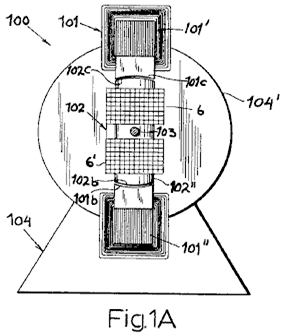
Fig.2 and
Fig.3 are perspective views illustrating two other embodiments.


Fig.4 and
Fig.5 illustrate diagrammatically, two output circuit
arrangements, one for a DC output and one for an AC output.
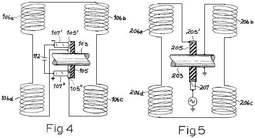
Fig.6 is a
somewhat diagrammatic illustration of an arrangement for comparing the
outputs of a conventional generator and a generator according to this
invention.
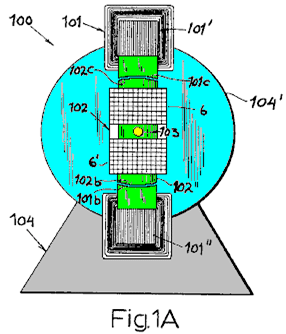
The generator
100 shown in Fig.1 and Fig.1A comprises a stator
101 and a rotor 102 which has a pair of laminated
armatures 102' and 102", carried on a shaft 103
which is free to rotate in bearings mounted in the end plates
104' and 104", of a generator housing 104 which is
made from non-magnetic material (e.g. aluminium) which is rigidly
attached to the stator.
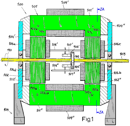
Shaft 103
is coupled to a source of driving power indicated diagrammatically by an
arrow 110. The stator 101 includes a pair of yoke-shaped
laminated electromagnets 101' and 101" whose extremities
form two pairs of co-planar pole pieces, designated respectively
101a, 101b (North magnetic pole) and 101c, 101d (South
magnetic pole). The pole pieces have concave faces, facing towards the
complimentary convex faces 102a, 102d of armature 102' and
102b, 102c of armature 102". These faces whose
concavities are all centred on the axis of shaft 103, extend over
arcs of approximately 20o to 25o each in the plane
of rotation (Fig.1A) so that the sum of these arcs adds up to
about 90o geometrically and electrically.
The stator
magnets 101', 101" are surrounded by energising windings 109',
109" which are connected across a suitable source of constant direct
current (not shown). Similar windings, each composed of two
series-connected coils 106a, 106d and 106b, 106c, surround
the rotor armatures 102' and 102", respectively. These
coils form part of an output circuit which further includes a pair of
brushes 107', 107" which are carried by arms 108', 108" on
housing 104 with mutual insulation brushes 107', 107"
co-operate with a pair of commuter segments 105', 105" (see also
Fig.4) which are supported by a disc of insulating material
105, mounted on shaft 103.
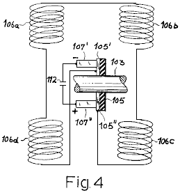
By virtue of the
series-connection of coils 106a-106d between the segments
105' and 105", as illustrated in Fig.4, the
alternating voltage induced in these coils gives rise to a rectified
output voltage at brushes 107' and 107". The
unidirectional current delivered by these brushes to a load (not shown)
may be smoothed by conventional means, represented by capacitor
112 in Fig.4.
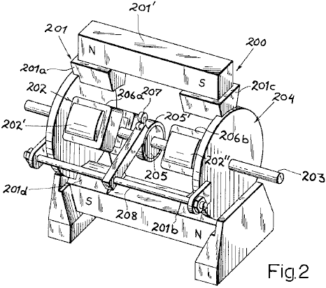
Fig.2,
shows a modified generator 200, whose housing 204,
supports a stator 201 essentially consisting of two permanent bar
magnets 201' and 201", extending parallel to the drive
shaft 203 (on opposite side of it), each of these magnets being
rigid and each having a pair of sole shoes 201a, 201c and
201b, 201d respectively. Rotor 202 is a pair of laminated
armatures 202' and 202",similar to those of the previous
embodiment, whose output coils 206a, 206b, 206c and 206d
are serially connected between a slip-ring 205', supported on
shaft 203 through the intermediary of an insulating disc
205, and another terminal here represented by the grounded shaft
203 itself. Slip-ring 205' is contacted by brush
207 on holder 208, the output of this brush being an
alternating current of a frequency determined by the rotor speed.
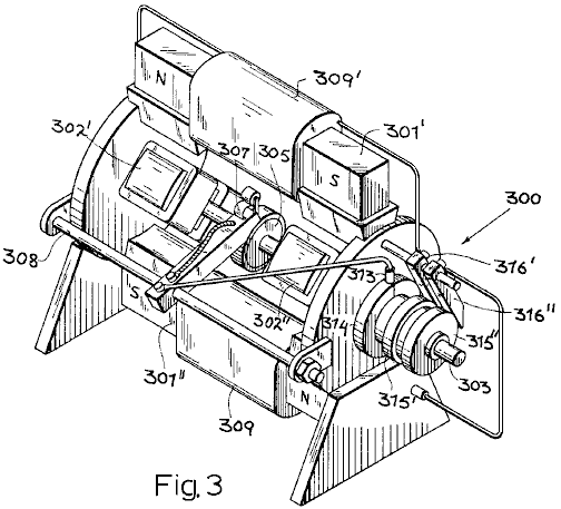
Fig.3
shows a generator 300 which is basically similar to the generator
100 shown in Fig.1 and Fig.1A. It's shaft
303 carries a pair of laminated soft-iron armatures 302',
302" which can rotate in the air gaps of a pair of electromagnets
301', 301" which have windings 309' and 309". The
commutator 305 again co-operates with a pair of brushes
307, only one of which is visible in Fig.3. This brush,
carried on an arm 308, is electrically connected to a brush
313 which engages with a slip-ring 314 positioned on an
extremity of shaft 303 which also carries two further slip-rings
315', 315" which are in conductive contact with ring 314
but are insulated from the shaft. Two further brushes 316', 316"
contact the rings 315', 315" and respectively are connected to
windings 309' and 309". The other ends of these windings
are connected to an analogous system of brushes and slip-rings on the
extremity of the opposite shaft, and arranged so that the two commutator
brushes are effectively bridged across the windings 309' and
309" in parallel. Therefore, in this embodiment, the stator
magnets are energised from the generator output itself, it being
understood that the magnets 301' and 301" (made, for
example, of steel rather than soft iron) will have a residual coercive
force sufficient to induce an initial output voltage. Naturally, the
circuits leading from the brushes 307 to the windings 309',
309" may include filtering as described in connection with
Fig.4.

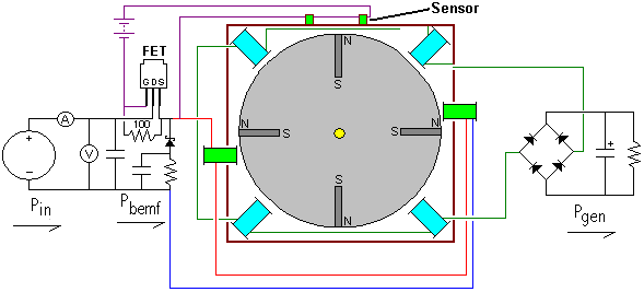
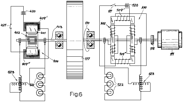
Fig.6
shows a test circuit designed to compare the outputs of a generator of
this design, such as the unit 100 of Fig.1 and
Fig.1A, with a conventional generator 400 of the type
having a looped armature 402 which rotates in the gap of a stator
magnet 401 which is fitted with energising windings 409',
409". The two generators are interconnected by a common shaft
103 which carries a flywheel 117. This shaft is coupled
through a clutch 118 to a drive motor 111 which drives the
rotors 402 and 102 of both generators in unison, as
indicated by arrow 110. Two batteries 120 and 420,
in series with switches 121 and 421, represent the method
of supplying direct current to the stator windings 109', 109" and
409', 409" of the two generators.
The rectified output of
generator 100 is delivered to a load 122, shown here as
three incandescent lamps connected in series, and with a combined
consumption of 500 watts. Generator 400, provides current into an
identical load 422. Two wattmeters 123 and 423 have
their voltage and current windings connected respectively in shunt and
in series with their associated loads 122 and 422, to
measure the electric power delivered by each generator.
When
clutch 118 is engaged, shaft 113 with it's flywheel
117 is brought to an initial driving speed of 1,200 rpm. at which
point, the switch 421 in the energising circuit of the
conventional generator 400, is closed. The lamps 422 light
immediately and the corresponding wattmeter 423 shows an initial
output of 500 watts. However, this output drops immediately as the
flywheel 117 is decelerated by the braking effect of the magnetic
field on armature 402.
Next, the procedure is repeated
but with switch 421 open and switch 121 closed. This
energises generator 100 and the lamps 122 light up,
wattmeter 123 showing an output of 500 watts, which remains
constant for an indefinite period of time , there being no appreciable
deceleration of flywheel 117. When the clutch 118 is
released and the rotor speed gradually decreases, the output of
generator 100 is still substantially 500 watts at a speed of 900
rpm. and remains as high as 360 watts when the speed dropped further to
600 rpm. In a similar test with a generator of the permanent magnet
type, such as the one shown at 200 in Fig.2, a
substantially constant output was observed over a range of 1600 to 640
rpm.
Teruo Kawai. In July 1995, a patent was granted
to Teruo Kawai for an electric motor. In the patent, Teruo states
that a measured electrical input 19.55 watts produced an output of 62.16
watts, and that is a COP of 3.18. The main sections of that
patent are included on this site.
In this
motor, a series of electromagnets are placed in a ring to form the
active stator. The rotor shaft has two iron discs mounted on it.
These discs have permanent magnets bolted to them and they have
wide slots cut in them to alter their magnetic effect. The
electromagnets are pulsed with the pulsing controlled via an optical
disc arrangement mounted on the shaft. The result is a very
efficient electric motor whose output has been measured as being in
excess of its input.
Self-Powered 800 watt Generator.
There is a video on Google which shows a self-powered electrical
generator at this
location.
This is also a generator of this general type.
Initially, the
generator is got up to speed, driven by the mains electrical supply.
Then, when it is running normally, the mains connection is
removed and the motor/generator sustains itself and is also able to
power 800 watts of lightbulbs. The generator output is normal
mains current.

The Muller
Motor. Bill Muller who died in 2004, produced a series of
very finely engineered devices, the latest of which he stated produced
some 400 amps of output current at 170V DC for 20 amps at 2V DC drive
current. The device both generates its own driving power and
produces an electrical power output. Bill’s device weighed some
90 kilos and it requires very strong magnets made of
Neodymium-Iron-Boron which are expensive and can easily cause serious
injury if not handled with considerable care.
It should be noted
that Ron Classen shows the details of his work in replicating this motor
on his web site
and he reports that he spent in excess of US $3,000 in construction and
so far, has already achieved an output power of about 170% of the input
power. A video
of his motor in action is at and his development is progressing
steadily. Ronald points out that decreasing the gap between the
rotor and the stator by just one millimetre raises the input and output
current by ten amps, so the potential of his machine is ten times
greater than its present performance. Ronald has not implemented
this as yet since the cost of the switching components is fairly high.
His construction looks like this:
The Muller
motor has a lot in common with Robert Adam’s pulsed permanent-magnet
motor. Both use a rotor which contains permanent magnets.
Both pulse electromagnets at the precise moment to achieve maximum rotor
torque. Both have pick-up coils for generating an electrical
output. There are, however, considerable differences. Bill
Muller’s coils are wound in an unusual way as shown below. He
positions his rotor magnets off-centre in relation to the stator coils.
His coils are operated in pairs which are wired in series - one
each side of the rotor. He has an odd number of coils and an even
number of permanent magnets. His magnets are positioned with alternate
polarity: N, S, N, S, ...
In order to make it easier to follow,
the diagrams below show just five coil pairs and six magnets, but much
larger numbers are normally used in an actual construction of the
device, typically sixteen magnets.
If AC mains voltage is
used then the drive wiring may be as shown here:
When adapted for
five pairs of coils, this becomes:
If DC
switching is used, then the circuit may be:
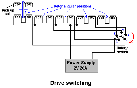
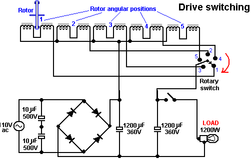
This is an unusual
arrangement made all the more peculiar by the fact that the drive
pulsing is carried out on the same coils which are used for power
generation. The driving power pulse is applied to every
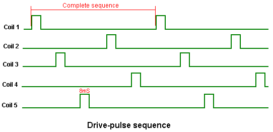
successive coil which, with just five coils, makes the drive sequence 1,
3, 5, 2, 4, 1, 3, 5, 2, 4 .... For this operation, Coil 1 is
disconnected from the power generation circuitry and then given a short
high-power DC pulse. This boosts the rotation of the rotor.
Coil 1 is then re-connected to the power generating circuitry,
and coil 3 is disconnected and then given a drive pulse. This is
repeated for every second coil, indefinitely, which is one of the
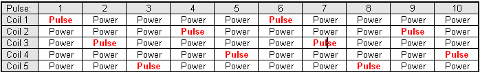
reasons why there is an odd number of coils. The following table
shows how the drive is operated.
It is essential
that Neodymium-Iron-Boron magnets are used for this device as they are
about ten times more powerful than the more common ferrite types.
Bill used sixteen magnets in the 30 - 50 MegaGaussOerstedt energy
density range, constructed in China, they held their magnetism unaltered
for eight years of use. The air gap between the coils and the
magnets is 2 mm. Bill used a computer chip to generate the
switching sequence, and Ronald Classen who is expert in these systems
points out that the pulsing system is adjusted when the motor speed
increases. This change is not a simple one as when the speed of
rotation reaches its maximum level, on a sixteen magnet rotor, only
three of the magnets would be driven by coils pulses. That is,
during one rotation, just three electromagnets would be energised in one
simultaneous pulse, and that pulse would be of longer duration than the
pulses which accelerated to rotor from its stationary position.
The output from each coil is passed through a full-wave bridge
to give DC, before being added to the output from the other coils.
A typical Muller motor would have 16 magnets and 15 coil pairs.
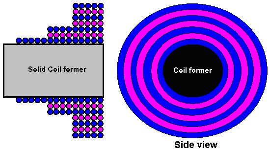
The solid coil formers were made from ‘amorphous metal’ and are 2
inches (50 mm) in diameter and 3 inches (75 mm) long. Bill used a
special mix of ‘black sand’ (probably magnetite granules) encased in
epoxy resin, but an alternative is said to be hard steel - the harder
the better. The coil core material is said to be very important
and his construction was said to be free of any hysteresis eddy
currents. The coils are wound from #6 AWG (SWG 8) or #8 AWG (SWG
10) wire and are formed in an unusual fashion as shown here:
The winding turns
are all made in the same direction. The first layer has 14 turns,
the next two layers have 9 turns each, and the remaining four layers
have 5 turns each, which gives a total of 52 turns. The coils are
used in pairs, being wired in series, with one of each pair being on the
opposite side of the rotor to the second coil of the pair, as indicated
on the drawings. The way in which the coils are connected to the
stator is not certain. The thin end of the coils face the rotor magnets.
The pick-up coils are not shown on the drawings, but they are placed on
both of the stators, in every position where there is no drive coil.
The rotor is constructed of non-magnetic material and spins at
about 3,000 rpm. This device has the potential to output 35 kW of
excess power when constructed in the size described, which has a rotor
diameter of 660 mm with the magnets centred on a circle of 570 mm.
In the demonstration which produced 35 kW of power, only five out
of the intended thirty pairs of pick-up coils had been constructed. It
is predicted that the output would be 400 horsepower if all thirty pairs
of pick-up coils were in place. Predictions of this nature need to be
borne out in a demonstration before they can be considered valid.
Please be aware of the size of this item of equipment. I
personally, would not be able to pick up a device of this weight, but
would need mechanical lifting equipment to move it. It can, of
course, be constructed in a scaled down size which will have a scaled
down electrical output.
Let me stress that handling magnets of
this strength has its dangers. Should you take a magnet in your
hand and inadvertently move your hand near a loose steel item, then your
hand is liable to become trapped between the magnet and the steel
object. This may result in serious damage to your hand.
Great care should be taken.
The official
web site for this system is which you may find difficult to display
unless you have the MacroMedia software installed on your computer.
An alternative information site on the
constructional details shows both motor details and the details of a
separate ‘over-unity’ experiment which lights four 300W light bulbs
while taking 1100W directly from the AC mains supply.
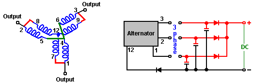
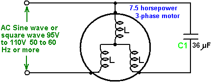
The
RotoVerter. Not all pulsed-drive systems use permanent
magnets as part of their drive mechanism. For example, the
RotoVerter systems uses standard three-phase electric motors instead of
magnets. In addition, some of the electrical driving power can be
recovered for re-use.
This system has been reproduced by several
independent researchers and it produces a substantial power gain when
driving devices which need an electrical motor to operate. At
this time, this
web site has details on how to construct the device. The
outline details are as follows:
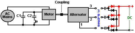
The output device
is an alternator which is driven by a three-phase mains-powered, 3 HP to
7.5 HP motor (both of these devices can be standard ‘asynchronous
squirrel-cage’ motors). The drive motor is operated in a highly
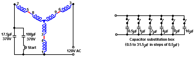
non-standard manner. It is a 240V motor with six windings as
shown below. These windings are connected in series to make an
arrangement which should require 480 volts to drive it, but instead, it
is fed with 120 volts of single-phase AC. The input voltage for
the motor, should always be a quarter of its rated operational voltage.
A virtual third phase is created by using a capacitor which
creates a 90-degree phase-shift between the applied voltage and the
current.
The objective is
to tune the motor windings to give resonant operation. A start-up
capacitor is connected into the circuit using the press-button switch
shown, to get the motor up to speed, at which point the switch is
released, allowing the motor to run with a much smaller capacitor in
place. Although the running capacitor is shown as a fixed value,
in practice, that capacitor needs to be adjusted while the motor is
running, to give resonant operation. For this, a bank of
capacitors is usually constructed, each capacitor having its own ON/OFF
switch, so that different combinations of switch closures give a wide
range of different overall values of capacitance. With the six
capacitors shown above, any value from 0.5 microfarad to 31.5 microfarad
can be rapidly switched to find the correct resonant value. These values
allow combined values of 0.5, 1.0, 1.5, 2.0, 2.5, 3.0, 3.5, .....by
selecting the appropriate switches to be ON or OFF. Should you
need a value greater than this, then wire a 32 microfarad capacitor in
place and connect the substitution box across it to test higher values
step by step to find the optimum value of capacitor to use. The
capacitors need to be powerful, oil-filled units with a high voltage
rating - in other words, large, heavy and expensive. The power
being handled in one of these systems is large and setting one up is not
without a certain degree of physical danger. These systems have
been set to be self-powered but this is not recommended, presumably
because of the possibility of runaway with the output power building up
rapidly and boosting the input power until the motor burns out.
The Yahoo EVGRAY Group at http://groups.yahoo.com/group/EVGRAY
has a large number of members, many of whom are very willing to offer
advice and assistance. A unique jargon has built up on this
forum, where the motor is not called a motor but is referred to as a
“Prime Mover” or “PM” for short, which can cause confusion as “PM”
usually stands for “Permanent Magnet”. RotoVerter is abbreviated
to “RV” while “DCPMRV” stands for “Direct Current Permanent Magnet
RotoVerter” and “trafo” is a non-standard abbreviation for
“transformer”. Some of the postings in this Group may be
difficult to understand due to their highly technical nature and the
extensive use of abbreviations, but help is always available there.
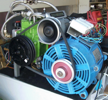
To move to some more practical construction details for this
system. The motor (and alternator) considered to be the best for
this application is the “Baldor
EM3770T” 7.5 horsepower unit. The
specification number is 07H002X790, and it is a
230/460 volts 60Hz 3-phase, 19/9.5 amp, 1770 rpm, power factor 81,
device.
The Baldor web site is here and the following details should
be considered carefully before trying any adaption of an expensive
motor. The following constructional photographs are presented here by
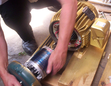
kind permission of Ashweth Palise of the EVGRAY Group.
The end
plate of the drive motor needs to be removed and the rotor lifted out.
Considerable care is needed when doing this as the rotor is heavy
and it must not be dragged across the stator windings as doing that
would damage them.
The second
end-plate is then removed and placed on the opposite end of the stator
housing.
The fan is
removed as it is not needed and just causes unnecessary drag, and the
rotor is inserted the opposite way round to the way it was removed.
That is, the housing is now the other way round relative to the
rotor, since the rotor has been turned through 180 degrees before being
replaced. The same part of the shaft of the rotor passes through
the same end plate as before as the end plates have also been swapped
over. The end plates are bolted in position and the rotor shaft
spun to confirm that it still rotates as freely as before.
To
reduce friction to an absolute minimum, the motor bearings need to be
cleaned to an exceptional level. There are various ways of doing
this. One of the best is to use a carburettor cleaner spray from
your local car accessories shop. Spray inside the bearings to
wash out all of the packed grease. The spray evaporates if left
for a few minutes. Repeat this until the shaft spins perfectly,
then put one (and only one) drop of light oil on each bearing and do not
use WD40 as it leaves a residue film. The result should be a
shaft which spins absolutely perfectly.
The next step is to
connect the windings of the two units. The motor (the “Prime
Mover”) is wired for 480 volt operation. This is done by
connecting winding terminals 4 to 7, 5 to 8 and 6 to 9. The
diagram shows 120 volts AC as being the power supply. This is
because the RotoVerter design makes the motor operate at a much lower
input than the motor designers intended. If this motor were
operated in the standard way, a 480 volt 3-phase supply would be
connected to terminals 1, 2 and 3 and there would be no capacitors in
the circuit.
It is
suggested that the jumpering of the motor windings is more neatly done
by removing the junction box cover and drilling through it to carry the
connections outside to external connectors, jumpered neatly to show
clearly how the connections have been made for each unit, and to allow
easy alterations should it be decided to change the jumpering for any
reason.
The same is done for the unit
which is to be used as the alternator. To increase the allowable
current draw, the unit windings are connected to give the lower voltage
with the windings connected in parallel as shown below with terminals
4,5 and 6 strapped together, 1 connected to 7, 2 connected to 8 and 3
connected to 9. This gives a three-phase output on terminals 1, 2
and 3. This can be used as a 3-phase AC output or as three single-phase
AC outputs, or as a DC output by wiring it as shown here:
The motor
and the alternator are then mounted securely in exact alignment and
coupled together. The switching of the direction of the housing
on the drive motor allows all of the jumpering to be on the same side of
the two units when they are coupled together, facing each other:
The input drive
may be from an inverter driven from a battery charged via a solar panel.
The system how needs to be ‘tuned’ and tested. This
involves finding the best ‘starting’ capacitor which will be switched
into the circuit for a few seconds at start-up, and the best ‘running’
capacitor. Help and advice is readily available from the EVGRAY
Group as mentioned above.
To summarise: This device takes
a low-power 110 Volt AC input and produces a much higher-power
electrical output which can be used for powering much greater loads than
the input could power. The output power is much higher than the
input power. This is free-energy under whatever name you like to
apply to it. One advantage which should be stressed, is that very
little in the way of construction is needed, and off-the-shelf motors
are used. Also, no knowledge of electronics is needed, which
makes this one of the easiest to construct free-energy devices available
at the present time. One slight disadvantage is that the tuning
of the “Prime Mover” motor depends on its loading and most loads have
different levels of power requirement from time to time. A 220 Volt AC
motor can also be used if that is the local supply voltage.
It
is not essential to construct the RotorVeter exactly as shown above,
although that is the most common form of construction. The Muller
Motor mentioned earlier, can have a 35 kilowatt output when
precision-constructed as Bill Muller did. One option therefore,
is to use one Baldor motor jumpered as the “Prime Mover” drive motor and
have it drive one or more Muller Motor style rotors to generate the
output power:
As the
objective is to increase the output power and attempt to keep the motor
loading as even as possible to make it possible to tune the motor power
input as close to the “sweet” resonant point of its operation, another
alternative springs to mind. The output power generator which has
the least variation in shaft power for changes in electrical output,
namely the Ecklin-Brown generator as described in Chapter 1:
The electrical
power generated in the coils wound on the I-Section is substantial and
the key factor is that the power needed to rotate the shaft is almost
unaffected by the current draw from the pick-up coils. These
generator sets could be stacked in sequence and still facilitate the
tuning of the “Prime Mover” drive motor:
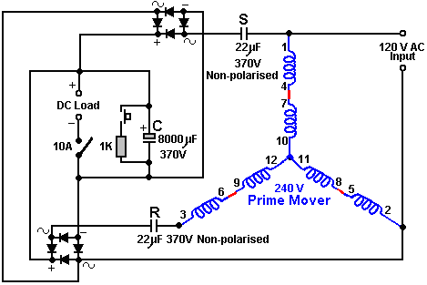
Phil
Wood, another member of the EVGRAY enthusiast Group, who has many
years of experience working with all varieties of electric motor, has
come up with a very clever circuit variation for the RotoVerter system.
His design has a 240 volt Prime Mover motor driven with 240 volt
AC. The revised circuit now has automated start-up and it
provides an extra DC output which can be used to power additional
equipment. His circuit is shown here:

Phil specifies
the diode bridges as 20 amp 400 volt and the output capacitor as 4000 to
8000 microfarads 370 volt working. The ON/OFF switch on the DC
output should be 10 amp 250 volt AC working. The circuit operates
as follows:
The charge capacitor “C” needs to be fully
discharged before the motor is started, so the press-button switch is
pressed to connect the 1K resistor across the capacitor to discharge it
fully. If you prefer, the press-button switch and resistor can be
omitted and the switch to the DC load closed before the AC input is
applied. The switch must then be opened and the AC connected.
The starting capacitor “S” and capacitor “R” both operate at full
potential until capacitor “C” begins to charge. As capacitor “C”
goes through its charging phase, the resistance to capacitors “R” and
“S” increases and their potential capacitance becomes less,
automatically following the capacitance curve required for proper AC
motor operation at start-up.
After a few seconds of run time,
the output switch is operated, connecting the DC load. By varying
the resistance of the DC load, the correct tuning point can be found.
At that point, the DC load resistance keeps both of the
capacitors “R” and “S” operating at a potentially low capacitance value.
The operation of this circuit is unique, with all of the energy
which is normally wasted when the AC motor is starting, being collected
in the output capacitor “C”. The other bonus is where a DC load
is powered for free while it keeps capacitors “R” and “S” in their
optimum operating state. The DC load resistance needs to be
adjusted to find the value which allows automatic operation of the
circuit. When that value has been found and made a permanent part
of the installation, then the switch can be left on when the motor is
started (which means that it can be omitted). If the switch is
left on through the starting phase, capacitor “C” can be a lower value
if the DC load resistance is high enough to allow the capacitor to go
through its phase shift.
The capacitor values shown above were
those found to work well with Phil’s test motor which was a
three-winding, 5 horsepower, 240 volt unit. Under test, driving a
fan, the motor draws a maximum of 117 watts and a variable speed 600
watt drill was used for the DC load. The motor operates at its
full potential with this circuit.
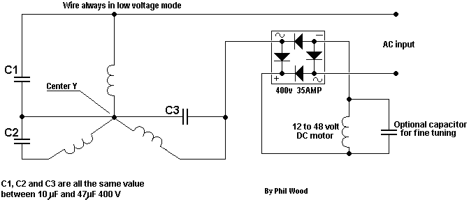
------------------------
The circuit will need
different capacitors for operation with a 120 Volt AC supply. The
actual values are best determined by testing with the motor which is to
be used, but the following diagram is a realistic starting point:
The 120 V AC
motor runs very smoothly and quietly drawing only 20 watts of input
power.
Advancing the design even further, Phil has now
produced an extremely clever design by introducing an additional DC
motor/generator coupled to the “Prime Mover” motor. The coupling
is nominally mechanical with the two motors physically linked together
with a belt and pulleys, but the electrical linking is such that the two
motors will synchronise automatically if the mechanical linkage is
omitted. I should like to express my thanks to him for sharing
this information, diagrams and photographs freely.
This circuit
is very clever as the DC motor/generator automatically adjusts the
running of the AC motor both at startup and under varying loading.
Also, the selection of the capacitors is not so critical and no
manual intervention is needed at startup. In addition, the DC
motor/generator can be used as an additional source of electricity.
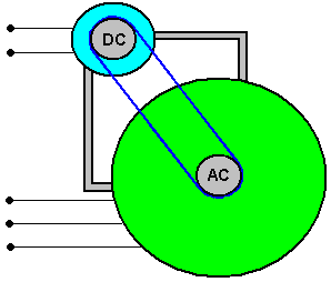
Phil’s setup
As the loading on the Prime
Mover motor is quite low due to the very, very high efficiency of the
RotoVerter arrangement, it is perfectly feasible to drive the whole
system with a low-power inverter run from a battery. If that is
done, then it is possible to use two batteries. One is charged by
the DC generator while the other is driving the inverter. A timer
circuit then switches the batteries over on a regular basis using relay
switching.
Extra Energy Collection
A very
effective additional circuit has been developed by David Kousoulides.
This circuit allows extra current to be drawn off a RotoVerter
while it is running, without increasing the input power needed to drive
the RotoVerter. David’s circuit can be used with a wide range of
systems, but here it is being shown as an addition to the RotoVerter
system, raising it’s efficiency even higher than before.
As is
common with many effective circuits, it is basically very simple
looking, and it’s apparent operation is easily explained. The
objective is to draw additional current from the RotoVerter and use that
current to charge one or more batteries, without loading the RotoVerter
at all. The current take off is in the form of a rapid series of
current pulses which can be heard as a series of faint clicks when fed
into the battery.
Let us examine the circuit section by section:
First, we start with a standard “off the shelf” 3-phase motor.
In this example, the motor is a 7.5 horsepower motor, which when
wired in RotoVerter mode, using just a single-phase supply as shown
here, only draws a very low amount of power when running, especially if
the single-phase supply is about 25% of the voltage rating of the motor:
Because the
running power draw is so low, it is possible to run this motor from a
standard battery-powered inverter, but the current draw at start-up is
some 17 amps, so the mains is used to get the motor started and then the
motor is switched from the mains to the inverter. The inverter
also allows easy measurement of the power input and so makes for easier
calculation of the overall power efficiency of the system.
There
is a power extraction device called a “diode-plug”, which in spite of
it’s seeming simplicity, is actually much more subtle in it’s operation
than would appear from a quick glance at the circuit:
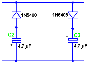
This circuit
has been presented as a public-domain non-copyrightable circuit by
Hector Perez Torres and it is capable of extracting power from a range
of different systems, without affecting those systems or increasing
their power draw. In the circuit presented below, just the first
half of the diode plug is utilised, though it should perhaps be stressed
that it would be perfectly feasible to raise the efficiency of the
circuit even further by adding extra components to duplicate the power
feed from the battery, drawing on both parts of the diode-plug circuit.
For clarity, this is not shown here, but it should be understood
that it is a possible, and indeed desirable, extension to the circuitry
described here.
When the motor is running, high voltages are
developed across the windings of the motor. As only the first
half of the diode-plug is being shown here, we will be capturing and
using the negative-going voltages. These negative-going pulses
are picked up, stored in a capacitor and used to charge a battery using
the following circuit:
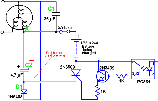
Here we have
the same RotoVerter circuit as before, with high voltage being developed
across capacitor C1. The battery-charging section is a
free-floating circuit connected to point A of the motor. The
high-voltage diode D1 is used to feed negative-going pulses to capacitor
C2 which causes a large charge to build up in that capacitor. At
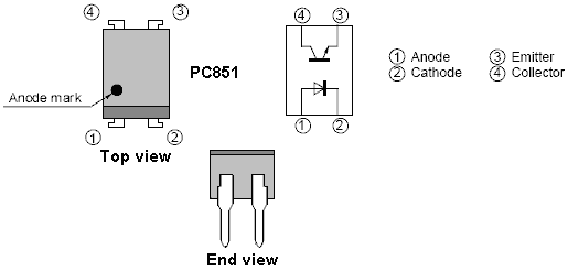
the appropriate moment, the PC851 opto-isolator is triggered.
This feeds a current into the base of the 2N3439 transistor, switching
it on and firing the 2N6509 thyristor. This effectively switches
capacitor C2 across the battery, which discharges the capacitor into the
battery. This feeds a substantial charging power pulse into the
battery. As the capacitor voltage drops, the thyristor is starved
of current and it turns off automatically. The charging sequence
for the capacitor starts again with the next pulse from the windings of
the motor.
The only other thing to be arranged is the triggering
of the opto-isolator. This should be done at the peak of a
positive voltage on the motor windings and has been built like this:
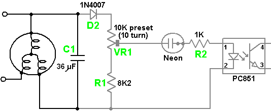
Here, we have
the RotoVerter motor as before, with the voltage developed on C1 being
used to trigger the opto-isolator at the appropriate moment. The
voltage on C1 is sensed by the diode D2, the pre-set resistor VR1 and
the resistor R1. These place a load of some 18.2K ohms on
capacitor C1 as the neon has a very high resistance when not conducting.
The ten-turn preset resistor is adjusted to make the neon fire at
the peak of the voltage wave coming from the motor. although the
adjustment screw of most preset resistors is fully isolated from the
resistor, it is recommended that adjustment of the screw be done using
an insulated main-tester type of screwdriver, or a solid plastic
trimmer-core adjustment tool.
The circuit to test one half of
the diode plug is then:
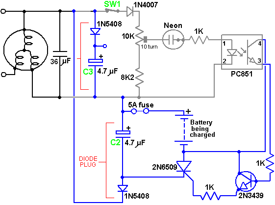
The switch
SW1 is included so that the charging section can be switched off at any
time and this switch should not be closed until the motor gets up to
speed. All wire connections should be made before power is
applied to the circuit. Capacitor C1 which is shown as 36
microfarads, has a value which is optimised for the particular motor
being used and will normally be in the range 17 to 24 microfarads for a
well-prepared motor. The motor used for this development was
retrieved from a scrapyard and was not prepared in any way.
The
value of capacitor C2 can be increased by experimenting to find at what
value the resonance gets killed and the charging section starts drawing
extra current from the supply. It should be noted that many new
thyristors (Silicon Controlled Rectifiers or “SCR”s) are faulty when
supplied (sometimes as many as half of those supplied can be faulty). It
is therefore important to test the thyristor to be used in this circuit
before installing it. The circuit shown below can be used for the
testing, but it should be stressed that even if the component passes the
test, that does not guarantee that it will work reliably in the circuit.
For example, while 2N6509 thyristors are generally satisfactory,
it has been found that C126D types are not. A thyristor passing
the test may still operate unpredictably with false triggers.
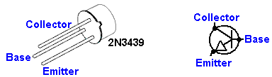
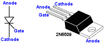
Please note
that the 2N6509 package has the Anode connected inside the housing to
the metal mounting tab.
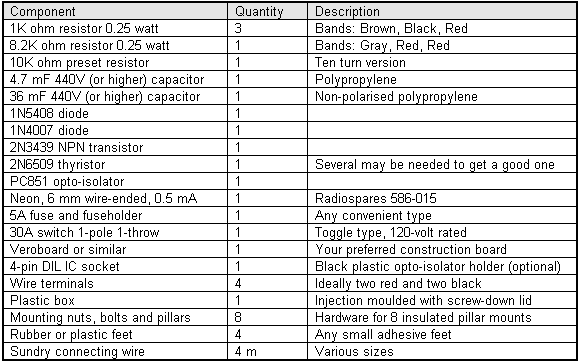
Components List:
When using and testing this
circuit, it is important that all wires are connected securely in place
before the motor is started. This is because high voltages are
generated and creating sparks when making connections does not do any of
the components any particular good. If the circuit is to be
turned off while the motor is still running, then switch SW1 is there
for just that purpose.
The operating technique is as
follows:
Before starting the motor, adjust the slider of
the preset resistor VR1 to the fixed resistor end of it’s track.
This ensures that the charging circuit will not operate as the neon will
not fire. Power up the circuit and start adjusting the preset
resistor very slowly until the neon starts to flash occasionally.
There should be no increased load on the motor and so no extra current
drawn from the input supply.
If there is an increase in the
load, you will be able to tell by the speed of the motor and the sound
it makes. If there is an increase in the load, then back off VR1
and check the circuit construction. If there is no increased
load, then continue turning VR1 slowly until a position is reached where
the neon remains lit all the time. You should see the voltage
across the battery being charged increase without any loading effects on
the motor.
If you use an oscilloscope on this circuit, please
remember that there is no “ground” reference voltage and that the
circuit is not isolated.
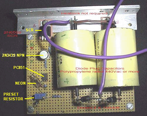
Here is a picture of David’s actual
board construction. There are various ways for building any
circuit. This particular construction method uses plain matrix
board to hold the components in position and the bulk of the
interconnections are made underneath the board. The
charge-collecting capacitor is made here from two separate polypropolene
440 volt capacitors wired in parallel. David has opted to use a
separate diode on each capacitor as this has the effect of doubling the
current-carrying capacity of a single diode and is a popular technique
in pulse charge circuits where sometimes several diodes are wired in
parallel.
David has included a heatsink, which he marks as being
“not required” but you will notice that there is insulation between the
SCR and the heatsink. Mica “washers” available from the suppliers
of semiconductors are particularly good for this, as mica is a good
insulator and it also conducts heat very well.
Thyristor
testing:
The components needed to construct the thyristor
testing circuit shown below can be bought as Kit number 1087 from
www.QuasarElectronics.com
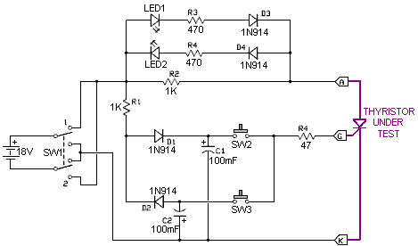
The circuit
is operated by operating SW1 several times so as to get capacitors C1
and C2 fully charged. LED1 and LED2 should both be off. If either
of them light, then the thyristor is faulty.
Next, with SW1 at
it’s position 1, press switch SW2 briefly. LED1 should light and
stay on after SW2 is released. If either of these two things does
not happen, then the thyristor is faulty.
With LED1 lit, press
SW3 and LED1 should go out. If that does not happen, then the
thyristor is faulty.
As mentioned before, even if the thyristor
passes these tests it does not guarantee that it will work correctly in
any circuit as it may operate intermittently and it may trigger
spuriously when it shouldn’t.
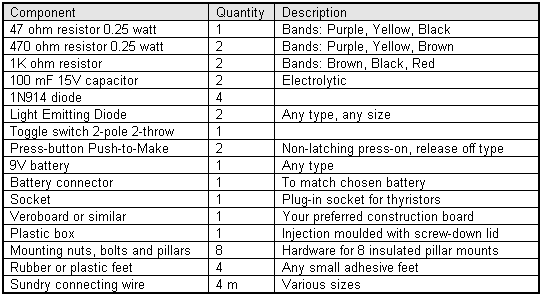
Phil Wood has
developed a particularly effective method for extracting the excess
resonant circulating energy of a RotoVerter Prime Mover. This is
the circuit:
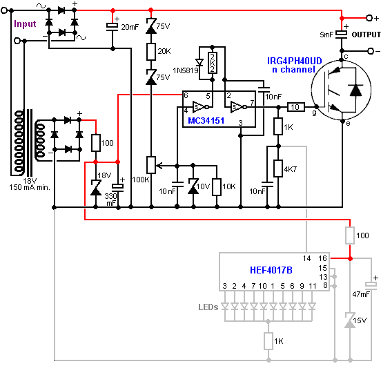
Care needs to
be taken when constructing this circuit. For example, the circuit
performance is displayed by an HEF4017B 5-stage Johnson counter, but for
some lunatic reason, the 4017 designation is also used for a completely
different chip of the same size and number of DIL pins, namely the “CMOS
high-speed hex flip-flop with Reset”, an action definitely worthy of a
stupidity award. Another point to watch out for is that the 1A
1N5819 diode is a very high-speed Schottky barrier component.
The circuit operation is as follows:
The input from the
RotoVertor motor is stepped-down by a transformer to give an 18-volt
(nominal) AC output, which is then rectified by a standard rectifier
bridge and the output smoothed by an 18-volt zener diode and a 330mF
smoothing capacitor, and used to power the MC34151 chip. This DC
power supply line is further dropped and stabilised by a 15-volt zener
diode and a 47mF capacitor and used to power the LED display chip
HEF4017B.
The raw RotoVerter input is also taken direct and
rectified by a second 400-volt 35-amp rectifier diode bridge and
smoothed by a 20mF capacitor with a high voltage rating. It must
be understood that the RotoVerter system is liable to produce
considerable power surges from time to time and so this circuit must be
capable of handling and benefiting from these surges. This is why
the IRG4PH40UD IGBT device was selected (apart from it’s very reasonable
price) as it robust and can handle high voltages.
The resulting
high-voltage DC is taken by the chain of components two 75-volt zener
diodes, 20K resistor and the 100K variable resistor. The voltage
developed on the slider of this variable resistor is loaded with a 10K
resistor and voltage-limited with a 10-volt zener diode, and decoupled
with a 10nF capacitor before being passed to the MC34151 high-speed
MOSFET dual driver chip. Both of these drivers are used to
sharpen up the pulse and drive the IGBT cleanly. The result is an
output which is a series of DC pulses. The operation of the
circuit can be seen quite clearly, thanks to the HEF4017B display
circuit which drives a row of LEDs, triggered by the IGBT gate signal,
divided by the 1K / 4.7K voltage divider decoupled by the 10nF
capacitor. This display shows clearly when the IGBT is switching
correctly - actually, the display circuit is quite a useful device for
people who do not own an oscilloscope, not just for this circuit, but a
wide range of different circuits.
The physical board layout for
Phil’s circuit is shown here:
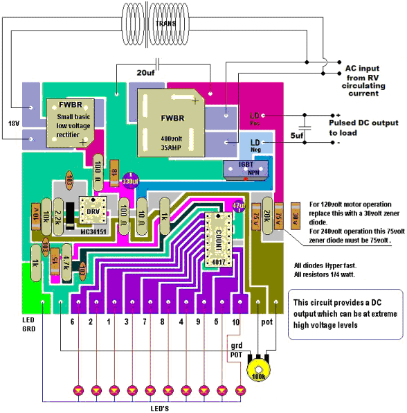
As you will
notice from the notes on Phil’s board layout shown above, the first of
the 75-volt zener diodes used on the direct RotoVerter power feed,
should be replaced with a 30-volt zener if a 120-volt motor is used in
this circuit.
Another important point which needs to be
stressed, is that the pulsed DC output from this circuit can be at
extremely high voltages and needs to treated with considerable care.
This is not a circuit for beginners and anyone who is not
familiar with handling high voltages needs the supervision of an
experienced person. Also, if either this circuit or the
RotoVerter is connected to the mains, then no scope ground leads should
be connected as the circuit can be a hundred volts or more below ground
potential.
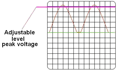
The pattern
of the printed-circuit board when viewed from the underside of the board
is shown here:
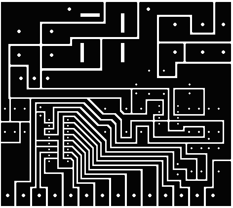
And component
packaging is:
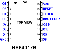
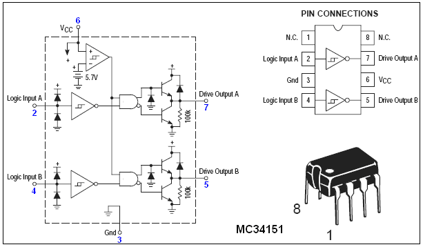
Phil’s build
of his circuit was implemented like this:
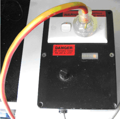
Component List:
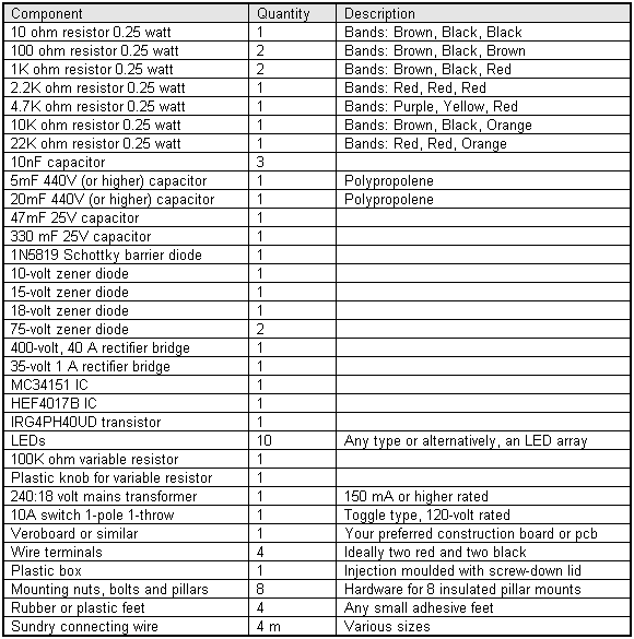
Lawrence
Tseung. Lawrence has been presenting his theory of lead-out
energy which indicates that excess energy is drawn from the environment
when there is an impact. The method of producing this effect which he
has followed is to create an unbalanced wheel and demonstrate that
excess energy is produced. It should be stressed that energy is never
created or destroyed and so, when he measures more energy in his device
than the energy which he uses to power it, energy is not being created
but is instead, being drawn in from the local environment. Lawrence has
recently demonstrated a prototype to members of the public:
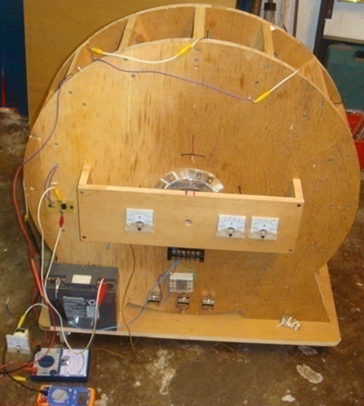
This simple
device was demonstrated to have 3.3 times as much output power as the
input power needed to make it operate. This is an early prototype which
was demonstrated in October 2009 and Lawrence and his helpers are
working on to produce more advanced models which have kilowatts of
excess electrical power.
Mr Tseung remarks: "The Lee-Tseung
Lead-Out Energy Theory was first disclosed to the world on 20th
December 2004 at Tai Po, in Hong Kong. The Lead-Out Energy Theory
basically says that one can lead-out (or bring-in) Energy from the
surrounding environment into a Lead-Out Energy Machine. The total Input
energy is equal to the sum of the Supplied Energy plus the Lead-Out
Energy. For example, if the supplied energy is 100 units and the
lead-out energy is 50 units, the device's total Input Energy will be 150
units. This means that the Output Energy can be more than the Supplied
Energy of 100 units provided by the person using the device.
If
we ignore the small loss of energy caused by less than 100% efficiency
of the device itself, then the Output Energy will be the whole of the
150 units. If we use 50 of the output energy units and feed back 100 of
the output units as the Supplied Energy, then that Supplied Energy can
again lead-out another 50 units of excess output Energy for us to use.
Thus a Lead-Out Energy Machine can continuously lead-out pollution-free,
virtually inexhaustible and readily available energy for us to use. We
do not need to burn any fossil fuel or pollute our environment. The two
examples of Lead-Out energy which we access are Gravitational and
Electron-Motion energy.
The Lead-Out Energy theory does not
violate the Law of Conservation of Energy. The Law of Conservation of
Energy has been used as a roadblock for the so called “Overunity”
devices. The patent offices and the scientific establishment routinely
dismiss an invention as belonging to the impossible “perpetual-motion
machine” category if the inventor cannot identify the energy source of
his invention.
We got the help of Mr. Tong Po Chi to produce a
60 cm diameter Lead-Out Energy machine in October 2009. The Output
Energy of that device is greater than the Input Energy by a factor of 3
times. These results are confirmed by voltmeters and ammeters measuring
the Input and Output energies.
The Tong wheel has been shown at
two Open Shows in Hong Kong (Inno Carnival 2009 and Inno Design Tech
Expo) in November and December 2009. Over 25,000 people have seen it.
The Better Hong Kong Radio Show has video recorded it, the discussions
being conducted in Chinese. At this time, the Tong wheel is at the Radio
Studio available for experts to view and examine with their own
instruments."
The Tong wheel has a diameter of 600 mm, 16
permanent magnets mounted on its rim and 15 air-core coils mounted
around it on the stator. There is one position sensor. The coils can be
switched to act as drive coils or as energy collection coils:
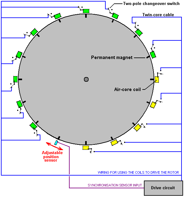
With this arrangement, if the positions the
switches as shown for ten of the fifteen coils shown here, then they act
as drive coils. The sensor is adjusted so that the drive circuit
delivers a brief energising pulse to those coils just after the magnets
have passed their exact alignment position with the coils. This causes
them to generate a magnetic field which repels the magnets, thrusting
the rotor around.
The pulse is very brief, so very little power
is needed to accomplish this pulsing. As mentioned before, any number of
coils can be switched to provide this driving force. With this
particular wheel construction by Mr Tong, the best number has been found
to be ten drive coils.
The power pick-up is achieved by
gathering the electricity generated in some of the coils as the magnets
move past them:
In this particular arrangement, five of the
coils gather energy while ten provide the drive. For the sake of
simplicity, the diagram shows the five collection coils adjacent to each
other and while that would work, the wheel is better balanced if the
drive coils are evenly spaced out around the rim. For that reason, this
switching would actually be selected to give five sets of two drive
coils followed by one pick-up coil as that gives a perfectly balanced
thrust on the wheel.
The two diagrams above are shown separately
in order to make it clear how the drive switching and the power pick-up
switching are arranged. The full design arrangement and the balanced
switching are shown in the following diagram which indicates how the
full design is implemented on this particular implementation of the
wheel design. The sensor can be a coil feeding a semiconductor switching
circuit, or it can be a magnetic semiconductor called a Hall-effect
device which can also feed a semiconductor circuit. An alternative would
be a reed switch which is a simple mechanical switch encased in an inert
gas inside a tiny glass envelope. Suitable switching circuits are
described and explained in chapter 12 of this eBook.
Mr Tseung remarks that the large wheel size is
due to the fact that the Pulse Force takes time to impart the impulse to
the wheel and lead-out energy from the environment into the system. If
you want to see this actual wheel, you can email Dr. Alexandra Yuan at
ayuan@hkstar.com to make an appointment. The Tong wheel is located at
the Better Hong Kong Radio Studio in Causeway Bay, Hong Kong. Just say
that you want to see the Lead-Out Energy Machine. The demonstration can
be in English or in Chinese. Ideally, there should be a group of at
least six visitors with one or more being a qualified engineer or
scientist, and you are welcome to bring your own cameras and/or test
equipment. It is planned to produce a version which has a 300 watt
output, and another with a 5 kilowatt output. Educational kits are also
planned.
If you decide to replicate this particular design, then
to raise the output power level you might consider putting another set
of coils around the wheel and either using them as fifteen additional
energy pick-up coils or alternatively, pulsing the wheel twice as often.
Adding one or more additional rotor discs to the same rotating shaft is
also an option and that has the advantage of increasing the rotor weight
and improving the effect of the impulses on the rotor.
The
diameter of the wire used to wind the coils is a design choice which has
a wide scope. The thicker the wire, the greater the current and the
larger the impulse given to the wheel. The coils are normally connected
in parallel as shown in the diagrams.
Because of the way
magnetic field strength drops off with the square of the distance, it is
generally considered good design practice to make the coils one and a
half times as wide as they are deep, as indicated in the diagrams above.
*****************
It is felt that some specific
information on alternators would be helpful at this point. My thanks
goes to Professor Kevin R. Sullivan, Professor of Automotive Technology,
Skyline College, San Bruno, California, who has given his kind
permission for the reproduction of the following training material from
his excellent web site at http://www.autoshop101.com/ which
I recommend that you visit. The following material is his copyright and
All Rights are Reserved by Professor Sullivan.
UNDERSTANDING THE ALTERNATOR
The Charging
System:
A vehicle
charging system has three major components: the Battery, the Alternator,
and the Regulator. The alternator works together with the battery to
supply power when the vehicle is running. The output of an alternator is
direct current (DC), however the alternator actually creates AC voltage
which is then converted to DC as it leaves the alternator on its way to
charge the battery and power the other electrical loads.
The Charging System Circuit:
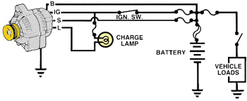
Four wires
connect the alternator to the rest of the charging system:
'B' is the alternator output wire that supplies current
to the battery.
'IG' is the ignition input that turns on the
alternator/regulator assembly.
'S' is used by the regulator to
monitor charging voltage at the battery.
'L' is the wire the
regulator uses to ground the charge warning
lamp.
Alternator Terminal ID's:
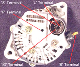
'S'
terminal: Senses the battery voltage
'IG' terminal: Ignition
switch signal turns regulator ON
'L' terminal: Grounds warning
lamp
'B' terminal: Alternator output terminal
'F'
terminal: Regulator Full-Field bypass
The Alternator
Assembly:
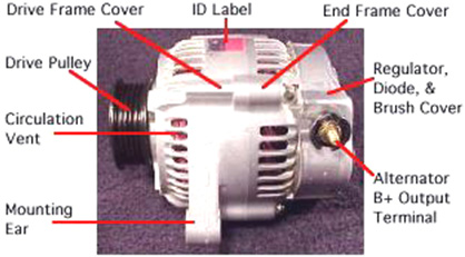
Alternator
Overview:
The alternator contains:
A rotating field
winding called the rotor.
A stationary induction winding called
the stator.
A diode assembly called the rectifier bridge.
A control device called the voltage regulator.
Two
internal fans to promote air circulation
Alternator
Design:
Most
regulators are on the inside of the alternator. Older models have
externally mounted regulators.
Unlike other models, this model
can be easily serviced from the rear of the unit. The rear cover can be
removed to expose internal parts.
However, today's practice is
to replace the alternator as a unit, should one of it's internal
components fail.
Drive Pulley:
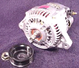
Alternator
drive pulleys either bolt on or are pressed on the rotor shaft. Both 'V'
and Multi-groove types are used. Please note this alternator does not
have an external fan as part of the pulley assembly.
While many
manufacturers do use a external fan for cooling. This alternator has two
internal fans to draw air in for cooling.
Inside the
Alternator:
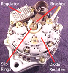
Removal of
the rear cover reveals:
The Regulator which controls the
output of the alternator.
The Brushes which conduct
current to the rotor field winding.
The Rectifier Bridge
which converts the generated AC voltage to a DC voltage.
The
Slip Rings (part of the rotor assembly) which are connected to each
end of the field winding.
Brushes:
Two slip
rings are located on one end of the rotor assembly. Each end of the
rotor field winding is attached to a slip ring. This, allows current to
flow through the field winding.
Two
stationary carbon brushes ride on the two rotating slip rings. These
bushes are either soldered or bolted in position.
Electronic IC Regulator:
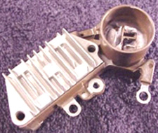
The regulator
is the brain of the charging system. It monitors both the battery
voltage and the stator voltage and, depending on the measured voltages,
it adjusts the amount of rotor field current so as to control the output
of the alternator.
Regulators can be mounted in an internal or
an external position. Nowadays, most alternators have a regulator which
is mounted internally.
Diode Rectifier:
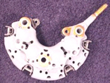
The Diode
Rectifier Bridge is responsible for the conversion or rectification
of AC voltage to DC voltage.
Six or eight diodes are used to
rectify the AC stator voltage to DC voltage. Half of these diodes are
used on the positive side and the other half on the negative side.
Inside the Alternator:
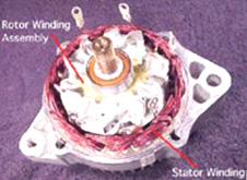
Opening the
case reveals:
The rotor winding assembly which rotates
inside the stator winding. The rotor generates a magnetic field and the
stator winding develops voltage, which causes current to flow
from the induced magnetic field of the rotor.
The Rotor
Assembly:
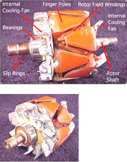
A basic rotor
consists of an iron core, a coil winding, two slip rings,
and two claw-shaped finger pole pieces. Some models have support
bearings and one or two internal cooling fans.
The rotor is
driven or rotated inside the alternator by an engine (alternator) drive
belt.
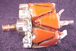
The rotor
contains the field winding wound over an iron core which is part of the
shaft. Surrounding the field coil are two claw-type finger poles. Each
end of the rotor field winding is attached to a slip ring. Stationary
brushes connect the alternator to the rotor. The rotor assembly is
supported by bearings. One on the shaft and the other in the drive
frame.
Alternating Magnetic Field:
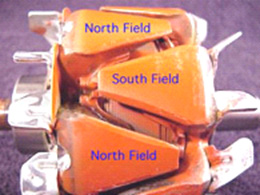
The rotor
field winding creates the magnetic field that induces voltage in the
stator. The magnetic field saturates the iron finger poles. One finger
pole becomes a North pole and the other a South pole.
The rotor
spins creating an alternating magnetic field, North, South, North,
South, etc.
Stator Winding:
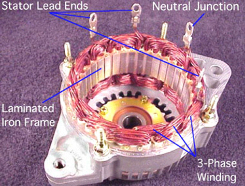
The stator
winding looks like the picture above.
Rotor / Stator
Relationship:
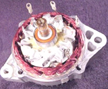
As the rotor
assembly rotates within the stator winding: The alternating magnetic
field from the spinning rotor induces an alternating voltage into the
stator winding. The strength of the magnetic field and the speed of the
rotor affect the amount of voltage induced in the stator.
Stator Windings:
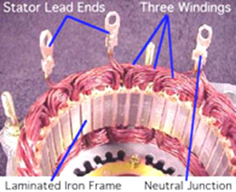
The stator is
made with three sets of windings. Each winding is placed is a different
position compared with the others. A laminated iron frame concentrates
the magnetic field. Stator lead ends output current to the diode
rectifier bridge.
The Neutral Junction in the Wye design can be
identified by the 6 strands of wire.
3-Phase Windings
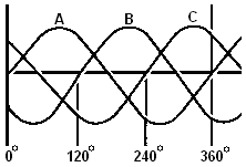
The stator
winding has three sets of windings. Each winding is formed into a number
of evenly spaced coils around the stator core.
The result is
three overlapping single-phase AC sine-wave current peaks, A, B, C.
These waves add together to make up the total AC output of the
stator. This is called three-phase current.
Three-phase current
provides a more even current output than a single-phase output would do.
Stator Designs:
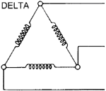
Delta-wound
stators can be identified by having only three stator leads, and each
lead will have the same number of wires attached.
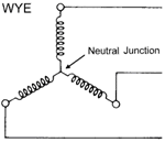
Wye-style
stators have four leads. One of the leads is called the Neutral
Junction. The Neutral Junction is common to all the other leads.
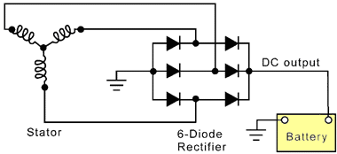
Wye-wound
stators have three windings with a common neutral junction. They can be
identified because they have 4 stator lead ends. Wye wound stators are
used in alternators that require high-voltage output at low alternator
speeds. Two windings are in series at any one time during charge output.
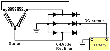
Delta-wound
stators can be identified because they have only three stator lead ends.
Delta stators allow for higher current flow being delivered at low RPM.
The windings are in parallel rather than in series as the Wye designs
have.
Diode Rectifier Bridge Assembly:
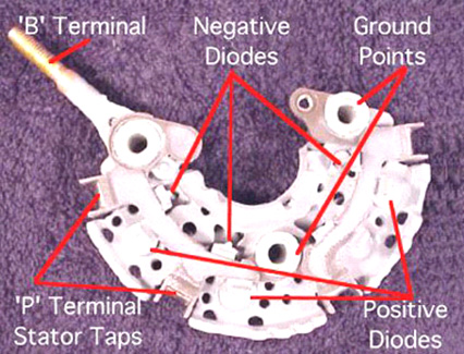
Rectifier
Operation:

Two diodes
are connected to each stator lead. One positive the other negative.
Because a single diode will only block half of the AC voltage, six or
eight diodes are used to rectify the AC stator voltage to DC voltage.
Diodes used in this configuration will redirect both the
positive and negative parts of the AC voltage in order to produce a
better DC voltage waveform. This process is called 'Full - Wave
Rectification'.
Diodes:
Diodes are
used as one-way electrical check valves. They pass current in only one
direction, and never in the other direction. Diodes are mounted in a
heat sink to dissipate the heat generated by the current flow. Diodes
redirect the AC voltage and convert it into DC voltage, so the battery
receives the correct polarity.
Rectifier Operation:
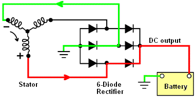
The red path
is the positive current passing through the rectifier as it goes to the
positive battery terminal. The path shown in green completes the
circuit.
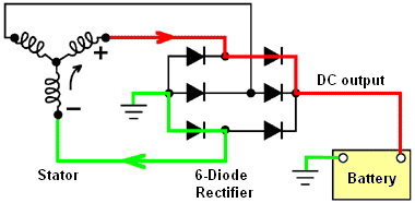
As the rotor
continues its movement, the voltages generated in the three windings,
change in polarity. The battery is still fed current, but now a
different winding feeds it. Again, the red path shows the current flow
to the battery and the green path shows how the circuit is completed.
The same charging continues even though different windings and diodes
are being used.
Electronic Regulator:
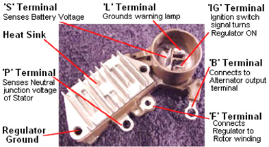
The regulator
attempts to maintain a set charging voltage. If the charging voltage
falls below this point, the regulator increases the field current, which
strengthens the magnetic field, resulting in a raising of the alternator
output voltage.
If the charging voltage rises above this point,
the regulator decreases the field current , thus weakening the magnetic
field, producing a lowering of the alternator output voltage.
Regulator Types:
Two regulator designs can be
used. The first type is:
The Grounded Regulator type.
This type of regulator controls the amount of current flowing through
the battery ground (negative) into the field winding in the rotor:
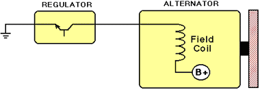
The second
type is:
The Grounded Field type. This type of regulator
controls the amount of current flowing from the Battery Positive (‘B+’)
into the field winding in the rotor.
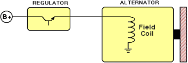
The
Working Alternator:
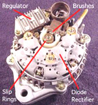
The
regulator monitors battery voltage and controls current flow to
the rotor assembly.
The rotor produces a magnetic field.
Voltage is induced in the stator windings.
The
rectifier bridge converts the AC stator voltage to DC output
voltage for use by the vehicle.
**********************
This website
has the following very interesting information from an unknown American
author:
INTRODUCTION
Since 1980, alternators have
replaced generators in motor vehicles. The reasons are many: output
current can be produced at lower rpm, voltage can be more accurately
controlled with solid state regulators, alternators need less
maintenance, and they cost less to manufacture.
When modified,
auto alternators can provide variable direct current at 0 to 120 volts
for battery charging, hot charging, light arc welding, or for running
AC-DC appliances and lights. Another simple modification provides AC
power to run some transformer-operated appliances. If you know the
secrets of its operation and the modifications possible, the small
low-cost alternator can become a versatile power plant.
BASIC
CONSTRUCTION
The old-fashioned generator contains a wound stator
which produces a constant magnetic field in which a revolving coil of
wire, called an armature, turns. A commutator on one end of the armature
made up of many individual brass segments passes the generated current
to the outside world through carbon brushes.

Because
commutator segments must be electrically insulated from one another,
they can not be fabricated from a single block of metal. Each commutator
segment must be individually attached to the armature shaft. This is a
source of mechanical weakness. When the armature is rotated at high rpm,
centrifugal force can cause the commutator to explode, throwing segments
in all directions.
To prevent explosions, a generator is usually
driven at less than the engine speed. An vehicle engine may turn at
5,000 rpm, but the generator must be geared down to run at a maximum of
2,500 rpm for safety's sake. As a result, the generator turns so slowly
at low engine rpm that it produces little or no current.
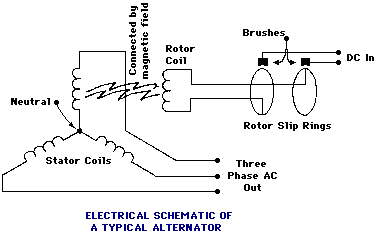
Like the
generator, a modern alternator contains both moving and stationary coils
of wire. However, in the alternator, the moving coil, called the rotor,
uses current supplied through slip rings to generate a moving magnetic
field. Power is extracted from the stationary field coils.
Slip
rings replace the weak generator commutator. The rotor coils themselves
are encased in a strong soft iron shell making the whole assembly much
stronger than the generator armature. The net result is that alternators
can be driven at much higher speeds without any danger of explosion. In
fact, alternators are usually driven at up to twice engine speed some
running at 8,000 rpm or more. At low engine rpm, the geared-up
alternator turns much faster than a comparable geared-down generator.
The net result is that the alternator can begin producing useful
charging current at lower engine rpm than the generator can.
A coil of wire
rotating in a magnetic field produces an alternating current with a
frequency dependent on how fast the coil turns, one cycle being produced
per revolution. A generator armature uses a commutator to mechanically
switch rotating windings in and out of automobile's electrical system to
produce direct current.
The three separate stationary windings
of the typical auto alternator produce three-phase alternating current.
Rather than use a commutator to mechanically convert AC to DC, the
alternator uses six diodes in a full-wave bridge rectifier circuit. In
essence the diodes are solid state switches with no moving parts, making
them maintenance-free and explosion proof.
The alternator output
voltage can be controlled or regulated by varying the rotor current.
Regulators sample the output voltage and automatically change the
intensity of the rotating magnetic field by adjusting the current fed to
the rotor through the slip rings. The adjustments are made in such a way
so as to bring the output voltage to the desired level.
THREE-PHASE POWER Surprisingly, alternators are
constructed with three sets of field windings positioned evenly at 120
degree intervals inside the frame. Such construction produces
three-phase AC. But why three-phase?
If we look at the effect of
diodes on a single-phase AC current, we see that the output is a series
of DC pulses. True direct current is completely smooth. The output of
the diodes (rectified AC) is bumpy , and so is said to possess ripple
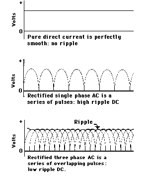
When the
rectified DC from each of the three-phase windings is added together or
superimposed, the peaks overlap to produce a much cleaner DC with much
less ripple. Lead-acid batteries last longer when charged with pure DC
than high ripple rectified DC. Generators may be a mechanical and
electrical nightmare, but they put out very clean DC. Three-phase
windings were designed into alternators to produce DC of greater purity.
Many alternators connect one lead of each winding to a common
point called a neutral. The other lead of each winding is connected to a
pair of diodes. Three windings, each using two diodes, accounts for the
six diodes found on most alternators.
Newer alternators,
particularly high current models, use two additional diodes on the
neutral connection, to provide a sample of the alternator output voltage
which is then used by the regulator.
In the future, internal
mechanical construction, electrical circuits, regulator operation and
physical location will probably change somewhat but basic alternator
theory will not change. The exact details for the alternator you have
can usually be found in a standard vehicle repair manual such as Motor's
or Chilton's. Often you will get instructions on dismantling and
repairing alternators as well.
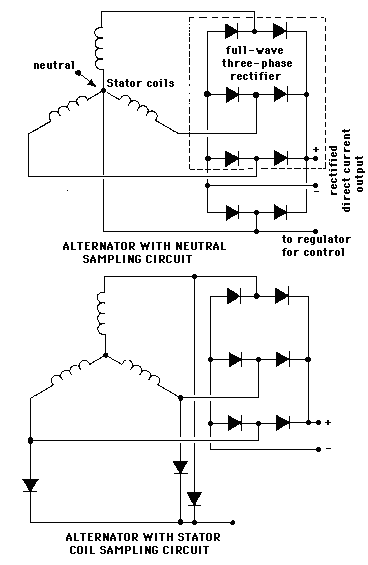
The diagrams
shown here are general and should apply to all alternators.
REGULATORS
Early alternators used relays to
regulate their output voltage much like those used on generators. When
cheaper, more reliable, solid-state devices became available, electronic
regulators became standard.
Although most regulators are factory
set to force an alternator to produce 12 to 14 volts, they can be
modified or new regulators custom built to provide almost any voltage up
to 130 volts once their operation is understood.
If we were to
run an alternator at some fixed rpm, we would find that changing the
intensity of the rotating magnetic field would change the output voltage
of the alternator. We can change that magnetic field by changing the
amount of current flowing through the slip rings into the rotor. Since
the resistance of the rotor windings is constant, merely changing the
input voltage to the rotor will change the current flowing into the
rotor by a proportionate amount.
Suppose we have
alternator-spinning at 2,000 rpm. We have it attached to some electrical
load drawing, say, 10 amps at 12 volts. Let's assume that the rotor is
using 1 amp at 4 volts. Suppose we increase the electrical load: so that
we now need 15 amps. Due to internal electrical resistance of the whole
system, the voltage falls to 11 volts. To get the output voltage back up
to 12 volts we must increase the rotor magnetic field intensity. So we
adjust the rotor voltage up to 6 volts and in doing so, we find the
rotor is now drawing 1.5 amps of current. This increased current results
in an increased magnetic field which at 2,000 rpm gives an output of 15
amps at 12 volts. It is the job of the regulator to make these
adjustments quickly and automatically.
Let's suppose that we set
the rotor current at its maximum value, say 3 amps at 12 volts, and then
we vary the rpm. At low rpm, the output voltage might be only five
volts. As the rpm increases, the output voltage would hit 12 volts then
25, then 50, and at top end, over 100 volts. Alternators can sometimes
put out 140 volts when driven at their top rpm.
As you can
imagine, when the alternator is running at low rpm, the alternator is
putting maximum voltage and current into the rotor so that the
alternator output voltage will come up to 12 volts. When the rpm starts
to pick up so that the voltage starts to climb above 12, the regulator
starts cutting back the voltage and current into the rotor. At very high
rpm, the regulator is supplying the rotor with very little current, so
that the output voltage remains at a constant 12 volts.
An
electronic regulator provides continuous and instantaneous adjustment of
rotor current by sampling the alternator output voltage and by comparing
it to it's own internal standard reference voltage. In the following
circuit diagram, when output falls, a small current is sent to
transistor B which amplifies it
and sends it to transistor A
which acts as a valve in controlling the heavy current flow from the
battery to the rotor.
Input voltage to the regulator is usually
a steady 12 volts whereas output to the rotor varies from zero to 12
volts to control rotor current. Many rotors have a winding resistance of
about 3 or 4 ohms, which causes a current of 3 to 4 amps to flow at 12
volts (calculated with Ohm's law)
Suppose that to get 12 volts
out of an alternator we need to pump 2 amps of Direct Current into the
alternator's rotor which has an internal resistance of 3 ohms. What
would the rotor voltage have to be? We can calculate it with Ohm's law
which says Volts = Amps x Ohms, so in our example Volts = 2 amps x 3 ohms, or
Voltage = 6 volts
The regulator passes 2 amps but has to eat up the difference
between supply voltage, 12 volts, and rotor voltage, 6 volts - an excess
of 6 volts. How much power is this? We can do another simple
calculation: Watts = Amps x Volts, so
Watts = 2 amps rotor current x 6 volts difference = 12 watts
This 12 watts of power is turned into heat, and if the regulator
is to be kept cool and working properly, it must have heat-dissipating
fins or should be mounted on a large heat sink such as a Bumper (fender)
or firewall partition where this destructive heat can be carried away.
Regulators use Zener diodes to provide a stable reference
voltage. A voltage divider - the three resistors labelled C - extracts a
preset fraction of the voltage for comparison against the Zener. For
example, a regulator might have a 6 volt Zener in its circuit. To
provide a regulated 12 volts, the resistive voltage divider is set to
extract 1/2 of the sample voltage. When 12 volts is produced, half of
that 12 volts (six volts), is compared to the 6 volt Zener. If they are
equal, then no change is made to the rotor current. If the output
voltage falls to 8 volts, then the 6-volt Zener voltage is compared to
half of that 8 volts, (4 volts), and the regulator output current is
increased to compensate. If output rises above 12 volts, then the
regulator transistor is shut down enough to bring the output voltage
back down.
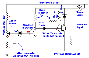
Electronic
regulators are superior to the old triple relay regulators used on
generators. Obviously, there are no contacts to burn. While the older
regulators would click in and out at the rate needed to hold output
fairly steady, while the solid-state regulators provide smooth quiet
service, causing small, continuous changes in rotor current. As long as
the electronic unit is kept cool, it should never need any servicing or
replacement of parts.
Alternator rotors are usually very rugged.
Specially shaped poles create multiple magnetic poles from a single
rotor winding. For instance, some Delco alternators have 8 alternating
pairs of poles folded back from either end. With a single revolution of
the rotor, the stator windings are hit with eight magnetic fields,
producing eight cycles of alternating current. This is probably done to
increase alternator output at very low rpm with limited rotor current.
At normal running speeds the frequency of the alternating current fed to
the diodes is usually several hundred cycles per second. HUNDREDS quite
unlike the 60 cycles per second which you get from a US mains socket.
Again, alternators are exceptionally strong allowing them to be
overdriven at high rpm. They will produce useable current at lower rpm,
and high voltage at high rpm if the rotor current is turned at maximum
speed. High frequency, three-phase AC, is fed to solid-state diodes to
produce a low ripple DC output.
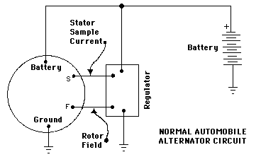
MODIFICATIONS
You'll
see ads in many magazines promoting a simple device which when added to
an vehicle alternator will allow you to get 3,000 watts of DC to run
AC-DC type appliances such as power drills, saws, and lights. This
so-called wonder has been sold at prices from a few dollars to more than
$25. You can build one for a couple dollars.
The secret of this
magical little box is extremely simple. A switch bypasses the regulator
putting 12 volts into the alternator rotor while transferring the
alternator output from the vehicle circuit to a mains socket installed
in the box. When the engine rpm increases, the voltage rises to 120
volts. The device, therefore is nothing more than a switch and a US
mains socket.
As we just discussed, alternator output voltage
increases as the revs go up. It is the job of the regulator to cut back
rotor current as the revs increase so that alternator output voltage
stays at a constant 12 to 14 volts. The switch in the wonder box
prevents the regulator from doing its job. As the revs increase so does
the alternator output voltage. Some of the more expensive boxes have a
volt meter to monitor the voltage being produced.
The diodes,
also called rectifiers, are solid-state devices which have low internal
resistance --- that is, they eat up very little of the current flowing
through them. These days solid-state diodes are easy to manufacture and
so they are low cost devices.
Diodes have two ratings: PIV and
amperage. The amperage rating tells you how much current the diode can
handle continuously. All diodes have some resistance, and at high
current levels some power is converted to heat by this resistance. The
ability to get rid of the waste heat determines how much current the
diode can handle. Remember, waste heat is determined by the current
flowing and it has nothing whatsoever to do with voltage.
The
PIV, "Peak Inverse Voltage" rating tells you how much voltage the diode
can withstand before its internal insulation breaks down. A diode rated
at 100 PIV can be used in circuits to 100 volts. A voltage of 200 volts
at a tiny fraction of an amp for even a thousandth of a second (a
voltage spike) can destroy the diode.
It's usually a good idea
to under-run diodes. If you want a diode to handle 10 amps at 100 volts,
then it would be wise to use a diode rated at 15 amps and 200 PIV.
Diodes used on modern alternators can usually handle the high voltage.
It is entirely possible, however, that when you bring the alternator
voltage up that you could blow the diodes in the alternator due to
exceeding the voltage rating of the diodes. This means having to replace
the diodes. They're not expensive, but it can be a hassle pressing out
old diodes and putting in new ones. Refer to a repair manual for
detailed information.
If we have a
30 amp alternator and we've revved it up to get 120 volts we can
calculate the power available: Watts = Volts x Amps, or Watts = 120 volts x 30 amps = 3,600 watts.
The $25.00 control box that you must buy (so the ads say) consists
of a four-pole double-throw switch, a 30 amp fuse, a main socket, and an
optional 0-150 volt DC volt meter. Throwing the switch puts 12 volts
into the alternator rotor through one set of contacts, cuts the
regulator out of the circuit with another pair of contacts, and switches
the alternator output from the auto electrical system through a 30 amp
fuse to a standard outlet with another pair of switch contacts. A volt
meter can be connected across the output to show how fast the engine
must turn to give 120 volts.
When producing the higher voltage,
the battery supplies 3 to 4 amps to the alternator but receives no
charge in return. Even with this drain, the unit can be run for many
hours before the battery comes noticeably discharged. But remember! You
cannot run the system this way indefinitely. An 80 Amp-Hour battery
would become fully discharged in 20 hours with a 4 amp draw. At some
point you'll have to switch back to normal operation to recharge the
battery. And! lead-acid batteries can be seriously damaged if allowed to
become fully discharged.
Suppose
we're producing 3,600 watts. Since 746 watts equals one horsepower, it's
a simple matter to calculate the mechanical power needed: Horsepower = Watts / 746, or in this example, Horsepower = 3,600 watts / 746 = 4.8 horsepower
By the time you add power lost in bearings and fan windage, you'll
probably need 5.5 horsepower.
Revving up a vehicle engine just
to produce 5 horsepower is wasteful. Many people have found that a small
power plant can be built from a 5 to 8 horsepower engine, an alternator,
a regulator, a motorcycle battery, switches, etc. The engine's governor
can be set to hold a steady rpm, and for longer periods of use, this
small power plant should use less fuel since it is running closer to
full load.
When building a power plant, it is advisable to get
an alternator from a large late-model air-conditioned car. Many of these
units can produce 50 to 60 amps which can be used for light arc-welding.
It is best to include a 0-60 amp ammeter in your power plant circuit to
be sure you come close to but do not exceed the alternator's capacity.
While it is possible to burn out the alternator windings, the diodes
usually melt first.
Since petrol engines seldom run above 3,500
rpm and since an alternator must turn about 5,000 rpm to produce 120
volts, the unit must be geared up. Putting a larger pulley on the engine
will achieve a gearing-up proportional to the ratio of the pulley
diameters. For instance, if an engine running at 2,600 rpm must be
geared-up to turn the alternator at 5,200 rpm, then we need to gear the
alternator up by an amount of 5,200 / 2,600 = a factor of 2. Therefore,
the pulley on the engine should be twice the diameter of the pulley on
the alternator.
The whole power plant can be built on a plywood
base, and if a motorcycle battery is used to save weight, the unit can
be quite small and easily portable, When the unit is producing the
higher voltages, the battery provides the necessary rotor current. After
a few hours of operation, it is advisable to throw the regulator back
into the circuit and recharge the battery.
With simple
modifications it is possible to charge 12 volt batteries. Quick
batteries at 30 to 40 volts and high current, arc-weld at 50 to 60
volts, and run AC-DC appliances at 120 volts.
SPECIAL
REGULATORS
You may be interested in using an alternator to
convert wind or water power to electricity. In such systems it is common
practice to charge a bank of storage batteries, so that power is
available even when the wind isn't blowing, or water levels are low.
This
arrangement allows five storage batteries to be charged as a single 60
volt 80 Amp-Hour battery, but provide 12 volt 400 amp-hour to drive
inverters or appliances. Knife switches should be used to switch the
bank. All switches should be brought to the open position, and then all
switches should be moved to their new position. Most toggle switches
will not work because they have no neutral position, and cannot handle
heavy currents.
Most of these systems use 12 volts as standard
which works well for average service, but seldom allows conversion of
large amounts of available rotational energy.
Suppose, for
example a windmill, waterwheel, or treadmill provides one horsepower of
mechanical power to our 60 amp alternator. At 12 volts and 60 amps we
get 720 watts out -- almost one horsepower.
Now suppose that
more energy is available because of high winds or higher water head. The
mill or wheel can now provide two horsepower, but because we cannot
exceed 60 amps without overheating wiring or popping diodes. We only
provide the maximum 720 watts at 12 volts. The additional horsepower is
available, but can't be used with the 60 amp alternator.
Most
storage banks are built from many batteries in parallel to provide 12
volts with at least 200 amp-hour capacity. Suppose that for those
periods of high wind or water, that the batteries are connected to give
a 36 volt battery pack and that the alternator is regulated by a special
36 volt regulator. Suppose, too, that we run the current all the way
up-to 60 amps output. Now we are converting 36 volts X 60 amps, or 2,160
watts -- almost 3 horsepower. If the voltage could be run up to 120
volts, total watts at 60 amps would be 7,200 watts, ten times that
available at 12 volts from the very same alternator.
At first
impression you might think that the alternator could never handle it,
but it can. Voltage is limited by the thickness of insulation on the
windings and breakdown (PIV--peak inverse volts) voltage of the-diodes.
Current through the windings and diodes produces heat. As long as the
manufacturer's 'rated maximum current' is not exceeded, the windings and
diodes will not overheat and melt. If you can provide the mechanical
power at an excess of 5,000 shaft rpm, then you can extract the 7,200
watts without electrical damage. REMEMBER: The waste heat generated in
both the diodes and windings is proportional to the current being
produced whether it be at 12 or 120 volts.
Mechanical damage is
another consideration. Since 7,200 watts is almost 10 horsepower, we
must question the ability of the alternator bearings to handle this much
power.
At this power level, a V-belt drive will not work for two
reasons. First, the usual vehicle fan belt is too small to handle the
load of 10 horsepower. It would snap under the tension. Second, V-belts
require much friction on the sides of the pulley to transfer power, and
this means the bearings are heavily loaded with a pull to one side. At
10 horsepower, they would probably wear out in a hurry. For these high
power levels you'll have to consider chain and sprocket drive which can
handle the higher power levels more efficiently with much less bearing
loading.
High voltage regulators can be built with little
difficulty. If it were not for the fact that most vehicle regulators are
sealed, they could be simply modified. Nevertheless, the regulator
circuits used on low voltage hobbyist power supplies will do the job.
Schematics can be found in the electronics magazines, Radio Amateur's
Handbook, and books on electronic power supplies. The basic design has
been around for years.
In the
typical regulator circuit shown, the resistors A, B and C make up a circuit called a "voltage
divider". It's function is to extract a fraction of the alternator
output voltage and compare it to an internal voltage reference.
From ground to the high side in the diagram we have 140 + 40 +
140 ohms or 320 ohms total. If we assume that variable resistor B is set to 20 ohms, we see that from
ground to point X we have 140 + 20 ohms or 160 ohms. Therefore, at point
X we will see 160 / 320 or 1/2
of the high-side voltage. In other words, if the high side had 12 volts
on it, measured from ground, we would see 6 volts at point X measured from ground. Moving the
variable resistor arm closer to ground would lower the voltage at point
X. The variable resistor
selects the exact fraction or percentage of voltage that is to be
compared to the internal reference.
Lets suppose the Zener
diode, our internal reference, produces 6 volts. And let's assume that
our voltage divider is set at 50%. When the high side is at 12 volts,
the divider takes 50% or half, (6 volts) and compares that to the Zener
voltage. Since the Zener is at 6 volts, there is no difference, and the
regulator takes no action.
If high side drops to, say, 10 volts,
then the divider takes half of that (5 volts) and compares that to the
Zener voltage. Now we have a one-volt difference when compared to the
unchanging 6-volt Zener voltage. This one-volt drop causes the
transistors in the rest of the circuit which act as valves to open a
little more and let more current into the rotor to increase the
revolving magnetic field and bring output voltage back up. This
continues until the high side voltage comes back up to 12.
If
output voltage goes up, much the same thing happens. The difference
between the voltage sample and the Zener is of opposite polarity, so the
transistors shut off to the degree necessary to force alternator voltage
back down. In practice these actions take place smoothly and
continuously. Our explanation is simplified, but fairly accurate.
If you change the percentage setting of voltage divider
resistors, you can change the alternator voltage. Suppose you change the
divider setting so that 20% of voltage is extracted what would the
output of the alternator be? To find out, divide the Zener reference
voltage by the percentage: Output Volts = Zener Volts / Percentage, or, output Volts = 6 volts / 0.20 = 30 volts The
regulator will take 30 volts, extract 20% with the voltage divider which
comes to 6 volts. Comparing that with the Zener's 6 volts means that no
corrective action will be taken. Any change from 30 volts will create a
correction voltage that cause the transistors to open or close as
necessary until voltage comes back to 30.
Suppose we set the
voltage divider at 80%. What output voltage would we get from the
alternator? Output Volts = Zener Volts / Percentage, or, output Volts = 6 volts / 0.80 = 7.5 volts In
this case we've dropped from a 12 volt output to an output of just 7.5
volts.
The practical percentage ranges of voltage dividers
usually run from 40% to 60%. This might translate into alternator output
voltage settings of 10 to 15 volts.
To get beyond this range we
need to change the Zener and perhaps the divider range as well. If we
installed a 50-volt Zener diode. At a 50% divider setting, the output
voltage would be 50 / 0.50 = 100 volts and if we again consider a
practical 40% to 60% adjustment range, then the alternator could be
regulated to produce a constant voltage in the 83 to 125 volt range.
The same resistors used for the 12 volt regulator could not be
used in a high voltage regulator. At 120 volts, you'd be putting 10
times as much voltage across them, causing 10 times as much current to
flow. Since power through a resistor is equal to the square of the
current times ohms of resistance, you'd be putting 100 times more power
into the resistors. In other words, they'd smoke and burn! In practice
you'd probably want to increase the resistance 100 times. That would
limit the current flow and power into resistors to its original value
when run at 12 volts.
It is not the purpose of this manual to be
a course in electronics design. The principles involved in designing and
building a basic electronic regulator can be found in a great many books
on electronics and power supply design. You should read up on the
subject before designing a regulator. One good book worth consulting is
Regulated Power Supplies by Irving M Gottlieb, published by Howard W
Sams, Indianapolis IN. There are many others.
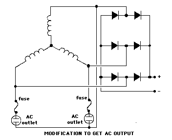
MODIFICATION FOR 110
VOLT AC
Alternators produce rectified DC power. If we tap the
leads attached to the diodes, we can obtain 120 volt AC power. Some, but
not all transformer operated appliances such as TV's, radio's,
fluorescent lights might be possibly be run on this AC.
AC
coming from the alternator is very high frequency and a great many
transformers will overheat at the high frequency. The only way to tell
is to plug the device in for a few seconds, unplug it, and then feel the
transformer or ballast to see if it is overheating. Even this is risky.
Unless you're willing to take the chances involved, you might be better
off converting an induction motor to provide pure 60 cycle AC, described
later on. If you'd still like to give it a try, conversion is a simple
matter of removing diodes, and connecting leads. In most alternators two
wires are soldered to each of the diodes. Remove both from the diode and
attach it to one of three leads. When wired as shown, two outlets with a
common ground can be powered.
Forget about running motor-driven
appliances-unless they use universal AC-DC brush type motors. Ordinary
induction motors are designed for 60 cycles AC. At different frequencies
they will run at different rpm if at all, and will quite possibly
overheat or be destroyed.
REWINDING FOR WINDMILL
USE
Alternators usually loaf along at low rpm, and do not usually
begin to produce a lot of power until they exceed about 1,000 rpm. This
rpm limit can be lowered by rewinding the alternator's stationary coils.
An alternator modified in this way used on a windmill, for instance, can
begin to produce power at a lower wind speed, producing greater total
power output over a period of time.
For example, a 45 amp
Chrysler alternator can be modified by removing each of the 16 turn
coils, and by replacing them with a smaller diameter wire so that each
coil is made up of more turns. AWG #20 plastic coated wire (such as
Belden polythermaleze) obtained from a motor shop can be used to wind
coils of 25 to 26 turns before all available slot space is used. These
coils are then set by dipping in motor varnish and baking with low heat
until hardened. Small diameter wire reduces maximum current available.
Here, No. 20 will handle only about 25 amps with good cooling, but the
extra windings allow the alternator to begin charging at a much lower
rpm. One good reference on motor and generator rewinding is Armature
Winding and Motor Repair by Daniel Breymer available from Lindsay
Publications.
BUILDING A 60 CYCLE
ALTERNATOR
Theory says that any generator can be used as a motor
and vice-versa. If this is so, could we take a common 1/3 hp induction
washing machine motor and use it to produce 120 volts 60 cycle power?
The answer is yes! But we have two problems to solve. First, we must
drive the motor faster than its nameplate rpm to get a 60 cycles per
second output. Second, when we start the unit, we may have to hit the
coils with a DC pulse to start it generating.
Induction motors
have no physical connection between the stationary winding and the
squirrel cage rotor. The electricity flowing in the rotor is created by
transformer action because the magnetic field in the stator winding is
revolving at 1,800 rpm while the rotor is revolving at 1,725 rpm. The 75
rpm difference (4 to 5%) causes a current to be induced in the rotor.
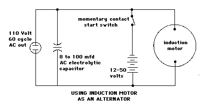
When used as an
alternator, the motor must be driven 4-5% faster than the 1,800 rpm
synchronous speed. This comes to about 1,880 rpm, faster or slower
depending on alternator loading. When the driving speed is exactly
right, the alternator will be producing exactly 60 cycles per second
output power.
Some motors will begin generating power as soon as
they're driven because there's a small amount of residual magnetism
remaining in the rotor and windings. If generation doesn't begin by
itself, you'll probably have to hit the windings with a pulse of DC
current to get it started. A switch connected to a 12 volt battery will
probably be adequate, although in some cases you may need as much as 60
volts to do the job.
A split-phase capacitor-run motor can be
used just as it is, but other motors will probably need a capacitor in
the 8 to 100 microfarad range. Trial and error will determine the exact
size. Make sure the capacitors are rated at 250 to 300 volts AC.
Not all motors will work properly, and we don't really know why.
Fortunately, most motors do. You won't be able to get as much power out
of the motor as the nameplate indicates. To find exactly how much power
you can get, connect ordinary light bulbs to your new alternator one
after another. At some point the alternator will suddenly stop working,
indicating that it is overloaded. This response can sometimes be a
hassle, but it makes the alternator "burn-out proof".
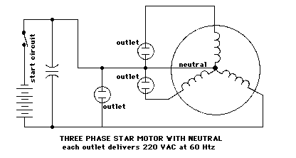
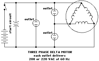
To get large
amount of AC out, you will need a large motor --- over a horsepower. You
may be able to find a large single phase motor on a table saw or on farm
machinery. But you may have to use a three-phase motor. With a
three-phase machine you'll need a capacitor across one of the legs, but
not on all three. Remember though, three-phase motors will generate
power from 208 volts on up. To get 110 volts you'll have to use a large
transformer to step the 208 volts down to 110 volts, and that's not very
practical.
The frequency of the AC out will vary as the engine
rpm varies. How are you going to know when you have 60 cycles per
second? One easy way is to use a motor driven clock. Plug it into the
circuit and leave it there. It only draws a few watts. Compare the
second hand with the seconds counter on a quartz wrist watch. If the
motor clock is running slow, the AC is less than 60 cycle. Adjust engine
rpm until the clock is keeping accurate time.
In conclusion, you
can generate small amounts of 120 volt 60 cycles per second power which
will drive anything from your US TV to your refrigerator using an
induction motor as an alternator. It will take experimentation. When it
works (which is most of the time), it works very well. It's certainly
worth trying.
*******************
Patrick Kelly
engpjk@yahoo.co.uk
http://www.free-energy-info.co.uk/
|