| Heaters The devices described here are probably not “free-energy” devices as such, but in spite of that, it is an area of considerable interest to many people, and the subject is included here because of that. If you do not live in an urban area, then a solid fuel stove can be an economic solution, especially if the fuel can be collected free from wooded areas. Stove design has advanced considerably and it is now possible to make a simple stove with very high efficiency and very low emissions as shown here:  Although this stove is a very simple construction, it’s efficiency is very high indeed. The best fuel is made of smaller pieces which rest on a simple shelf. Branches work better than large pieces of wood as the consumption is more complete. As the fuel is consumed, it is pushed further into the stove, which gives the user an appreciation of the rate of consumption. Having the fuel resting on a shelf has the major advantage of allowing air to flow both above it and below it, which gives improved combustion. The operation is said to be so good that there is virtually no residue and no emissions. Again, if land space is available, a solar oven (or Stirling motor) can be used, either to store energy for later use or generate heat for cooking or home heating, as can hot-water solar panels. However, it is only realistic to consider the application to be during the night in a built-up area with little or no spare space for equipment. Electrical heating, while very convenient, is usually expensive, and it often seems that the effectiveness of an electric heater is not directly related to its power consumption. In theory it definitely is, but in practice it just does not seem that way. There are other alternatives. One of the other documents in this set, shows how to construct a Stanley Meyer style electrolyser which uses ordinary tap water and splits it into burnable fuel using just a low power electrical input: 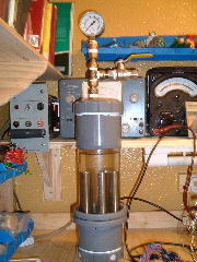 The difficulty in creating a heating system which uses the gas produced by this unit, is in the very high temperature produced when the gas is burnt. Stan overcame this problem with by designing a special burner which mixes air and burnt gasses in with the gas before it is burnt. That lowers the flame temperature to a level which is suitable for heating and cooking:  While this looks a bit complicated, it’s construction is really quite simple. The combination of the Meyer electrolyser and Meyer burner form a system which has the potential of being operated from a solar panel and battery as shown here:  A system like this needs extreme care as the hydrogen / oxygen (“hydroxy”) gas produced is explosive. So:
 The idea is to bubble the hydroxy gas produced by electrolysis of water, through a liquid hydrocarbon such as turpentine. The bubbler should have a large number of small holes in the incoming tube, so that a very large number of small bubbles of hydroxy gas pass through the hydrocarbon. This brings the majority of the hydroxy gas into intimate contact with the hydrocarbon and the process is claimed to convert the hydroxy gas into a new variety of gas which is not explosive, can be stored for later use, and which burns with the same characteristics as coal-gas (“town gas”). At this point in time, I do not know of any recent tests to confirm this, so the claim should be treated with caution and careful tests carried out in the open, lighting the gas remotely and taking refuge behind a robust protective object. Having said that, in my opinion, it is likely that Henry Paine’s claim is correct, but that is only my opinion and I have not confirmed it with any form of practical test. Sang Nam Kim. Mr Kim of Korea also proposes methods of using hydroxy gas for heating and using Henry Paine's hydrocarbon bubbling method. He has four patents on the subject of heating: US 6,397,834 in June 2002 - Heating Furnace US 6,443,725 in September 2002 - Energy Generatin US 6,761,558 in July 2004 - Heating Apparatus US 7,014,740 in March 2006 - Electrolyser The first of these shows his method of getting both beneficial radiant heat and convention heating from a stone construction like this:  This unit is intended as a seriously powerful heating source for a minimum of one room. Mr Kim quotes a hydroxy gas requirement of 30 litres per minute which is a very considerable amount, and if the gas is produced by electrolysis of water at Faraday efficiency, it would need a current draw of 4.2 kilowatts. There is every indication that Mr Kim's method of electrolysis is low efficiency as his latest patent shows a radiator and fan:  Mr Kim also shows a burner intended for use with an existing furnace. He remarks that the outer casing gets to be red hot, running at 1,000oC or more, and so any replication of his design should be treated with care when mounting fixtures are being constructed. In this design, Mr Kim uses the Paine technique and recommends bubbling his hydroxy gas through hexane liquid (C6H14) where 0.3 litres of hexane per hour gets burnt as well as the hydroxy gas. He rates the hydroxy gas requirement of this burner as being 20 lpm, which at Faraday efficiencies, represents 2.8 kilowatts of electricity, although as mentioned before, it is likely that the actual amount of hydroxy gas in his 20 lpm volume is much lower than he thinks, and so will have a lower electrical requirement when using a more electrically efficient electrolyser. His burner is like this:  Mr Kim believes that the hexane prevents flashback ignition. He does not appear to specify the heating material inside the burner but it is probably stainless steel wool. He speaks of gas pressures of 1 Kg per sq. cm., which, if my calculations are correct is 14.22 psi. which is not possible for 100% hydroxy gas as it will explode spontaneously at 12 psi. due to its high energy state and electrical charge. He states that the secondary flames at the top of the unit "burn with a blue flame colour" and that is different to the flame colour lower down. Mr Kim believes that the hydroxy burnt at the bottom of the burner forms water vapour which is then split into hydroxy gas again by the very high temperature and that is the reason for the blue flames at the top. Personally, I don't believe that this will take place and that the effect may have a good deal to do with the hexane liquid being burnt. However, this burner design appears to be a good one for lower grades of hydroxy gas. If a higher grade of hydroxy gas is being used, please be aware that a hypodermic-size tiny burner orifice will be needed to avoid flashbacks and no commercial flashback arrester will work reliably with good quality hydroxy gas on every occasion and so a bubbler is absolutely essential. Electric power is very popular for heaters. However, with most appliances, it is a very expensive form of heating. There is a technique which is reputed to improve the efficiency and lower the cost of electric heating. This method involves rotating a cylinder inside an outer cylinder and filling part of the narrow space between the cylinders with some variety of light oil. This method has been patented more than once. In 1979, Eugene Frenette was granted patent 4,143,639 where a single motor is used to rotate the drum and power a fan to boost the motion of the hot air:  It is not immediately obvious why this arrangement should work well, but it appears that it does. As the inner drum spins around, the oil rises up between the two inner cylinders. It lubricates the bearing under the rotating drum and the rotation causes the oil to heat up. This heats the middle cylinder and air being drawn up around it by the action of the fan blade, is also heated before being pushed out of the top of the heater. After a few minutes, the outer housing becomes so hot that the thermostat attached to it, cuts off the electrical supply. The heater does not stop heating at this time as air continues to circulate through the heater by ordinary convection. In my opinion, it would be more effective if the fan motor were operated independently and did not cut off when the heater reaches its operating temperature. Very similar systems were patented by Eugene Perkins: January 1984 patent 4,424,797, November 1984 patent 4,483,277, March 1987 patent 4,651,681, October 1988 patent 4,779,575, and in January 1989 patent 4,798,176. His first patent shows a horizontal drum which is completely immersed in the liquid:  This calls for a much greater accuracy of construction in that the liquid has to be contained even though it has a rotating shaft running through the housing. This device pumps the heated liquid through central-heating piping and radiators. In his later patent of the same year, he shows a modified version with two drums and an impeller:  The “heat exchanger” is a radiator or set of radiators. He progressed to a system where the shaft rotation forces the liquid to be expelled through the tips of arms radiating out from the centre of the impeller hub:  Here, the liquid is forced into a small space between the rotor and its drum housing. This system has been used very successfully for water heating and some measurements indicate that it is at least 100% efficient and some people believe that it is well over the 100% efficiency, though they don’t want get drawn into long discussions on methods of measurement. It is sufficient to say here, that this method is very effective indeed. Frenette Variation: The Frenette heater design shown above with it’s two vertical cylinders, is not the easiest for the home constructor unless one of the cylinders (presumably the inner one) is constructed from steel sheet, as it is difficult to find two commercially available steel cylinders of just the right relative size to produce the wanted gap between them. A much easier variation replaces the inner cylinder with a stack of circular steel discs. As these can be cut from 20 gauge steel sheet fairly readily by the home constructor, or alternatively, cut by any local metalworking or fabrication company, any available size of outer cylinder can be used and the disc diameter chosen accordingly. The discs are mounted about 6 mm (1/4”) apart on a central steel rod which is rotated in order to drive the discs through the oil contained inside the body of the heater. While this looks like a Tesla Turbine, it is not because the spacing of the discs creates a different effect. The wider disc spacing creates shear as they spin through the surrounding oil, and this shearing creates a high degree of heating. It must be remembered that this is a heater, and the outer canister gets very hot during operation (which is the whole point of the exercise in the first place). For that reason, oil is used as a filling and not water, which boils at a much lower temperature. The larger the diameter of the canister and the greater the number of discs inside it, the greater the heat developed. To ensure that the discs do not come loose during prolonged operation, a hole can be drilled through them just outside the area covered by the locking/spacing nuts, and a stiff wire run through the holes and the ends either welded to the central rod or pushed through a hole drilled in it and bent over to hold it in place. The heat of the cylinder can be circulated by attaching a simple fan blade to the spinning shaft. This blows air down the hot sides of the canister, moving it towards the floor which is the most effective place for it circulate and heat the entire room. As the discs spin, the oil is pushed outwards and moves upwards, filling the top of the canister and building up some pressure there. This pressure can be relieved by running an external pipe from the top of the cylinder back to the bottom, allowing the oil to circulate freely. This has the decided advantage the circulating oil can be passed through a radiator as shown in the following diagram:  The central rod can be rotated by any convenient motor, conventional, Adams type, pulse-motor, permanent magnet motor, or whatever. An alternative to this style of operation, is to use the rotating motor to spin a ring of permanent magnets positioned close beside a thick aluminium plate. The eddy currents cause very strong heating of the aluminium plate which then can have air blown across it to provide space heating. The Peter Davey Heater. During World War II, Peter Daysh Davey, of Christchurch, New Zealand, a fighter pilot and musician, designed and built an unusual water heater. This design is not particularly well known and information is fairly thin on the ground, however, the basic principle and design details are known.  The device is intended to operate on the New Zealand mains power supply of 220 volts 50 Hz and a requirement of the apparatus is that it resonates at that 50Hz frequency. Resonance is a frequent requirement of free-energy systems, and the need for it is often overlooked by people who attempt to replicate free-energy devices. Properly built and tuned, this heater is said to have a COP of 20, which means that twenty times as much heat is produced by the device, compared to the amount of electrical power required to make it operate. This power gain is caused by additional energy being drawn from the immediate environment and it is very important as the largest use of energy in cool climates tends to be that used for heating. If that can be reduced by a serious amount, then your annual power costs should be much lower as a result of it. Peter was granted a New Zealand patent for his heater on 12th December 1944 but he found that after the war, the opposition from the utility companies was so great that it prevented him from going into commercial production with it. For fifty years, Peter kept up his attempts to get sufficient approval to bring his heater to the marketplace, but the opposition finally won and he never managed it. The device comprises a hemispherical resonant cavity, formed from two metallic dome shapes, both of which resonate at 50Hz. Initially, Peter used two bicycle bells and he found that when submerged in water, the device brought the water to the boil in a very short time indeed. The construction is like this:  If construction were to use two identical hemispheres, then the cavity between them would be anything but even width throughout, but the resonance would be the same. On the other hand, if you want the resonant cavity between the two hemispheres to be of constant width, then the outer sphere needs to be markedly larger than the inner hemisphere. The outside of both hemispheres needs to be insulated unless mounted in such a way that it is not possible to touch the hemispheres, as each is attached to the mains. In the above diagram, the mains live wire 6, is fed through the connecting pipe 8, and clamped to the inside of the inner hemisphere 1, by nut 3 which screws on to the threaded section of tube 8. It is important that it is the live wire which is connected to hemisphere 1. The mains neutral wire 7, is also fed through the connecting tube 8, exits via a small hole and is clamped on to the outside of the outer hemisphere 2, by nut 5, also on the threaded section of tube 8. The two hemispheres are held apart by a spacing washer 4, which is made from a high-temperature non-conducting plastic. As the tube 8 connects electrically and mechanically to both mains wires via the two locking nuts 3 and 5, it is essential that this tube is constructed from an electrically non-conducting material such as plastic. As the tube will be in boiling water on a regular basis, it is also necessary that the tube material is also able to handle temperatures over 100o C (212o F), so possible materials include nylon and teflon. This washer is a key component of the heater and its thickness is key to the efficiency of the whole device. This thickness L, is the tuning control for the cavity. The outer hemisphere is about 8 mm greater in diameter than the diameter of the inner hemisphere. Allowing for the thickness of the metal of the bowl, the resonant cavity will therefore be about 3 mm or one eighth of an inch. The hemisphere 1 is also tuned to 50 Hz by grinding it carefully until it resonates freely at that frequency. Connecting a loudspeaker in series with a resistor of say, 100K ohms, will give a sound of the exact frequency with which this hemisphere needs to resonate. This tuning needs to be done with the unit fully assembled as the connections to the tube will alter the resonant frequency of the hemisphere. When this is being done, the resonance will be felt rather than heard, so hold the tube lightly so that it can resonate freely. The tuning is done by removing a small amount of metal from the face of hemisphere 1 and then testing for resonance again. When hemisphere 1 resonates well at the mains frequency, (roughly G two octaves below middle C on a keyboard), the search for high-efficiency heating is carried out by very small adjustments of the gap L. The adjustment of the gap L is carried out by very careful grinding down of the separating washer 4 and the result is best determined by measuring the length of time needed to boil a known volume of water and the current taken to do that. Repeated tests and recorded results, shows when the best gap has been reached and the highest efficiency achieved. The heater can, of course, be used to heat any liquid, not just water. This heater is unlike a standard kettle heating element. In the standard method, the water is not a part of the main current-carrying circuit. Instead, the mains power is applied to the heater element and the current flowing through the heater element causes it to heat up, and the heat is then conveyed to the water by conduction. In Davey’s heater, on the other hand, the current flow appears to be through the water between the two hemispheres. It seems likely that the actual heating is not produced by current flow at all, but from cavitation of the water caused by the resonating of the cavity between the two hemispheres. This technique is used in small jewelry cleaners where and audio frequency is applied to a cleaning fluid in a small container. A small amount of electrolysis will take place with the Davey heater as it in effect also forms a single parallel-connected electrolyser. The amounts should be very small as only 1.24 volts out of the 220 volts applied will be used in the electrolysis process. An early construction of the original heater is shown in the photograph below. The coin shown in the picture is 32 mm (1.25 inch) in diameter. The heater is submerged in water when it is being used, and it brings that water to the boil exceptionally quickly. The unit was tested by New Zealand scientists who were able to vouch for its performance, but who were unable to state exactly how its operation allowed it to output such a high level of heat for such a low level of electrical input. You will notice from the photograph, how carefully the electrical connections and outer bowl are insulated. 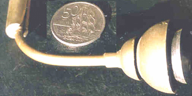 The original prototype which Peter made was constructed from the tops of two bicycle bells, only one of which was tuned to 50 Hz. This shows that the device will definitely work if the inner hemisphere is tuned correctly. You can find forum investigation here and more recent information here. Here is an interesting article from the Home Power web site. If you are interested in renewable power, then I strongly recommend that you visit their web site and consider subscribing to their magazine as they cover many practical topics using simple wording.  The initial goal of our project was to build a functional, permanent magnet alternator from scratch, primarily out of wood. When the alternator was together and working, it became clear that wind was the logical energy source for it. This unit (we call it the “Wood 103”) is not intended to be a permanent addition to a remote home energy system, but a demonstration of how simple it really is to produce energy from scratch—and to be a bit silly! Many home-made wind generator designs require a fully equipped machine shop to build. Our wooden version, built in a day, can be made with mostly local materials and simple hand tools in any remote corner of the world. The alternator design is well suited to hydroelectric, human, or animal power. We plan to use it for a series of magnet and electricity demonstrations at local schools, and for future experiments with different energy sources, windings, cores, poles, and rotors. This project will cost you only US $50–75, depending on what you pay for magnets and wire. Alternator Basics Electricity is simply the flow of electrons through a circuit. When a magnet moves past a wire (or a wire past a magnet), electrons within the wire want to move. When the wire is wound into a coil, the magnet passes by more loops of wire. It pushes the electrons harder, and can therefore make more electricity for us to harvest. The magnetic field can be supplied by either permanent magnets or electromagnets. All of our designs use permanent magnets. In a permanent magnet alternator (PMA), the magnets are mounted on the armature (also sometimes called the “rotor”), which is the part that spins. It is connected directly to the wind generator rotor (the blades and hub). There are no electrical connections to the armature; it simply moves the magnets. Each magnet has two poles, north (N) and south (S). The magnets are oriented in the armature so that the poles alternate N-S-N-S. The other half of a PMA is the stator, which does not move. It consists of an array of wire coils connected together. The coils in our stator alternate in the direction they are wound, clockwise (CW) and counter-clockwise (CCW). The coils and magnets are spaced evenly with each other. So when the north pole of a magnet is passing a clockwise coil, the south pole of the next magnet is passing the counter-clockwise coil next door, and so on. The coil cores are located inside or behind the coils, and help concentrate the magnetic field into the coils, increasing output. The cores must be of magnetic material, but also must be electrically non-conductive to avoid power-wasting eddy currents. The air gap is the distance between the spinning magnets and the stationary coils (between the armature and the stator), and must be kept as small as possible. But the spinning magnets must not be allowed to touch the coils, or physical damage to them will occur.  The more loops of wire that each magnet passes, the higher the voltage produced. Voltage is important, since until the alternator voltage exceeds the battery bank voltage, no electrons can flow. The sooner the alternator voltage reaches battery voltage or above in low winds, the sooner the batteries will start to charge. Increasing the number of turns of wire in each coil allows higher voltage at any given speed. But thinner wire can carry fewer electrons. Using thicker wire allows more electrons to flow, but physical size limits the number of turns per coil. This also explains why enamelled magnet wire is always used in coils. The enamel insulation is very thin, and allows for more turns per coil than does thick plastic insulation. Any alternator design is a compromise between the number of turns per coil, the wire size, and the shaft rpm. The electricity produced by an alternator is called “wild” alternating current (AC). Instead of changing direction at a steady 60 times per second like standard AC house current, its frequency varies with the speed of the alternator. Since we want to charge batteries, the wild AC is fed to them through a bridge rectifier, which converts AC to DC (direct current) for battery charging. The alternator may produce much higher voltages than the battery bank does, but the batteries will hold the system voltage from the wind generator down to their normal level when charging. 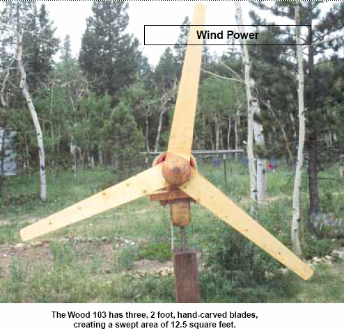  Design We had successfully converted AC induction motors into PMA wind generators before. But starting from scratch was truly a first-time experiment. Our design choices for wire size, number of windings, number of poles, blade pitch, and other factors were intuitive rather than calculated. Every wind generator, waterwheel, and alternator we’ve built has produced usable energy, no matter how strange the design. The trick is matching the generator, rotor, and energy source. You can do a lot of study and calculation to get there. But if the design is quick, cheap, and easy to build, why not just make adjustments by observing the unit’s performance? If you try this project and change the wire size, magnet type, rotor design, and stator cores, you’d still be making usable energy and have a great starting point for further research. Just change one thing at a time until the unit performs to your satisfaction. We’re aware that many design improvements could be made to the Wood 103—and we hope that others will experiment with variations. Wooden Alternator The biggest problem with building most wind generator designs at home is the need for machine tools -usually at least a metal lathe is required. Headquarters for our business, Otherpower.com, is high on a mountain, 11 miles (18 km) past the nearest utility line. We are lucky enough to have basic tools up here, but many folks around the world don’t. That’s the main reason we used so much wood in this design.  It is possible to build human-powered woodworking tools in almost any location. With some patience, only simple hand tools are required for this project. If you want to build it in a day, though, a lathe, drill press, band saw, and power planer can be very helpful! Building the Armature The key to the Wood 103’s armature is the neodymium-iron-boron (NdFeB) magnets. They are the strongest permanent magnets available. Ours are surplus from computer hard drives. They are curved, and measure about 13/4 by 13/8 by 1/4 inch thick (44 x 35 x 6 mm). Eight fit together in a 37/8 inch (9.8 cm) diameter ring. That’s why we chose this particular diameter for the armature.  The magnets are available with either the north or south pole on the convex face. For this project, you will need four of each configuration. Don’t start tearing your computer apart to get these, though! They are from very large hard drives, and you won’t find any inside your computer. Check the Access section at the end of this article for suppliers. To construct the armature, we laminated plywood circles together with glue. The 37/8 inch (9.8 cm) diameter wooden cylinder is 33/4 inches (9.5 cm) long, with a 13/4 inch (4.4 cm) wide slot cut into it 1/4 inch (6 mm) deep to tightly accept the magnets. To assure that the magnets would be flush with the armature surface, we cut the plywood disks a bit oversized, and turned them down on the lathe to the proper diameter. The same procedure was used to cut the magnet slot to exactly the right depth. Using a firm grip, we carefully press-fit and epoxied the magnets into place. Remember that these magnets come in two different configurations—north pole on the convex face and south pole on the convex face. The magnets must have alternating poles facing out, and this is how they naturally want to align themselves. Next, we drilled the shaft hole through the centre of the armature using a lathe, though it could certainly be done with a hand drill if you are careful to align it perfectly. We roughed up the surface of the shaft with a file before epoxying it into the hole. It should be a very tight fit—we had to gently tap it through with a hammer. This may not be strong enough, and it might be wise to actually pin the armature to the shaft. Time will tell! Construction without a Lathe We did cheat by using a lathe to shape the armature, but a coping saw and sandpaper would work just fine. If a lathe is not available, our suggestion is to first cut out the disks, making sure that some of them (enough to stack up to 13/4 inches; 4.4 cm) are 1/4 inch (6 mm) smaller in diameter than the rest. Once assembled, the armature will then have a recessed slot for the magnets. Otherwise some means of “lathing” the slot will have to be devised. It could be done on the alternator’s pillow blocks with a sanding block mounted below, or in a drill press. It would also be wise to first drill a shaft hole into each plywood disk, and then assemble, glue, and clamp all the plywood disks together on the shaft before turning. Building the Pillow Blocks The pillow block bearings were made from pine, since that’s the hardest wood we have available up here on the mountain. Certainly hardwood would be much better. First we drilled a hole slightly under 3/8 inch (9.5 mm) diameter in each pillow block. Using a gas stove burner, we heated the shaft to almost red hot, and forced it through the holes. This gave a good tight fit, hardened the wood, and made a layer of carbon on the inside for better lubrication. We drilled a small hole in the top of each pillow block, down into the shaft hole, so the bearings can be greased  After pressing the hot shaft through the pillow blocks, we were very pleased with how freely the armature turned and how little play there was. In a slow waterwheel design, wood/carbon bearings would probably last for years. This wind generator is a actually a fairly high-speed unit, and real ball bearings would be a big improvement. Such bearings could be easily scavenged from an old electric motor of any kind. Wooden bearings were certainly simple, fast, and fun though!  Building the Stator The stator, on which the coils are wound, is made up of two identical halves. Each half is made from 2 by 4 inch lumber, 6 inches long (5 x 10 x 15 cm). A semi-circular cut-out with a 5 inch diameter (12.7 cm) was made on each half. The tolerances are pretty tight, but this allows more than a 1/2 inch (13 mm) to fit the coils and core material inside. On the sides of the 2 by 4s, right over the cut-out, we of this type is often available from electronics stores or glued thin (1/8 inch; 3 mm) U-shaped plywood “half disks,” which have an inner diameter of 4 inches (10 cm) and an outer diameter of 6 inches (15 cm). They have slots cut large enough to accept the coils. These were made with a hand saw, 3/8 inch (9.5 mm) drill bit, and a rat tail file. The coils are wound in these slots, and the space inside and behind the coils is filled with the magnetite core material. There are four coils on each half of the stator, and they must be evenly spaced. Our twin stator halves are wound with #22 (0.64 mm diameter) enamelled copper magnet wire. Magnet wire of this type is often available from electronics stores or from electric motor repair shops. Each stator half contains four coils. Each coil is 100 turns, and every coil is wound in the opposite direction as its neighbour. It’s important to wind the coils neatly and tightly, using a wooden dowel to carefully press each winding loop into place. 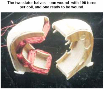 Most common alternators use thin steel laminates as cores, to help concentrate the magnetic field through the coils. Magnetism in motion pushes the electrons around in the steel too. The laminates are insulated from each other to block these eddy currents, which would otherwise waste energy. These laminates are difficult to make in a home shop, so we chose dirt as our stator core—actually magnetite sand mixed with epoxy. It is not as effective as real laminates, but was very easy to use, and available for free by separating it from the dirt in our road. We mixed the magnetite with epoxy and simply spooned it into the open cores. If the cores were left empty (an “air core”) the alternator would still work, but with much less power. Magnetite is a common mineral, a type of iron oxide. It is a by-product of some gold mining operations, and can sometimes be purchased. As an alternative, we simply dragged a large neodymium magnet (just like the ones we used for the armature) around on our local dirt road on a string for a while, attracting all the ferrous sand, which stuck to the magnet. 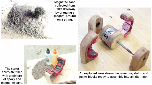 We separated this somewhat magnetic sand into a pile, sifted it through a window screen, and sorted that with the magnet one more time. The remaining black sand sticking to the magnet was nearly pure magnetite. A quick test of any local dirt pile with a neodymium magnet should reveal whether your sand contains magnetite. If not, try dragging the magnet along the sandy bottom of a local river. Any deposits of black sand on the river bottom are most likely nearly pure magnetite. The clearance between the stator coils and the armature surface is very important. It must be extremely close (within 1/16 inch; 1.5 mm) without allowing the magnets in the armature to touch the stator. Our model is actually a bit sloppy—the clearances are more like an 1/8 inch (3 mm). Tighter tolerances would produce more power. Wiring Configuration The completed stator consists of two identical sets of four coils. For our wind generator, we connected the stator halves in parallel for more current (amperage). Connecting them in series would double the voltage produced, but halve the amperage. For low wind speeds, a series connection would be the best—the alternator would reach charging voltage at slower speeds. At higher speeds, a parallel connection is optimum for producing the most amperage. An ideal system would contain a regulator that switched the stator connections from series to parallel when the unit began to spin fast enough. As is the case with many home-brew and commercial wind turbines, we eliminated this entirely, sacrificing a small amount of efficiency for much greater simplicity and reliability. Many people have experimented with such regulators, both solid state and mechanical. Alternator Performance We were really surprised by this alternator’s performance. We could easily spin it with our fingers and get 12 volts or higher. A cordless drill attached to the shaft would light up a 25 watt, 12 V DU light bulb easily. This might not seem breath-taking, but considering the simplicity of the project and one-day construction time, we were quite impressed. Our 100 watt rating for the Wood 103 is probably right on, considering the performance we got during testing, and the way commercial wind generator manufacturers rate their products. Our data acquisition system was pretty simple - multimeters and people with pencils and paper to watch them and record measurements. With a series connection between the stator halves, the unit reached charging voltage for 12 volt batteries at around 300 rpm. With the stator in parallel, it took around 600 rpm to start charging. When installed in our wind machine, the parallel connection gave us 4.8 amps output in a 25 mph (11 m/s) wind. Building the Frame To stay with the style of this project, we chose to build the rest of the wind generator out of wood too. It’s a very simple design and should be self-explanatory. It’s all glued and pinned with dowels. No bolts are used except to connect the alternator to the frame. We admit that we cheated here! We did not make any provision for over-speed control, since this was intended to be a demonstration unit for all energy sources, not just wind. A canted tail and spring assembly could be added to control speed during high winds. And, of course, making the frame out of surplus steel or aluminium angle would give great improvements in durability. We also did not include slip rings for power transmission as the wind generator yaws. Instead, we used flexible wire for the first few feet, letting it hang in a loose loop. A piece of aircraft cable cut slightly shorter than the power cable was attached, so if the power wire gets wrapped around the pole too tightly, the connections won’t pull loose. Our normal winds are usually from one direction, and designs without slip rings seem to work fine up here. Wrapping the power wire around the pole is only rarely a problem, and this strain relief cable prevents any damage. Our experience is that if the power cable does wind up all the way, it will eventually unwind itself. 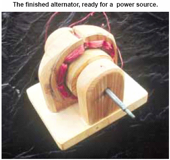 Designing the Rotor The “rotor” here refers to the blades and hub of the wind generator. We don’t profess to be experts in blade design. Once again, we chose our starting point intuitively rather than trying to calculate the proper blades to match our alternator’s power curve. Since the blade carving process took us less than an hour for the whole set of three, we figured that any design changes would be quick and easy to make. However, because we glued the blades to the hub, a new hub will be necessary for any blade changes. There’s a great deal of information out there about building blades. Hugh Piggott’s Web site and his Brake-drum Wind Generator plans are some of the best sources around. The rotor was built from 3/4 inch by 4 inch (19 mm x 100 mm) pine lumber. Each blade is 3 1/2 inches (90 mm) wide at the base and 2 1/2 inches (64 mm) wide at the tip. The three blades are 2 feet long (600 mm), for a total diameter of 4 feet (1.2 m). The pitch of the blades is 10 degrees at the hub, and 6 degrees at the tip. The hub is made from 2 inch (50 mm) thick wood, press-fit and glued to the roughed-up shaft with epoxy. The blades are held on to the hub by one small nut at the end of the shaft, and several wooden pins with glue. Carving the Blades To prepare the blades for carving, we simply drew a few lines so that we knew what material to remove. Each blade starts out life as a 2 foot (0.6 m) long, 1 x 4 inch (25 mm x 100 mm). Starting from the leading edge of the blade at the hub, we simply used a protractor to lay out how far into the wood, 10 degrees of pitch would take us at the trailing edge - about 5/8 inch (16 mm). At the tip, the pitch is about 6 degrees, so we removed about 3/8 inch (9.5 mm) of material from the trailing edge. We made both marks, and connected the two with a line. We then simply took a power planer, and followed the cut depth line all the way up the blade. 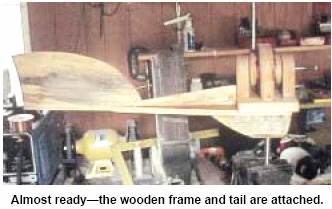  For better accuracy (or if you don’t have a power planer), you can use a hand saw to make cuts across the blade every inch or so, down to the cut depth line on the trailing edge and not cutting at all on the leading edge. Using a hammer and chisel, it’s easy to break out the chunks of wood to the proper depth. Then smooth the blade down to the proper angle with a hand plane. When the saw kerfs disappear, the blade pitch is correct. The blade width taper occurs on the trailing edge. We simply used a saw to cut the first taper, and used that first blade as a template for cutting the others. No calculations were made for the airfoil shape on the other side of the blades. We picked a likely looking profile and started cutting with the power planer. A hand planer is fine for this process, too. After everything looked good and even, we sanded the blades and treated them with linseed oil. Balancing the Blades To avoid vibration problems and enable easy starting, we made some effort to balance the blades. We considered them reasonably balanced when each blade weighed the same (about 8 ounces; 227 g) and had the same centre of gravity. Adjustments can be made quickly with a planer. Once this is done, and all three blades are assembled on the hub, balance can be double-checked by spinning the rotor and making sure it has no tendency to stop in any one place. This is a quick process, and we certainly were not concerned about great precision here. As it turned out, a small effort in balancing the blades yielded good results, and the machine seems well balanced and vibration free. Truly, one could write an entire book on blade design, and it can get complicated. Don’t worry, though. It is possible to make a very basic blade that will work quite effectively. Often a simple blade with a constant 5 degree pitch from hub to tip and a reasonable airfoil on the backside will work very nicely. If you are interested, explore the books and Web sites listed at the end of this article for more information on blade design. Testing For testing, we strapped the Wood 103 to our trusty Model A Ford. The Model A serves as a reliable daily driver, and with the bracket we made, it makes an excellent testing facility for wind turbines. It has a perfectly accurate speedometer, which has been carefully checked by the Fort Collins, Colorado Police Department’s radar machines! We carry a 12 volt battery, a voltmeter, an ammeter, and pencil and paper in the test vehicle. On a still day, we can observe the speedometer and take accurate windspeed versus output measurements on any wind turbine. We’ve used this rig with props over 8 feet (2.4 m) in diameter. The cost of a good Model A (about US $4,000 if you don’t mind a jalopy) is not included in the price of this project! Wind generators should be installed high above human activity. For testing purposes, we've run our generator on low towers within reach of people, and on our Model A. Wind generators have parts that spin very fast! The blades could probably take your head off in a high wind if you were silly enough to walk into them. Make all installations well out of reach of curious organisms. You should treat any wind generator with a great deal of respect. This is not a joking matter, though we always shout “Clear prop!” before we fire up the test vehicle... 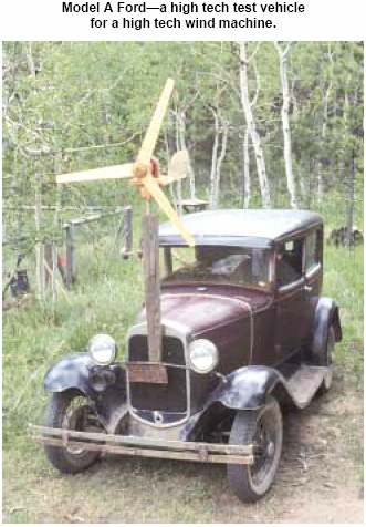 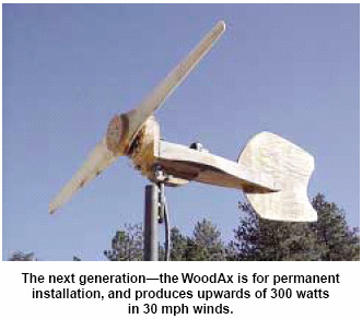 Improvements Many improvements could be made to this design. But the intention was to use mostly wood and hand tools, and keep it fast and simple. The wooden alternator is easy and quick to build, but for longest life, it would need to be protected from rain and snow. Maybe a small shingled roof over it? Using real ball bearings would help friction loss and longevity a bunch. A metal frame and tail would improve high-wind survivability significantly. A furling system to keep the Wood 103 from destroying itself during a gale would be a great addition too. We plan to experiment with many improvements, and we hope this project piques the interest of others too. Trade-Offs Designing and building a permanent magnet alternator involves a long series of trade-offs. For example, thicker wire in the windings would give more possible current, but less room for windings and hence lower voltage at the same rpm. Ceramic magnets might be cheaper, but would give far less power than neodymium magnets. Series wiring on the stator would allow lower rpm at charging voltage, but parallel gives better charging current—and a regulator to switch between the two would be complicated. Using steel laminates instead of air or dirt stator cores would produce more power, but laminate production is extremely difficult. The trade-offs involved in designing a complete wind generator (or water turbine, or bicycle generator) are even more lengthy and complicated. Wind speed, rotor diameter, number of blades, blade pitch, width and twist, optimum rpm for your winding configuration, generator diameter, and number of poles all factor into a perfect final design. Improvise, But Do it! We’ve tried to demonstrate how easy it is to produce electricity from scratch. Don’t let yourself get hung up on complicated formulas, calculations, and machine tools. Even if you make many changes to this simple design, you’ll still almost certainly have a unit that makes usable energy for charging batteries. Then, you can make small improvements until it performs exactly right for your application. And it could be powered by wind, falling water, a human on a bicycle, a dog on a treadmill, or a yak in a yoke! Access Dan Bartmann and Dan Fink, Forcefield, 2606 West Vine Dr., Fort Collins, CO 80521 • 877-944-6247 or 970-484-7257 • danb@otherpower.com danf@otherpower.com • www.otherpower.com Magnets, magnet wire, bridge rectifiers, free information, and a very active discussion board All Electronics, PO Box 567, Van Nuys, CA 91408 888-826-5432 or 818-904-0524 • Fax: 818-781-2653 allcorp@allcorp.com • www.allelectronics.com Magnets, rectifiers, and lots of electronics parts at great prices American Science and Surplus, 3605 Howard St., Skokie, IL 60076 • 847-982-0870 • Fax: 800-934-0722 or 847-982-0881 • info@sciplus.com • www.sciplus.com Magnets, magnet wire, surplus electronics, bearings, and other neat stuff Marlin P. Jones and Assoc., PO Box 530400, Lake Park, FL 33403 • 800-652-6733 or 561-848-8236 Fax: 800-432-9937 or 561-844-8764 • mpja@mpja.com www.mpja.com • Magnet wire, rectifiers, electronics, tools, test equipment Hugh Piggott, Scoraig Wind Electric, Scoraig, Dundonnell, Ross Shire, IV23 2RE, UK • +44 1854 633 286 • Fax: +44 1854 633 233 hugh.piggott@enterprise.net • www.scoraigwind.co.uk Wind generator and alternator designs, lots of free information about blade design and carving WindStuffNow, Edwin Lenz, 10253 S. 34th St., Vicksburg, MI 49097 • 616-626-8029 elenz@windstuffnow.com • www.windstuffnow.com Alternator designs, parts, useful formulas, free information, and blade design software American Wind Energy Association (AWEA) discussion board • http://groups.yahoo.com/group/awea-windhome • Join the list by sending a blank e-mail to: awea-wind-home-subscribe@yahoogroups.com www.awea.org Frank Herbert’s Windmill. As has been carefully explained by the above article, if a windmill of the blade variety is mounted low down then it is dangerous, and people on sailing boats have been killed by them. Also, if the blade arrangement is designed to operate well in low wind conditions, then it is not unusual for there to be a problem if the wind rises to gale force or higher, with some generator designs giving up and switching off entirely, even though the available free energy is at its highest level. This design by Frank Herbert is perfectly capable of being home-built and yet it overcomes these problems as well as being a high-efficiency wind turbine. It has an outside cage which prevents human access to the moving parts inside and the ‘cage’ is not just for protection but is there to enhance the performance of the device. In passing, windmills can be used to compress air and compressed air cylinders can be used to power vehicles and/or power electrical generators during periods of heavy power requirements. The following information is from Frank Herbert’s US Patent 4,142,822 of 1979:  The vertical housing 22 shown dotted here, surrounds the vertical power take-off shaft 26. The wind is allowed to flow through this housing at any angle, so there is no need for the housing to move. In the diagram above small discs 44 are shown at each end of the vertical shaft. These discs have arms 42 extending outwards to support a series of vertical vanes or pressure surfaces 24. For clarity, just one vane is shown through there will actually be many of these (rather like the cutting blades on a cylinder lawnmower). In reality, there will be no arms on the discs 42 as it is much easier just to have a full-width solid disc supporting the vanes. The outer housing has a series of vertical slats which are angled to direct the incoming wind on to the vanes at the best possible angle:  This top view of part of the device, shows the main mounting shaft 26 on which the top and bottom rotor discs are mounted. The red dots show the pivot points where the vanes 24 can turn to take the greatest advantage of the wind pressure. The incoming wind 36, is deflected by the slats of the housing 32, to give it a good angle when flowing through the device as well as keeping humans away from the spinning mechanism. As the vanes and slats are located all the way around shaft 26, sudden changes in wind direction and/or wind strength have no particular effect on this design as it operates with wind coming from any direction and no physical movement of any part of the device is needed for a change in wind direction. The vanes can have various different profiles and still work well. The shape shown above is the shape of an aircraft wing, where a force acting towards the curved surface is generated when air flows around the shape. This is not a particularly difficult shape to construct and it is very effective in an airflow (which is why it is used to lift aircraft off the ground). There can be any convenient number of vanes and a device built as shown above should be very effective.. As the overall efficiency is improved if there is no turbulence inside the device, Frank has found a method of minimising this. For this, he uses a mechanism which can alter the shape of the vanes when the windspeed gets high. The higher windspeed whirls the vanes around faster, causing higher ‘centrifugal’ forces on the vanes which Frank uses as follows. Weight 54 gets pushed across by the spin rate of the rotor.  This pushes against the spring 56, compressing it. The triangle link 59 moves upwards, pivoting at points 59a and 59c, and raising section 50 of the vane. This changes the shape of the vane as shown here:  The result of this changed shape is to reduce turbulence inside the device and raise the overall efficiency. Mead and Holmes. The US patent 4,229,661 dated 1980 from Claude Mead and William Holmes is entitled “Power Plant for Camping Trailer” proposes the use of a wind power generator to store compressed air for later use in providing household electrical current, and simultaneously charge batteries which can be used to drive the compressor in periods of very high electrical demand. There is also an option for a rapid system charge if AC mains power becomes available:  Solar Ovens. This information comes from http://solarcooking.org/plans/funnel.htm and ownership remains with the original authors and this material is reproduced here with their kind permission. How to Make and Use The Brigham Young University Solar Cooker/Cooler by Professor of Physics at Brigham Young University (BYU), with Colter Paulson, Jason Chesley, Jacob Fugal, Derek Hullinger, Jamie Winterton, Jeannette Lawler, and Seth, David, Nathan, and Danelle Jones. 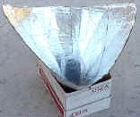 Introduction A few years ago, I woke up to the fact that half of the people in the world must burn wood or dried dung in order to cook their food. It came as quite a shock to me, especially as I learned of the illnesses caused by breathing smoke day in and day out, and the environmental impacts of deforestation - not to mention the time spent by people (mostly women) gathering sticks and dung to cook their food. And yet, many of these billions of people live near the equator, where sunshine is abundant and free. So..... As a University Professor of Physics with a background in energy usage, I set out to develop a means of cooking food and sterilising water using the energy freely available from the sun. First, I looked at existing methods. The parabolic cooker involves a reflective dish which concentrates sunlight to a point where the food is cooked. This approach is very dangerous since the sun's energy is focused to a point which is very hot, but which cannot be seen. (Brigham Young University students and I built one which will set paper on fire in about 3 seconds!). I learned that an altruistic group had offered reflecting parabolas to the people living at the Altiplano in Bolivia. But more than once these parabolas had been stored next to a shed -- and the passing sun set the sheds on fire! The people did not want these dangerous, expensive devices, even though the Altiplano region has been stripped of fuel wood. The box cooker is basically an insulated box with a glass or plastic lid, often with a reflecting lid to direct sunlight into the box. Light enters through the top glass (or plastic), to slowly heat up the box. The problems with this design are that energy enters only through the top, while heat is escaping through all of the other sides, which have a tendency to draw heat away from the food. When the box is opened to put food in or take it out, some of the heat escapes and is lost. Also, effective box cookers tend to be more complicated to build than the funnel cooker. While studying this problem, I thought again and again of the great need for a safe, inexpensive yet effective solar cooker. It finally came to me at Christmastime a few years ago, a sort of hybrid between the parabola and the box cooker. It looks like a large, deep funnel, and incorporates what I believe are the best features of both the parabolic cooker and the box cooker. The first reflector was made at my home out of aluminium foil glued on to cardboard, then this was curved to form a reflective funnel. My children and I figured out a way to make a large cardboard funnel easily. (I'll tell you exactly how to do this later on.) The Solar Funnel cooker is safe and low cost, easy to make, yet very effective in capturing the sun's energy for cooking and pasteurising water -> Eureka! Later, I did extensive tests with students (including reflectivity tests) and found that aluminised Mylar was good too, but relatively expensive and rather hard to come by in large sheets. Besides, cardboard is found throughout the world and is inexpensive, and aluminium foil is also easy to come by. Also, individuals can make their own solar cookers easily, or start a cottage-industry to manufacture them for others. Prototypes of the Solar Funnel Cooker were tested in Bolivia, and outperformed an expensive solar box cooker and a “Solar Coolkit” while costing much less then either. Brigham Young University submitted a patent application, mainly to insure that no company would prevent wide distribution of the Solar Funnel Cooker. Brigham Young University makes no profit from the invention. (I later learned that a few people had had a similar idea, but with methods differing from those developed and shown here). So now I'm trying to get the word out so that the invention can be used to capture the free energy coming from the sun - for camping and for emergencies, yes, but also for every day cooking where electricity is not available and where even fuel wood is getting scarce. How it Works The reflector is shaped like a giant funnel, and lined with aluminium foil. (Easy to follow instructions will be given soon). This funnel is rather like the parabolic cooker, except that the sunlight is concentrated along a line (not a point) at the bottom of the funnel. You can put your hand up the bottom of the funnel and feel the sun's heat, but it will not burn you. Next, we paint a jar black on the outside, to collect heat, and place this at the bottom of the funnel. Or a black pot with a lid can be used. The black vessel gets hot, quickly, but not quite hot enough to cook with. We need some way to build up the heat without letting the outside air cool it. So, I put a cheap plastic bag around the jar -- and, the solar funnel cooker was born! The plastic bag, available in grocery stores as a "poultry bag", replaces the cumbersome and expensive box and glass lid of solar box ovens. You can use the plastic bags used in American stores to put groceries in, as long as they let a lot of sunlight pass. (Dark- coloured bags will not do). I recently tested a bag used for fruits and vegetables, nearly transparent and available free at American grocery stores, that works great. This is stamped "HDPE" for high-density polyethylene on the bag (ordinary polyethylene melts too easily). A block of wood is placed under the jar to help hold the heat in. (Any insulator, such as a hot pad or rope or even sticks, will also work). A friend of mine who is also a Physics Professor did not believe I could actually boil water with the thing. So I showed him that with this new "solar funnel cooker" I was able to boil water in Utah in the middle of winter! I laid the funnel on its side since it was winter and pointed a large funnel towards the sun to the south. I also had to suspend the black cooking vessel -- rather than placing it on a wooden block. This allows the weaker sun rays to strike the entire surface of the vessel. Of course, the Solar Funnel works much better outside of winter days, that is, when the UV index is 7 or greater. Most other solar cookers will not cook in the winter in northern areas (or south of about 35 degrees, either). I thought that a pressure cooker would be great. But the prices in stores were way too high for me. Wait, how about a canning jar? These little beauties are designed to relieve pressure through the lid -- a nice pressure cooker. And cooking time is cut in half for each 10ºC we raise the temperature (Professor Lee Hansen, private communication). I used one of my wife's wide-mouth canning jars, spray-painted (flat) black on the outside, and it worked great. Food cooks faster when you use a simple canning jar as a pressure cooker. However, you can also put a black pot in the plastic bag instead if you want. But don't use a sealed container with no pressure release like a mayonnaise jar -- it can break as the steam builds up (I've done it)! How to Build Your Own Solar Funnel Cooker What You will Need:
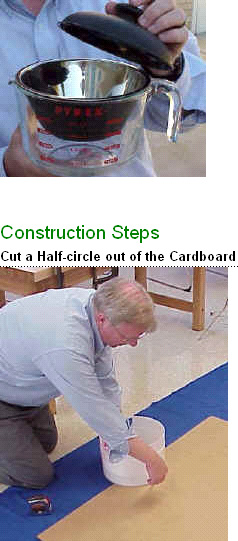 Cut a half circle out of the cardboard, along the bottom as shown below. When the funnel is formed, this becomes a full-circle and should be wide enough to go around your cooking pot. So for a 7" diameter cooking pot, the radius of the half-circle is 7". For a quart canning jar such as I use, I cut a 5" radius half-circle out of the cardboard. 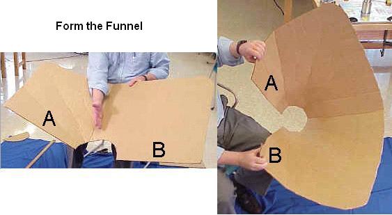 To form the funnel, you will bring side A towards side B, as shown in the figure. The aluminium foil must go on the INSIDE of the funnel. Do this slowly, helping the cardboard to the shape of a funnel by using one hand to form creases that radiate out from the half-circle. Work your way around the funnel, bending it in stages to form the funnel shape, until the two sides overlap and the half-circle forms a complete circle. The aluminium foil will go on the INSIDE of funnel. Open the funnel and lay it flat, "inside up", in preparation for the next step. Glue Foil to Cardboard 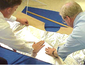 Apply glue or adhesive to the top (inner) surface of the cardboard, then quickly apply the aluminium foil on top of the glue, to affix the foil to the cardboard. Make sure the shiniest side of the foil is on top, since this becomes your reflective surface in the Funnel. I like to put just enough glue for one width of foil, so that the glue stays moist while the foil is applied. I also overlap strips of foil by about 1" ( or 2 cm). Try to smooth out the aluminium foil as much as you reasonably can, but small wrinkles won't make much difference. If cardboard is not available, one can simply dig a funnel-shaped hole in the ground and line it with a reflector, to make a fixed solar cooker for use at mid-day. Join side A to side B to keep the funnel together. 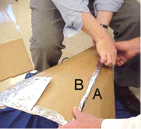 The easiest way to do this is to punch three holes in the cardboard that line up on side A and side B (see figure). Then put a metal brad through each hole and fasten by pulling apart the metal tines. Or you can use a nut-and-bolt to secure the two sides (A & B) together. Be creative here with what you have available. For example, by putting two holes about a thumb-width apart, you can put a string, twine, small rope, wire or twist-tie in one hole and out the other, and tie together. When A and B are connected together, you will have a "funnel with two wings". The wings could be cut off, but these help to gather more sunlight, so I leave them on. Tape or glue a piece of aluminium foil across the hole at the bottom of the funnel, with shiny side in. This completes assembly of your solar funnel cooker. For stability, place the funnel inside a cardboard or other box to provide support. For long-term applications, one may wish to dig a hole in the ground to hold the Funnel against strong winds. Final Steps At this stage, you are ready to put food items or water into the cooking vessel or jar, and put the lid on securely. (See instructions on food cooking times, to follow). Place a wooden block in the INSIDE bottom of the cooking bag. I use a piece of 2” x 4” board which is cut into a square nominally 4" x 4" by 2" thick. Then place the cooking vessel containing the food or water on top of the wooden block, inside the bag. Next, gather the top of the bag in your fingers and blow air into the bag, to inflate it. This will form a small "greenhouse" around the cooking vessel, to trap much of the heat inside. Close off the bag with a tight twist tie or wire. Important: the bag should not touch the sides or lid of the cooking vessel. The bag may be called a "convection shield," slowing convection-cooling due to air currents. Place the entire bag and its contents inside the funnel near the bottom as shown in the Photographs. Place the Solar Funnel Cooker so that it Faces the Sun Remember: Sunlight can hurt the eyes: so please wear sunglasses when using a Solar Cooker! The Funnel Cooker is designed so that the hot region is deep down inside the funnel, out of harm's way. 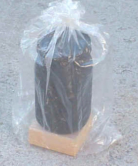 Put the Solar Funnel Cooker in the sun pointing towards the sun, so that it captures as much sunlight as possible. The design of the funnel allows it to collect solar energy for about an hour without needing to be re-positioned. For longer cooking times, readjust the position of the funnel to follow the sun's path. In the Northern Hemisphere, it helps to put the Solar Funnel Cooker in front of a south-facing wall or window as this reflects additional sunlight into the funnel. A reflective wall is most important in locations farther from the equator and in winter. In the Southern Hemisphere, put the Solar Funnel Cooker in front of a North-facing wall or window to reflect additional sunlight into your cooker. After Cooking Remember that the cooking vessel will be very hot: so use cooking pads or gloves when handling it! If you are heating water in a canning jar, you may notice that the water is boiling when the lid is first removed - it gets very hot! Open the plastic cooking bag by removing the twist-tie. Using gloves or a thick cloth, lift the vessel out of the bag and place it on the ground or table. Carefully open the vessel and check the food, to make sure it has finished cooking. Let the hot food cool before eating. Helpful Hints Avoid leaving fingerprints and smudges on the inside surface of the cooker. Keep the inner surface clean and shiny by wiping occasionally with a wet towel. This will keep the Solar Funnel Cooker working at its best. If your funnel gets out-of-round, it can be put back into a circular shape by attaching a rope or string between opposite sides which need to be brought closer together. For long-term applications, a hole in the ground will hold the Funnel Cooker securely against winds. Bring the funnel inside or cover it during rain storms. The lids can be used over and over. We have had some trouble with the rubber on some new canning-jar lids becoming soft and "sticky." "Ball canning lids" do not usually have this problem. Running new lids through very hot water before the first use seems to help. The lids can be used over and over if they are not bent too badly when opened (pry off lid carefully). The jar can be suspended near the bottom of the funnel using fishing line or string (etc.), instead of placing the jar on a block of wood. A plastic bag is placed around the jar with air puffed inside, as usual, to trap the heat. The suspension method allows sunlight to strike all surfaces of the jar, all around, so that heats faster and more evenly. This suspension method is crucial for use in winter months. Adjust the funnel to put as much sunlight onto the cooking jar as possible. Look at the jar to check where the sunlight is hitting, and to be sure the bottom is not in the shadows. For long cooking times (over about an hour), readjust the position of the funnel to follow the sun's path. During winter months, when the sun is low on the horizon (e.g., in North America), it is helpful to lay the funnel on its side, facing the sun. 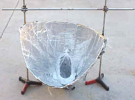 Tests in Utah I have personally used the Solar Funnel Cooker to cook lunches over many weeks. My favourite foods to cook are potatoes (cut into logs or slices) and carrot slices. Vegetables cook slowly in their own juices and taste delicious. I also make rice, melted cheese sandwiches, and even bread in the Solar Funnel Cooker. I usually put the food out around 11:30 and let it cook until 12:45 or 1 pm, just to be sure that it has time to cook. I've never had any food burn in this cooker. I have also cooked food in the mountains, at an altitude of around 8,300 feet. If anything, the food cooked faster there - the sunlight passes through less atmosphere at high altitudes. I find that people are surprised that the sun alone can actually cook food. And they are further pleasantly surprised at the rich flavours in the foods which cook slowly in the sun. This inexpensive device does it! Students at Brigham Young University have performed numerous tests on the Solar Funnel Cooker along with other cookers. We have consistently found much faster cooking using the Solar Funnel Cooker. The efficiency/cost ratio is higher than any other solar cooking device we have found to date. Mr. Hullinger also performed studies of transmissivity, reflectivity and absorptivity of alternate materials which could be used in the Solar Funnel Cooker. While there are better materials, such as solar-selective absorbers, our goal has been to keep the cost of the Solar Cooker as low as possible, while maintaining safety as a first priority. Tests in Bolivia The BYU Benson Institute organised tests between the Solar Funnel Cooker and the "old-fashioned" solar box oven. The solar box oven cost about $70 and was made mostly of cardboard. It took nearly two hours just to reach water pasteurisation temperature. The Bolivian report notes that "food gets cold every time the pots are taken from and into the oven." The solar box oven failed even to cook boiled eggs. (More expensive box cookers would hopefully work better.)  An aluminised-mylar Solar Funnel Cooker was also tested in Bolivia, during the Bolivian winter. Water pasteurisation temperature was reached in 50 minutes, boiled eggs cooked in 70 minutes, and rice cooked in 75 minutes. The Bolivian people were pleased by the performance. So were we! (La Paz, Bolivia, August, 1996). I also donated two dozen solar funnel cookers for people in Guatemala. These were taken there by a group of doctors going there for humanitarian service. The people there also liked the idea of cooking with the sun's free energy. For an aluminised-Mylar Solar Funnel Cooker kit, please contact CRM (licensed manufacturer) at +1 (801) 292-9210. Water and Milk Pasteurisiation Contaminated drinking water or milk kills thousands of people each day, especially children. The World Health Organisation reports that 80% of illnesses in the world are spread through contaminated water. Studies show that heating water to about 65º - 70º C (150º F) is sufficient to kill coliform bacteria, rotaviruses, enteroviruses and even Giardia. This is called pasteurisation. Pasteurisation depends on how hot and how long water is heated. But how do you know if the water got hot enough? You could use a thermometer, but this would add to the cost, of course. When steam leaves the canning jar (with lid on tight) and forms "dew" on the inside of the cooking bag, then the water is probably pasteurised to drink. (The goal is to heat to 160º Fahrenheit for at least six minutes.) With a stripe of black paint scraped off the jar, one can look through the bag and into the jar and see when the water is boiling - then it is safe for sure. Think of all the lives that can be saved simply by pasteurising water using a simple Solar Cooker! Safety Safety was my first concern in designing the Solar Funnel Cooker, then came low cost and effectiveness. But any time you have heat you need to take some precautions.
Cooking with the Solar Funnel Cooker What do you cook in a crock pot or moderate-temperature oven? The same foods will cook about the same in the Solar Funnel Cooker - without burning. The charts below give approximate summer cooking times. The solar cooker works best when the UV index is 7 or higher (Sun high overhead, few clouds). Cooking times are approximate. Increase cooking times for partly-cloudy days, sun not overhead (e.g., wintertime) or for more than about 3 cups of food in the cooking jar. Stirring is not necessary for most foods. Food generally will not burn in the solar cooker. Vegetables (Potatoes, carrots, squash, beets, asparagus, etc.) Preparation: No need to add water if fresh. Cut into slices or "logs" to ensure uniform cooking. Corn will cook fine with or without the cob. Cooking Time: About 1.5 hours Cereals and Grains (Rice, wheat, barley, oats, millet, etc.) Preparation: Mix 2 parts water to every 1 part grain. Amount may vary according to individual taste. Let soak for a few hours for faster cooking. To ensure uniform cooking, shake jar after 50 minutes. CAUTION: Jar will be hot. Use gloves or cooking pads. Cooking Time: 1.5-2 hours Pasta and Dehydrated Soups Preparation: First heat water to near boiling (50-70 minutes). Then add the pasta or soup mix. Stir or shake, and cook 15 additional minutes. Cooking Time: 65-85 minutes Beans Preparation: Let tough or dry beans soak overnight. Place in cooking jar with water. Cooking Time: 2-3 hours Eggs Preparation: No need to add water. Note: If cooked too long, egg whites may darken, but taste remains the same. Cooking Time: 1-1.5 hours, depending on desired yolk firmness. Meats (Chicken, beef, and fish) Preparation: No need to add water. Longer cooking makes the meat more tender. Cooking Times: Chicken: 1.5 hours cut up or 2.5 hours whole; Beef: 1.5 hours cut up or 2.5-3 hours for larger cuts; Fish: 1-1.5 hours Baking Preparation: Times vary based on amount of dough. Cooking Times: Breads: 1-1.5 hours; Biscuits: 1-1.5 hours; Cookies: 1 hour Roasted Nuts (Peanuts, almonds, pumpkin seed, etc.) Preparation: Place in jar. A little vegetable oil may be added if desired. Cooking Time: About 1.5 hours MRE's and pre-packaged foods Preparation: For foods in dark containers, simply place the container in the cooking bag in place of the black cooking jar. Cooking Times: Cooking time varies with the amount of food and darkness of package. How to Use the Solar Funnel as a Refrigerator/Cooler A university student (Jamie Winterton) and I were the first to demonstrate that the Brigham Young University Solar Funnel Cooker can be used - at night - as a refrigerator. Here is how this is done: The Solar Funnel Cooker is set-up just as you would during sun-light hours, with two exceptions:
During the day, the sun's rays are reflected on to the cooking vessel which becomes hot quickly. At night, heat from the vessel is radiated outward, towards empty space, which is very cold indeed (a "heat sink"). As a result, the cooking vessel now becomes a small refrigerator. We routinely achieve cooling of about 20º F (10º C) below ambient air temperature using this remarkably simple scheme. In September 1999, we placed two funnels out in the evening, with double-bagged jars inside. One jar was on a block of wood and the other was suspended in the funnel using fishing line. The temperature that evening (in Provo, Utah) was 78º F (25.5º C). Using a Radio Shack indoor/outdoor thermometer, a BYU student (Colter Paulson) measured the temperature inside the funnel and outside in the open air. He found that the temperature of the air inside the funnel dropped quickly by about 15º F (8º C), as its heat was radiated upwards in the clear sky. That night, the minimum outdoor air temperature measured was 47.5º F (8.6º C) - but the water in both jars had ICE. I invite others to try this, and please let me know if you get ice at 55 or even 60 degrees outside air temperature (minimum at night). A black PVC container may work even better than a black-painted jar, since PVC is a good infrared radiator - these matters are still being studied. I would like to see the "Funnel Refrigerator" tried in desert climates, especially where freezing temperatures are rarely reached. It should be possible in this way to cheaply make ice for Hutus in Rwanda and for aborigines in Australia, without using any electricity or other modern "tricks." We are in effect bringing some of the cold of space to a little corner on earth. Please let me know how this works for you. Conclusion: Why We Need Solar Cookers The BYU Funnel Cooker/Cooler can:
The burden for gathering the fuel wood and cooking falls mainly on women and children. Joseph Kiai reports : From Dadaab, Kenya: "Women who can't afford to buy wood start at 4 am to go collecting and return about noon... They do this twice a week to get fuel for cooking... The rapes are averaging one per week." From Belize: "Many times the women have to go into the forest dragging their small children when they go to look for wood. It is a special hardship for pregnant and nursing mothers to chop and drag trees back to the village... they are exposed to venomous snakes and clouds of mosquitoes." And the forests are dwindling in many areas. Edwin Dobbs noted in Audubon Magazine, Nov. 1992, "The world can choose sunlight or further deforestation, solar cooking or widespread starvation..." Americans should be prepared for emergencies, incident to power failures. A Mormon pioneer noted in her journal: "We were now following in their trail travelling up the Platte River. Timber was sometimes very scarce and hard to get. We managed to do our cooking with what little we could gather up..." (Eliza R. Snow) Now there's someone who needed a light-weight Solar Cooker! Here's another reason to use a solar cooker. Many people in developing countries look to see what's being done in America. I'm told that if Americans are using something, then they will want to try it, too. The more people there are cooking with the sun, the more others will want to join in. A good way to spread this technology is to encourage small local industries or families to make these simple yet reliable solar cookers for others at low cost. I've used this cooker for three summers and I enjoy it. Cooking and making ice with the funnel cooker/cooler will permit a significant change in lifestyle. If you think about it, this could help a lot of people. The BYU Solar Funnel Cooker uses the glorious sunshine -- and the energy of the sun is a free gift from God for all to use! Answers to commonly-asked questions Will the cooker work in winter (in the United States)? As the sun moves closer to the southern horizon in the winter, the solar cooker is naturally less effective. A good measure of the solar intensity is the “UV index” which is often reported with the weather. When the ultraviolet or UV index is 7 or above – common in summer months – the solar cooker works very well. In Salt Lake City in October, the UV index was reported to be 3.5 on a sunny day. We were able to boil water in the Solar Funnel Cooker during this time, but we had to suspend the black jar in the funnel so that sunlight struck all sides. (We ran a fishing line under the screw-on lid, and looped the fishing line over a rod above the funnel. As usual, a plastic bag was placed around the jar, and this was closed at the top to let the fishing line out for suspending the jar.) The solar “minimum” for the northern hemisphere occurs on winter solstice, about December 21st each year. The solar “maximum” occurs six months later, June 21st. Solar cooking works best from about 20th March to 1st October in the north. If people try to cook with the sun for the first time outside of this time window, they should not be discouraged. Try again when the sun is more directly overhead. One may also suspend the jar in the funnel, which will make cooking faster any time of the year. It is interesting to note that most developing countries are located near the equator where the sun is nearly directly overhead all the time. Solar Cookers will then serve year-round, as long as the sun is shining, for these fortunate people. They may be the first to apply fusion energy (of the sun) on a large scale. They may also accomplish this without the expensive infrastructure of electrical power grids that we take for granted in America. How do you cook bread in a jar? I have cooked bread by simply putting dough in the bottom of the jar and placing it in the funnel in the usual way. Rising and baking took place inside the jar in about an hour (during summer). One should put vegetable oil inside the jar before cooking to make removal of the bread easier. I would also suggest that using a 2-quart wide-mouth canning jar instead of a 1-quart jar would make baking a loaf of bread easier. What is the optimum “opening angle” for the funnel cooker? A graduate student at Brigham Young University did a calculus calculation to assess the best shape or opening angle for the Solar Funnel. Jeannette Lawler assumed that the best operation would occur when the sun’s rays bounced no more than once before hitting the cooking jar, while keeping the opening angle as large as possible to admit more sunlight. (Some sunlight is lost each time the light reflects from the shiny surface. If the sunlight misses on the first bounce, it can bounce again and again until being absorbed by the black bottle). She set up an approximate equation for this situation, took the calculus derivative with respect to the opening angle and set the derivative equal to zero. Optimising in this way, she found that the optimum opening angle is about 45 degrees, when the funnel is pointed directly towards the sun. But we don’t want to have to “track the sun” by turning the funnel every few minutes. The sun moves (apparently) 360 degrees in 24 hours, or about 15 degrees per hour. So we finally chose a 60-degree opening angle so that the cooker is effective for about 1.2 hours. This turned out to be long enough to cook most vegetables, breads, boil water, etc. with the Solar Funnel Cooker. We also used a laser pointer to simulate sun rays entering the funnel at different angles, and found that the 60-degree cone was quite effective in concentrating the rays at the bottom of the funnel where the cooking jar sits. For questions regarding the complete Solar Funnel Cooker kit using aluminised Mylar and a jar for the cooking vessel, please contact CRM at +1 (801) 292-9210. Tests of the Solar Funnel and Bowl Cookers in 2001 Christopher McMillan and Steven E. Jones Brigham Young University Introduction With an increase in population and a decrease in available fuels such as wood and coal in developing countries, the need for alternative cooking methods has increased. Solar cookers are an alternative to conventional methods such as wood-fires and coal-fires. They provide usable heat for cooking and pasteurising water, without the harmful side effects such as smoke inhalation that non-renewable sources create. In many countries such as Haiti, Bolivia and Kenya, the need for cheap, effective, and safe cooking methods has increased due to poverty and deforestation. Solar cookers are ideal because they rely on the sun’s free energy which is abundant in many of the world’s poorest countries. Though there are good designs, more testing and improvement is desirable. There are three areas of comparison that were focused on during the course of the study. The first area of comparison is in the reflective material used. The original material is a mirror-finished aluminium Mylar. Due to the mirror finish, the reflection light is very bright and can be difficult to work over when cooking. An alternative material is a matt-finish Mylar. This material diffuses the sunlight and is not as harsh on the eyes as is the mirrored finish. The second area of concentration is on the method of containing the air that surrounds the cooker so that the cooker is kept from being cooled by convection currents. A common method is to use a clear plastic oven-safe bag around the cooking vessel. However, this method is rather tedious and awkward to use, and such bags are rarely available in developing countries. Another technique is to use a disk or window make out of a clear plastic or glass. This makes the cooker easier to use. 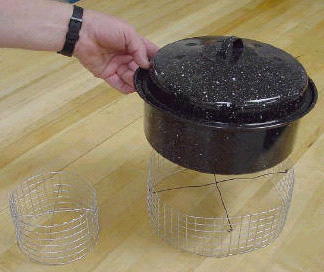 The third main area of focus is in the cooking containers used. The present cooking vessel for the Solar Funnel Cooker is a black-painted canning jar. This method is also tedious and awkward. The canning jars can be hard to clean, and they can break. Design changes are tested that would allow people to use their own cookware. This too would make the cooker more convenient to use. The fourth area of testing pitted the wooden block support which we have been using for years against a rabbit-wire support. A rabbit-wire cylinder holds the cooking vessel up off the bottom of the cooker, and allows sunlight to strike essentially all surfaces of the cooking vessel, including the bottom. The effectiveness of these methods is tested and compared both qualitatively and quantitatively. In addition to acquiring temperature-rise versus time data, we also cooked numerous meals in the solar cookers so as to get hands-on experience with cooking. Several students participated in these cooking tests. Cooker Designs: Several solar cooker designs were used during these tests. The Solar Funnel Cooker was the main cooker tested. A Solar CooKit and a bowl-shaped variation of the Solar Funnel Cooker were also tested. Most experiments were comparative tests between the various designs, and the cooker set-up was varied from test to test. The basic design of the Solar Funnel Cooker is a funnel-shaped aluminium Mylar collector. A highly reflective material is necessary to collect and concentrate the sun’s rays. The funnel walls are at a 60 degree angle (with respect to the horizontal) since this collects sunlight for a two hour time period without requiring re-orientation to follow the sun. Due to the way the Mylar sheets are cut and folded, a pair of wings on opposite ends of the funnel is formed. The wings increase the collector size and create an elliptical shape at top. At the tips of the wings, the cooker stands about 20 inches high and has a diameter of about 28 inches. At the top, along the minor axis of the elliptical funnel, the cooker stands about 15 inches high, and has a diameter of about 20 inches. Since the Aluminium Mylar does not support itself well, a nine inch diameter by five inch high bucket is used to support the funnel. 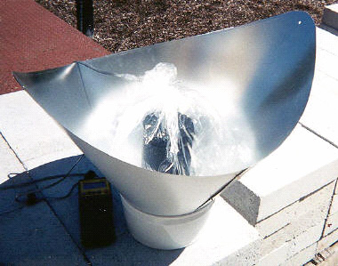 The cooking container primarily tested is a glass canning jar that has been painted flat black. The black paint allows the jar to absorb the sun’s rays. The canning jar works well due to the added pressure-cooker effect caused by the rubber ring on the inside of the lid. A black-enamel pot and a black-painted stainless steel canister were also used. We found immediately that raising the vessel off the bottom of the cooker using a rabbit-wire stand provided more rapid and even heating than the wooden block used previously. Placing the jar or pot on a wire stand allows as much reflected light onto the cooking vessel as possible. This allows even the bottom of the cooking container to absorb thermal energy that is reflected off the lower portion of the funnel. Two methods of closing the cookers off from convection currents were used. It is important to keep the air that surrounds the container from circulating, thus keeping the cooking container from being cooled by convection currents or breezes. This first method used was to enclose the cooking vessel and wire stand in a clear plastic bag, such as a heat resistant Reynolds Oven Bag. It is important to make sure that the bag is not touching the cooking vessel, so once the vessel is placed into the clear bag, air is blown into the bag and the bag is tied off. This is the most common method used for solar panel cookers, such as the Solar CooKit, because of the bags’ ability to withstand the temperatures attained in these types of cookers. But these bags tear rather easily and they are not readily available in developing countries and must be imported. The second method of closing off the cooking vessel from convection currents, designed by Dr. Jones, is to place a clear plastic disk down into the funnel above the cooking vessel. The funnel used in the test was a conventional-shaped funnel that was constructed out of thin sheet metal and aluminium-foil lined for better reflectivity. The diameter of this funnel is about 30 inches at the top, and it stands about 16 inches high. The walls also form about a 60 degree angle with respect to the horizontal. This funnel was designed to hold a larger cooking container such as a pot. The diameter of the plastic disk is large enough that the disk does not touch the top of the container. For the experiments that tested this method, a one-sixteenth inch (1.6 mm) thick Lexan disk was used. Data Collection To collect the temperatures as a function of time, a Texas Instruments Calculator Based Laboratory (CBL) was used. This portable interface is capable of recording real-time data from multiple channels. The data were downloaded into a graphing calculator, where they can be analysed and graphed immediately. From the calculator, the data can be transferred to a computer spreadsheet such as Microsoft Excel for further analysis. Due to the nature of these experiments and the low cost to purchase the CBL, this is an ideal data collector to use. A graphing calculator was used to program the CBL and to tell it what data to collect, how many points to collect, and the time period between data points collected. Since the CBL does not have any internal programs for data collection, a program must be written into the graphing calculator. There are ready-made programs that can be uploaded into the calculator, or a custom program can be made to fit the needs of the test. The program that the CBL used allowed multiple thermocouples to collect data simultaneously. To ensure that the thermocouples were calibrated against each other, both were run on the same constant temperature sample in very close proximity. Both temperature probes agreed to within 0.21oC of each other. For these experiments, this temperature difference was considered to be acceptable. Procedure Each experiment was conducted on the campus of Brigham Young University during mid-day, usually between 11:00 am and 2:00 pm to ensure that the sun was close to being directly over-head. This allowed as much sun light as possible to enter the solar collector. Each experiment included several steps, as listed below. Before each experiment was set up, the volume of the water and the mass of the container were measured and recorded. The heat capacity of the water and the container were also found. The area of the cooker perpendicular to the sun’s rays was also measured. To collect temperature data using thermocouple probes, small holes were drilled into the top of the canning jar and stainless steel canister lids. The jar and canister were both painted ultra-flat black to absorb as much of the sun’s energy as possible. On the morning of each test, the designated volume of water was measured out and poured into the cooking vessel. This volume ranged from 0.6 litre for one-quart jars, to 1.2 litters for half-gallon canning jars. For simultaneous testing, the same amount of water was poured into each container. The temperature probes were wired through the holes in the lids of the containers and secured about 13 mm into the water. For comparative tests, the probes were placed the same depth into the water to ensure that the probes did not read different measurements due to depth-related temperature differences within the containers. To enable later analysis; the time, ambient temperature, and solar irradiance were also noted and recorded. These numbers gave a reference point for each test. Each cooker that was to be tested was then completely set up. The temperature probes were secured through the lids, and the jar was placed into the clear oven bag – supported by a wire cage. Each bag was inflated so that no part of the bag touched the sides or top of the cooking container. The cord from the thermocouple to the CBL was passed through the top of the bag, and the bag was tied off with a twist-tie. The test began once both cookers were completely ready and the CBL had been programmed. Care was taken to block the sun from radiating directly onto the cookers until both were ready to begin. This ensured that the water in both cookers started at very nearly the same temperature. Most tests were set up to collect one data point every four to five minutes, for up to two hours. This allowed the cooker temperatures to reach maxima and then remain at a nearly constant temperature. Once a test was complete, the cooker was disassembled and the data downloaded into the graphing calculator. Though the graphing calculator does allow analysis, a spread sheet such as Microsoft Excel is easier to use. Thus, the data from each test were downloaded from the calculator into Microsoft Excel. The elapsed time (in seconds) and the corresponding temperatures were listed next to each other. A graph of temperature versus time was made, with the Time being the horizontal axis for each test. For comparative tests, the Temperature versus Time data for both cookers was plotted on the same graph. As a reference, a trend-line was fitted to the linear portion of the graph, along with the linear regression and the coefficient of correlation (R2). It is important to have a coefficient of correlation close to one, as this is how close the linear regression fits the data. In a separate column, the temperatures were again listed, however only from 30oC to 70oC. The change in temperature for every ten or twelve minutes was found and logged next to the temperature column. The power output (in Watts) of each cooker could then be calculated. To calculate the power output of the cookers for each specific test, the mass of the water and of the container were both measured. Though the thermal energy content of the container was relatively small compared to that of water (due to the large heat capacity of water), it was important to add it into the calculation. Also, since several different containers were compared, the energy content of the container was important. The power is found by:  The power is found in Watts. A power output for each change in temperature for the time interval is calculated and logged next to the T column. Since there are uncertainties in all of the measurements, it is important to include the error in each power output. To do this, the error in the water’s and container’s measurements is taken into consideration. The error is found by:  Where ±dP is the total error in the calculated error, dmw and dmc are the error in the mass of the water and container respectively, delta-Tp is the error in the temperature difference, and delta-t is the error in the time interval. This simplifies to:  The error was found only for the average change in temperature, rather than for each individual temperature measurement. Since the power output is dependant on the amount of energy coming in from the sun, the cooker efficiency is a good factor to calculate. To find the efficiency, the total amount of local solar radiation must be known. This should be given in watts per square metre, so that the input wattage can be found. To find the power coming in, the area of the cooker perpendicular to the sun’s rays was multiplied by the solar radiation to give the amount of power that was being collected by the cooker. Since the Solar Funnel is able to be kept on track with the sun, and since the tests were done during mid-day, it was not necessary to calculate any angles. The efficiency is simply the power output divided by the power input. The solar radiation for each test was supplied by the Department of Physics and Astronomy weather station at Brigham Young University in Provo, UT, where the tests took place. Results: Matt vs. Mirror: Several tests were conducted on the matt versus mirror finishes. In each test, the matt finish outperformed the mirror finish. On 27 July, 2001, a matt funnel and a mirror funnel were simultaneously tested with 650 cc of water. The average power output for the mirror finish was 46.4 W ± 1.7 W, while the matt funnel put out an average of 59.4 W ± 2.1 W. The efficiency of the mirror funnel was 15.8%, while the matt was 20.2% efficient. The following graph shows the temperatures reached by the matt and mirror funnels.  Channel 1 (Ch1) was the mirror finish, and channel 2 (Ch2) was the matt finish. This shows that both funnels peaked at about the same temperature: 97oC (207oF). The matt funnel peaked in about 76 minutes, whereas the mirror funnel peaked in 96 minutes, twenty minutes later. Though this perhaps a tolerable time difference for actual cooking, it is substantial. Every matt vs. mirror test performed in a similar way. These results are due to the way the matt funnel reflects the sun’s rays. The mirror finish seems to focus a strip of light onto the cooking vessel more than the matt finish does. As a result, the matt finish diffuses the light more and the cooker is heated more uniformly. This is good, since the matt finish is easier to work with, delivering much less glare to the eyes. The following graph shows the temperature rise with time for a Solar CooKit:  Comparing the two graphs above, we find that the Solar CoolKit performed very well, comparable to the Funnel Cooker. We should note that in both cases, we used a canning jar (pressurised) supported by a wire stand. We found that the wire stand improves the performance of the Solar CooKit significantly and hope that this support stand will be used in countries where the Solar CooKit is in use. In tests where the use of the clear plastic disk was tested against the oven-bag, an aluminium pot was used in the disk-set-up. In these tests, the cooker with an oven bag outperformed the cooker using a plastic disk. On 10 August, 2001, a test was run which compared the disk/pot set-up against the oven-bag/jar set-up. Both cookers follow similar heating paths with time, but the oven-bag/jar did slightly better. Due to the higher mass of the jar compared to the mass of the aluminium pot, and the much higher heat capacity of the water, the average power output for the oven-bag/jar was 39.8 ± 1.4 W, while the disk/pot put out 30.3 W ± 1.2 W. The efficiency of the oven-bag/jar was 14.7% and the efficiency of the disk/pot set-up was 10.4% for this test. This is also partly due to the pressure-cooker effect that the canning jar produces. Though this is a considerable efficiency difference, the disk/pot set-up did very well in subjective tests where food was actually cooked and tasted. In all cases where the disk/pot set-up was used to cook food, the food cooked in about the same amount of time. The ease of the disk/pot set-up is also an important consideration. Overall, in tests where food was cooked, the disk/pot set-up was preferred over the oven-bag/jar set-up. Conclusions: As many countries are depleting their natural resources due to increased population and the resulting deforestation, methods other than burning wood are needed to cook food and pasteurise water. Solar cookers provide a sustainable technology that relies on the sun’s free energy. We report several advances to make them better. The need for cheap and effective solar cookers is very great and growing. The Solar Funnel Cooker has been designed to meet the growing need by being inexpensive and effective. We determined that the Solar CooKit was nearly as effective when a rabbit-wire stand was used to support the cooking vessel. By collecting time vs. temperature data, quantitative analysis has been done. This analysis approach is useful for further development of the cookers. Several areas of research were explored in 2001. Two finishes were tested for the reflector, a matt finish and a mirror finish. The benefits of the matt over the mirror finish are: 1) The matt finish is easier to work over because the sun’s glaring reflection is diffused, and 2) the matt finish out-performs the mirror finish in temperature vs. time tests. The method of closing off the cooker from convection current was tested and compared with an alternative method – a clear plastic disk. The use of a pot rather that a canning jar was also tested. Though the present oven-bag/jar method does outperform the disk/pot method, the disk/pot method is easier to use and seems to be nearly as efficient. Finally, we showed that a wire-mesh stand is a considerable improvement over the use of a wooden block or other opaque stand for the cooking vessel. We join with our fellow researchers around the world in pursuing further development of solar cookers, particularly to benefit people in developing countries. References: [1]. Jones, Steven E. et al., BYU. [2]. Wattenberg, Frank. Montana State University. 1996. [2]. Wattenberg, Frank. Montana State University. 1996.Error! Reference source not found.  The main purpose of solar cookers is to change sunlight into heat which is then used to cook foods. We are all familiar with how successful solar cookers are at cooking and baking a wide variety of foods. In this article I want to consider using the heat in solar cookers for purposes other than cooking. My main focus will be solar water pasteurisation, which can complement solar cooking and address critical health problems in many developing countries. The majority of diseases in developing countries today are infectious diseases caused by bacteria, viruses, and other microbes which are shed in human faeces and polluted water which people use for drinking or washing. When people drink the live microbes, they can multiply, cause disease, and be shed in faeces into water, continuing the cycle of disease transmission. World-wide, unsafe water is a major problem. An estimated one billion people do not have access to safe water. It is estimated that diarrhoeal diseases that result from contaminated water kill about 2 million children and cause about 900 million episodes of illness each year. Boiling contaminated water How can infectious microbes in water be killed to make the water safe to drink? In the cities of developed countries this is often guaranteed by chlorination of water after it has been filtered. In developing countries, however, city water systems are less reliable, and water from streams, rivers and some wells may be contaminated with human faeces and pose a health threat. For the billion people who do not have safe water to drink, what recommendation do public health officials offer? The only major recommendation is to boil the water, sometimes for up to 10 minutes. It has been known since the time of Louis Pasteur 130 years ago that heat of boiling is very effective at killing all microbes which cause disease in milk and water. If contaminated water could be made safe for drinking by boiling, why is boiling not uniformly practised? There seem to be five major reasons:
If wood, charcoal, or dung is used as fuel for boiling water, the smoke creates a health hazard, as it does all the time with cooking. It is estimated that 400 to 700 million people, mainly women, suffer health problems from this indoor air pollution. As a microbiologist, I have always been perplexed as to why boiling is recommended, when this is heat far in excess of that which is necessary to kill infectious microbes in water. I presume the reason boiling is recommended is to make sure that lethal temperatures have been reached, since unless one has a thermometer it is difficult to tell what temperature heated water has reached until a roaring boil is reached. Everyone is familiar with the process of milk pasteurisation. This is a heating process which is sufficient to kill the most heat resistant disease causing microbes in milk, such as the bacteria which cause tuberculosis, undulant fever, streptococcal infections and Salmonellosis. What temperatures are used to pasteurise milk? Most milk is pasteurised at 71.7o C (161o F) for only 15 seconds. Alternatively, 30 minutes at 62.8o C (145o F) can also pasteurise milk. Some bacteria are heat resistant and can survive pasteurisation, but these bacteria do not cause disease in people. They can, however, spoil the milk, so pasteurised milk is kept refrigerated. There are some different disease microbes found in water, but they are not unusually heat resistant. The most common causes of water diseases, and their heat sensitivity, are presented in Table 1. The most common causes of acute diarrhoea among children in developing countries are the bacteria Escherichia coli and Shigelia SD. and the Rotavirus group of viruses. These are rapidly killed at temperatures of 60o C or greater. Solar water pasteurisation As water heats in a solar cooker, temperatures of 56o C and above start killing disease-causing microbes. A graduate student of mine, David Ciochetti, investigated this for his master's thesis in 1983, and concluded that heating water to 66o C in a solar cooker will provide enough heat to pasteurise the water and kill all disease causing microbes. The fact that water can be made safe to drink by heating it to this lower temperature - only 66o C - instead of 100o C (boiling) presents a real opportunity for addressing contaminated water in developing countries. Testing water for faecal contamination How can one readily determine if the water from a well, pump, stream, etc. is safe to drink? The common procedure is to test the water for bacterial indicators of faecal pollution. There are two groups of indicators which are used. The first is the coliform bacteria which are used as indicators in developed countries where water is chlorinated. Coliform bacteria may come from faeces or from plants. Among the coliform bacteria is the second indicator, Escherichia coli. This bacterium is present in large numbers in human faeces (approximately 100,000,000 per gram of faeces) and that of other mammals. This is the main indicator used if water is not chlorinated. A water source containing 100 E. coli per 100 ccs poses a substantial risk of disease. The standard method of testing water for the presence of coliforms and E. coli requires trained personnel and a good laboratory facility or field unit which are usually not present in developing countries. Thus, water supplies are almost never tested. A new approach to testing in developing countries In 1987, the Colilert MPM Test (CLT) was introduced as the first method which used a defined substrate technology to simultaneously detect coliforms and E. coli. The CLT comes as dry chemicals in test tubes containing two indicator nutrients: one for coliforms and one for E. coli. The CLT involves adding 10 ml of water to a tube, shaking to dissolve the chemicals, and incubating at body temperature for 24 hours. I prefer incubating tubes under my belt against my body. At night I sleep on my back and use night clothes to hold the tubes against my body. If no coliform bacteria are present, the water will remain clear. However, if one or more coliforms are present in the water, after 24 hours their growth will metabolise ONPG and the water will change in colour from clear to yellow (resembling urine). If E. coli is among the coliform bacteria present, it will metabolise MUG and the tube will fluoresce blue when a battery-operated, long-wave ultraviolet light shines on it, indicating a serious health hazard. I have invited participants at solar box cooker workshops in Sierra Leone, Mali, Mauritania, and Nepal to test their home water supplies with CLT. One hundred and twenty participants brought in samples. In all four countries, whether the water was from urban or rural areas, the majority of samples contained coliforms, and at least half of these had E. coli present. Bacteriological testing of the ONPG and MUG positive tubes brought back from Mali and Mauritania verified the presence of coliforms/E. coli in approximately 95% of the samples. It is likely that soon the Colilert MPN test will be modified so that the test for E. coli will not require an ultraviolet light, and the tube will turn a different colour than yellow if E coli is present. This will make the test less expensive and easier to widely use in developing countries to assess water sources. Effect of safe water on diarrhoea in children What would be the effect if contaminated water could be made safe for drinking by pasteurisation or boiling? One estimate predicts that if in the Philippines, families at present using moderately contaminated wells (100 E. coli per 100 ml) were able to use a high-quality water source, diarrhoea among their children would be reduced by over 30%. Thus, if water which caused a MUG (+) test were solar pasteurised so it would be clear, this would help reduce the chance of diarrhoea, especially in children. Water pasteurisation indicator  How can one determine if heated water has reached 65o C? In 1988, Dr. Fred Barrett (USDA, retired) developed the prototype for the Water Pasteurisation Indicator (WAPI). In 1992, Dale Andreatta, a graduate engineering student at the University of California, Berkeley, developed the current WAPI. The WAPI is a polycarbonate tube, sealed at both ends, partially filled with a soybean fat which melts at 69o C ("MYVEROL" 18-06K, Eastman Kodak Co., Kingsport, TN 37662). The WAPI is placed inside a water container with the fat at the top of the tube. A washer will keep the WAPI on the bottom of the container, which heats the slowest in a solar box cooker. If heat from the water melts the fat, the fat will move to the bottom of the WAPI, indicating water has been pasteurised. If the fat is still at the top of the tube, the water has not been pasteurised. The WAPI is reusable. After the fat cools and becomes solid on the bottom, the fish line string is pulled to the other end and the washer slides to the bottom, which places the fat at the top of the tube. Another pasteurisation indicator has been developed by Roland Saye which is based on expansion of a bi-metal disc which is housed in a plastic container. This also shows promise and is in the early testing stages. The WAPI could be useful immediately for people who currently boil water to make it safe to drink. The WAPI will indicate clearly when a safe temperature has been reached, and will save much fuel which is currently is being wasted by excessive heating. 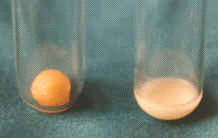 [Editor's note: Using Beeswax & Carnauba Wax to Indicate Temperature: In SBJ #15 we discussed using beeswax, which melts at a relatively low 62o C, as an indicator of pasteurisation. We have now found that mixing a small amount of carnauba was with the beeswax (~1:5 ratio) raises the melting temperature of the beeswax to 70o - 75o C. Carnauba wax is a product of Brazil and can be bought in the US at woodworking supply stores. Further testing needs to be done to confirm that the melting point remains the same after repeated re-melting. Different strategies for solar water pasteurisation The solar box cooker was first used to pasteurise water. David Ciochetti built a deep-dish solar box cooker to hold several gallons of water. At this time of the year in Sacramento, three gallons could be pasteurised on our typical sunny days. Dale Andreatta and Derek Yegian of the University of California. Berkeley, have developed creative ways to greatly increase the quantity of water which can be pasteurised, as we will hear about at this conference. I am also excited about the possibility of pasteurising water using the simple solar panel cookers. By enclosing a dark water container in a polyester bag to create an insulating air space, and by using lots of reflectors to bounce light onto the jar, it is possible to pasteurise useful amounts of water with a simple system. It takes about four hours for me to pasteurise a gallon of water in the summer with the system I am using. Solar panel cookers open up enormous possibilities for heating water not only for pasteurisation, but also for making coffee and tea, which are quite popular in some developing countries. The heated water can also be kept hot for a long time by placing it in its bag inside an insulated box. In the insulated container I use, a gallon of 80o C water will be approximately 55o C after 14 hours. Water at a temperature of 55o C will be about 40o C after 14 hours, ideal for washing/shaving in the morning. I will close with some advice from the most famous microbiologist, who pioneered the use of vaccinations in the 1890s: Louis Pasteur. When he was asked the secret of his success, he responded that above all else, it was persistence. I will add that you need good data to be persistent about, and we certainly have that with solar cookers; the work in Sacramento, Bolivia, Nepal, Mali, Guatemala, and wherever else the sun shines. Continued overuse of fuel-wood is non-sustainable. We need to persist until the knowledge we have spreads and becomes common knowledge world-wide. For questions or comments contact Dr. Robert Metcalf at. Dr. Robert Metcalf 1324 43rd St. Sacramento, California 95819 USA. IDEXX Laboratories, Inc. makes the Colilert kit and is located at this address: IDEXX Laboratories, Inc. One IDEXX Drive Westbrook, ME 04092 USA Voice: (800) 321-0207 or (207) 856-0496 Fax: (207) 856-0630 Editor's Note: Testing Water in Developing Countries The Colilert system makes it possible to test water without the need for a laboratory. IDEXX Laboratories, the manufacturer, recommends that you use five test tubes for each sample. Bob Metcalf explains that five tubes would comprise 50 ml, which is the minimum sample size permitted by US law. This is an unrealistically high standard by which to judge the water in developing countries where you are examining water that is already being drunk, in spite of the fact that it may be making people sick. By using a single test tube (10 ml) there is a very small chance that your sample missed the small number of bacteria that might have been present. IDEXX Laboratories will also tell you that you need an incubator to achieve valid results. Again, Bob Metcalf tells us that all that is needed is to keep the tubes close to your body for 36 hours, since body temperature is the correct incubation temperature. What you are actually measuring in the test is the presence of 1) coliform bacteria, and 2) E. coli, a type of coliform bacteria that is largely found in faecal matter. A positive test for coliform bacteria might be due to coliform bacteria that has washed off of plant leaves , and thus be fairly innocuous. A positive test for E. coli, however, would indicate that any bacteriological contamination was from a faecal source, which might also contain Giardia, cholera, or other serious infectious microbes. This document is published as part of The Solar Cooking Archive. 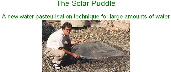 The lack of clean drinking water is a major health problem in the developing world. To reduce this health risk ways of producing clean water at an affordable cost are needed, and people need to be educated about germs and sanitation, lest they accidentally re-contaminate their clean drinking water. Recently, several of us at the University of California at Berkeley have attacked the first of these requirements. Previous issues of this newsletter have included stories about our water pasteurisation indicator and our flow-through water pasteurises based on a design by PAX World Service. In this article we describe a new low-cost device that pasteurises water. For those not familiar with the pasteurisation process, if water is heated to 149O F (65o C) for about 6 minutes all the germs, viruses, and parasites that cause disease in humans are killed, including cholera and hepatitis A and B. [Ed. We have reports from the field that at 145o F (63o C) in a solar puddle, bacterial growth might actually be increased. Since this temperature is very close to the minimum pasteurisation temperature mentioned in this article, we suggest that you heat the water to a higher temperature and perform tests before adopting a solar puddle as your method of pasteurisation]. This is similar to what is done with milk and other beverages. It is not necessary to boil the water as many people believe. Pasteurisation is not the only way to decontaminate drinking water, but pasteurisation is particularly easy to scale down so the initial cost is low. The new device is called a solar puddle, and it is essentially a puddle in a greenhouse. One form of the solar puddle is sketched in the figure below, though many variations are possible.  One begins by digging a shallow pit about 4 inches deep. The test device was a "family-size" unit, about 3.5 feet by 3.5 feet, but the puddle could be made larger or smaller. If the puddle is made larger there is more water to pasteurise, but there is also proportionately more sunshine collected. The pit is filled with 2 to 4 inches of solid insulation. We used wadded paper, but straw, grass, leaves, or twigs could be used. This layer of insulation should be made flat, except for a low spot in one corner of the puddle. Put a layer of clear plastic and then a layer of black plastic over the insulation with the edges of the plastic extending up and out of the pit. Two layers are used in case one develops a small leak. We used inexpensive polyethylene from a hardware store, though special UV stabilised plastic would last longer. Put in some water and flatten out the insulation so that the water depth is even to within about 0.5 inch throughout the puddle, except in the trough which should be about 1 inch deeper than the rest. Put in more water so that the average depth is 1 to 3 inches depending on how much sunshine is expected. A pasteurisation indicator (available from Solar Cookers International at 916/455-4499) should go in this trough since this is where the coolest water will collect. Put a layer of clear plastic over the water, again with the edges extending beyond the edges extending beyond the edges of the pit. Form an insulating air gap by putting one or more spacers on top of the third layer of plastic (large wads of paper will do) and putting down a fourth layer of plastic, which must also be clear. The thickness of the air gap should be 2 inches or more. Pile dirt or rocks on the edges of the plastic sheets to hold them down. The puddle is drained by siphoning the water out, placing the siphon in the trough and holding it down by a rock or weight. If the bottom of the puddle is flat, well over 90% of the water can be siphoned out. Once the puddle is built it would be used by adding water each day, either by folding back the top two layers of plastic in one corner and adding water by bucket, or by using a fill siphon. The fill siphon should NOT be the same siphon that is used to drain the puddle, as the fill siphon is re-contaminated each day, while the drain siphon MUST REMAIN CLEAN. Once in place the drain siphon should be left in place for the life of the puddle. The only expensive materials used to make the puddle are a pasteurisation indicator (about $2 for the size tested). All of these items are easily transportable, so the solar puddle might be an excellent option for a refugee camp if the expertise were available for setting them up. Many tests were done in the spring and summer of this year in Berkeley, California. On days with good sunshine the required temperature was achieved even with 17 gallons of water (2 1/2 inch depth). About 1 gallon is the minimum daily requirement per person, for drinking, brushing one's teeth, and dish washing. With thinner water layers higher temperatures can be reached. With 6 gallons (1 inch depth) 176o F was achieved on one day. The device seems to work even under conditions that are not ideal. Condensation in the top layer of plastic doesn't seem to be a problem, though if one gets a lot of condensation the top layer should be pulled back to let the condensation evaporate. Small holes in the top layers don't make much difference. The device works in wind, or if the bottom insulation is damp. Water temperature is uniform throughout the puddle to within 2o F. After some months the top plastic layers weaken under the combined effects of sun and heat and have to be replaced, but this can be minimised by avoiding hot spots. Another option would be to use a grade of plastic that is more resistant to sunlight. The two bottom layers of plastic tend to form tiny tears unless one is very careful in handling them, (that is why there are two layers on the bottom). A tiny hole may let a little water through and dampen the solid insulation, but this is not a big problem. There are many variations of the solar puddle. We've been able to put the top layer of plastic into a tent-like arrangement that sheds rain. This would be good in a place that gets frequent brief showers. Adding a second insulating layer of air makes the device work even better, though this adds the cost of an extra layer of plastic. As mentioned the device can cover a larger or smaller area if more or less water is desired. One could make a water heater by roughly tripling the amount of water so that the maximum temperature was only 120° F or so, and this water would stay warm well into the evening hours. This water wouldn't be pasteurised though. One could help solve the problem of dirty water vessels by putting drinking cups into the solar puddle and pasteurising them along with the water. The solar puddle could possibly cook foods like rice on an emergency basis, perhaps in a refugee camp. You can contact Dr. Dale Andreatta S. E. A. Inc. 7349 Worthington-Galena Rd. Columbus, OH 43085 (614) 888-4160 FAX (614) 885-8014 web link 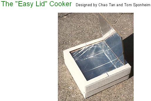 Although designs for cardboard cookers have become more simple, fitting a lid can still be difficult and time consuming. In this version, a lid is formed automatically from the outer box. Making the Base Take a large box and cut it in half as shown in Figure 1. Set one half aside to be used for the lid. The other half becomes the base.  Fold an extra cardboard piece so that it forms a liner around the inside of the base (see Figure 2).  Use the lid piece as shown in Figure 3 to mark a line around the liner.  Cut along this line, leaving the four tabs as shown in Figure 4.  Glue aluminium foil to the inside of the liner and to the bottom of the outer box inside. Set a smaller (inner) box into the opening formed by the liner until the flaps of the smaller box are horizontal and flush with the top of the liner (see Figure 5). Place some wads of newspaper between the two boxes for support.  Mark the underside of the flaps of the smaller box using the liner as a guide. Fold these flaps down to fit down around the top of the liner and tuck them into the space between the base and the liner (see Figure 6). Fold the tabs over and tuck them under the flaps of the inner box so that they obstruct the holes in the four corners (see Figure 6).  Now glue these pieces together in their present configuration. As the glue is drying, line the inside of the inner box with aluminium foil. Finishing the Lid Measure the width of the walls of the base and use these measurements to calculate where to make the cuts that form the reflector in Figure 7. Only cut on three sides. The reflector is folded up using the fourth side as a hinge. Glue plastic or glass in place on the underside of the lid. If you are using glass, sandwich the glass using extra strips of cardboard. Allow to dry.  Bend the ends of the wire as shown in Figure 7 and insert these into the corrugations on the lid and on the reflector to prop open the latter. Paint the sheet metal (or cardboard) piece black and place it into the inside of the oven. Improving Efficiency Glue thin strips of cardboard underneath the sheet metal (or cardboard) piece to elevate it off of the bottom of the oven slightly. Cut off the reflector and replace it with one that is as large as (or larger than) the entire lid. This reflects light into the oven more reliably. Turn the oven over and open the bottom flaps. Place one foiled cardboard panel into each airspace to divide each into two spaces. The foiled side should face the centre of the oven.  ******************** Water Systems. Getting adequate drinking water can often be a problem. One solution introduced for an area where there is almost never any rainfall is particularly interesting. This region gets fogs in the early morning, so plastic devices were constructed to take advantage of this fact. The devices were like plastic clothes brushes with long, slender vertical projections. The fog encountering these, condenses into freshwater droplets on the surface of these vertical fronds and run down the fronds into a plastic tank which forms the base of the device. No moving parts. No input power needed, but the result is large quantities of drinking water every morning. There is very little evaporation from the tanks, due to the small surface area of the stored water:  This effect is very noticeable on foggy days where trees drip water extensively due the fog depositing moisture on the leaves and branches. An emergency measure where water is needed, is to fasten a clean plastic bag around a branch of a tree. Trees lift a large amount of water through their root systems and a good deal of that water exist from the leaves of the tree. The plastic bag intercepts that moisture loss and collects it as clean water:  Another emergency measure is to use a clean plastic sheet and a hole dug in the ground. A clean container is placed in the centre of the hole and the plastic sheet used to cover the hold. The sheet is held around the edges of the hole with stones or any other suitable heavy material – bricks, timber, etc. A weight is then placed in the centre of the plastic sheet, pulling it down into a slope in every direction and forming an inverted peak over the container:  The area under the plastic sheet is heated by the greenhouse effect. Moisture also comes from the earth inside the enclosed hole. The moisture in the air in the cavity condenses on the underside of the plastic sheet. But as the plastic sheet is shaped into an inverted pyramid due to the weight just above the container, the water runs down and drips into the container. Again, no input power required and no moving parts. While these methods produce good quality water which is effectively distilled water, it should not be considered to be sterile and immediately ready for human consumption, even though any risk from drinking it ‘as-is’ is likely to be very low. There will always be air-borne pathogens, and the ‘clean’ components used to collect the water in the first place may not be as clean as was thought. The same applies to the excellent quality water produced by dehumidifiers, where the inner working surfaces cannot be considered sterile after the equipment has been used for any length of time. To raise the water quality, boiling briefly, microwaving the water or it to UV radiation should kill any remaining harmful organisms in the water and make it fit for consumption. Applying these same methods on a more permanent basis, leads to the construction of devices of the following type:  There can be many variations on this shape. These devices are generally built either with glass lids or the whole construction in acrylic sheet. Here, the greenhouse effect heats the inside of the box, causing evaporation of the water inside. This condenses on the walls and lid of the box, where it runs down and into the clean-water section. This particular design can be further enhanced as shown on the http://www.permapak.net/solarstill.htm web site, where the heating inside the box is upgraded by using black high-temperature silicone to coat the inside of the bottom of the case. The black material absorbs sunlight particularly well and so helps to heat the water. Another enhancement is to place a reflector, possibly made from aluminium foil, behind the unit in order to increase the amount of sunlight or UV radiation reaching the water inside the box:  On a larger scale, US patents 2,996,897 (1960) from Elmer Grimes:  and Patent 4,418,549 (1982) from Calice Courneya:  show methods of extracting large amounts of drinking water from moisture in the air: Toribio Bellocq. A serious problem for farmers and individuals is the cost of pumping water up from a borehole or well. While the combined Lever / Pendulum system of Veljko Milkovic described in Chapter 4 can reduce the amount of effort required by a substantial margin, there are other methods which could be useful. It was originally thought that water could not readily be pumped to a greater height than 32 feet or so unless the pump was located at the bottom of the pipe. Toribio Bellocq demonstrated in 1924 that this is actually not the case and that water can be pumped to any height using a pump mounted at the top of a vertical pipe. He showed a working system to the Patent Office where an 80-foot vertical pipe was used to demonstrate the principle and having proved the point, he was granted US Patents 1,730,336, and 1,730,337, and later, US Patent 1,941,593 in which he describes chamber devices which can enhance the sonic wave operation. Toribio’s system is very straightforward. He places a one-way ball valve at the bottom of the vertical pipe (item V in the diagram below). A crank rod is then used to vibrate piston C in its pumping cylinder. The pumping cylinder has no valves and the piston stroke is very short. Both the pipe and the pump cylinder are filled with water before the operation is begun. The rapid movement of the piston creates a pressure wave in the water in the pipe. The pressure wave causes the water pressure inside the pipe to rise and fall rapidly. This altering water pressure at the one-way valve at the bottom of the pipe, causes water to be drawn into the pipe when the pressure is low and the valve prevents the water flowing out again when the pressure rises. This repeating action causes water to be pumped up the vertical pipe and out through an adjustable valve R. When the pumping action is timed correctly, there is an almost continuous flow of water from the pipe. Toribio quotes an example in his patent, where the vertical pipe has an internal diameter of one inch, placed in a well where the water is twenty metres below the ground level. The valve opening is 30 mm and the sealing ball of the valve has a diameter of about 38 mm and contained in an ordinary cage which allows some 20 mm of vertical movement of the valve.  With this arrangement, the piston at the surface has a diameter of 50 mm and a stroke of 38 mm and is driven by an electric motor at about 360 rpm. The outflow pipe has an internal diameter of half an inch and the valve R is used to control the rate of flow out of the system. When the valve is adjusted correctly, a continuous flow is achieved and the flow rate is about 1,000 litres per hour (265 US gallons per hour, or 220 Imperial gallons per hour). It is important that the initial filling of the pipe and fully-open piston avoids getting any air trapped along with the water. The compressor cylinder can be horizontal or vertical. The well can be of any depth and there is no need for the pipe to be straight or vertical. When the system is adjusted correctly, there is little or no wear on the valve at the bottom of the pipe. The liquid pumped does not have to be water. Richard Dickinson. US Patent 2,232,678 of 1937, show a very similar system with a piston being driven in a cylinder without valves, creating a pressure wave in the vertical pipe which has a similar one-way valve at the bottom of the pipe. Interestingly, no mention of Bellocq’s patent is made. Dickinson’s patent drawing of the system outline is shown here:  Arthur P. Bentley. The grandson of the car designer, Arthur Bentley has some 34 patents to his name, one of which (US 4,295,799) is very much like Toribio Bellocq’s pump system. Richard Bruner writing in the Calgary Herald newspaper in 1989, tells how a prototype of the Bentley design was tested on a Navajo reservation in Arizona. Driven by four solar panels, a flow rate of 120 US gallons per hour was achieved, (about half that of Bellocq’s rate at 20 metres depth), though the depth of the Navajo well was not mentioned. The manufacturers claim that the pump can operate at depths of up to 4,000 feet. Neither this Bentley patent nor his earlier patent 3,804,557 makes any mention of Bellocq which seems somewhat strange, especially with the marked apparent similarity between the designs. Again, we see here, a piston being used to generate an acoustic wave in the vertical pipe and a series of one-way valves at the bottom of the tube being used to trap the rising column of water and prevent it from flowing out of the bottom of the pipe again. A variation in this patent is the addition of a spring loaded bottom section to the pipe which is alternately compressed and expanded by the sound waves as part of the pumping process as shown in the following diagrams:  The Ram Pump. In hilly areas, it is frequently necessary to pump water up to locations where it is needed. These locations are usually considerably higher than the source of water. There is a simple device called a “Ram Pump” which is powered by water flow alone and needs no other form of power. In a way, it operates very much like the pumps just described, in that water flowing into a pressure chamber causes fluctuating pressure which with just two valves, and no other moving parts, pumps water to a considerable height. A Ram Pump can be used if there is a fast-flowing stream of clean water, and more than 50% of the water flow into the pump can be lifted to a higher level. The remainder of the water flows back into the stream at a point lower down. These pumps are readily available commercially and interestingly, they have a COP of infinity as the user does not have to supply any input power and yet substantial pumping power is produced for an unlimited period. As this is a standard Engineering technique, nobody gets upset at the though of ‘perpetual motion’ or ‘free-energy’ even though the pump can go on pumping for years with absolutely no fuel being burnt. This is energy being drawn from the environment in the same way as a self-powered compressed air engine draws energy from the environment, and yet, the compressed air engine is considered to be “unbelievable” while the Ram Pump is accepted without question. Could there be a certain degree of bias being seen here? The power operating the pump comes from the water flowing down hill. The water arrives at this height by falling as rain. The rain gets up there by evaporation caused by water being heated by the sun. So, bottom line, the pumping power comes from the sun. If a fast-flowing stream is not available but the terrain allows it, then a Ram Pump feeding system can be built. Ideally, there should be a drop of at least two metres (six feet) on the inlet pipe. This creates a fast flow into the pump by feeding it through a steeply sloping intake pipe, like this:  The performance of a Ram Pump is impressive even though it has only two moving parts. With an input fall of just four metres and a small flow rate of just three litres per minute, a Ram Pump can deliver 69 litres per day to a massive height of 100 metres vertically above the pump. Or, 159 lpd to 60 metres above the pump, or 258 lpd to a height of 40 metres above the pump. This is impressive for such a simple device. It operates by the water rushing into the air chamber. This raises the pressure until the valve at the base of the chamber slams closed. The increased pressure in the chamber pushes water out of the delivery outlet, lowering the pressure again. While this is happening, the closed valve causes a ‘water-hammer’ wave of reverse pressure which pushes excess water out of the ‘waste’ pipe and pushes water back up the intake pipe. When the pressure wave in the intake pipe dissipates, the water rushes back down the pipe, pushing the valve at the base of the air chamber, open again, to repeat the cycle. This oscillating pressure wave causes the pumping action, very much in the same way as the previous pumps which use a mechanical oscillator pump as no free-flowing water is available to create the oscillation. Commercial ram pumps have an efficiency of about 66%. The calculation of performance is: D = (S x F x E) / L Where: D = The quantity of water in litres delivered in 24 hours. S = The quantity of water, in litters per minute, fed to the pump. F = The height in metres of the water source above the pump intake. E = The efficiency of the pump (assume 33% for home built units). L = The height in metres, of the supply outlet above the pump. Reproduced here by kind permission of US AID 1982 from the web site shown in the diagram above, is a table of values, calculated from the formula above, and assuming the 66% efficiency of a commercial unit. The input flow for these numbers is a tiny 1 litre per minute trickle. This is less than the hydroxy gas rate produced by the Smack’s Booster shown in Chapter 10, so in practice, you will be multiplying the numbers in this table by a realistic number of inflow litres per minute.  Wave Power Although not generally thought of as an option for personal use, wave power does have a high potential, although, like wind power and unlike tidal power, not always available. We tend to think of wave power systems as being large scale and very expensive, but that is not always the case. At it’s most basic level, most wave power system uses the varying distance between the surface of an ocean or sea and some fixed point on land or the sea bed. Ideally, there should be a minimum of moving parts. One neat design uses a simple rectangular concrete housing with an electrical generator mounted above sea level. The generator being above sea level is easy to reach for maintenance or replacement and there are no moving parts underwater. It is a very simple design which can be built quite easily. In it’s most simple form, it is just a rectangular box with an underwater opening:  Here, a large opening allows the sea to flow into the structure which makes the water level inside the box move up and down with the wave motion outside. As a wave passes by, it compresses the air inside the box and the air is driven out through the generator opening, spinning the generator blades in the same way as a wind-powered generator has it’s blades spun by the wind. Some generators operate well with the air flowing backwards and forwards through the blades, generating electricity no matter which way the blades are spun. With a generator which works better with just one direction of spin, then a large flap valve is installed and it allows air to flow into the structure when the water level is falling but closes immediately the water level starts rising again. Even though this style of wave power generator is so simple, it works very well in practice, provided that the vertical dimensions are arranged so that the top of the underwater opening is below the lowest neap tide and the bottom of the generator opening is above the highest spring tide. A baffle arrangement can be used to protect the generator from spray and storm debris. There is no need to have the structure full width above the water level:  This has the very considerable advantage that the area of the water surface inside the structure is very much larger than the cross-sectional area of the generator housing column and so the air rushes out through the generator much faster than the wave rises. This amplification factor can be increased by increasing the length of the base of the unit, further enlarging the water surface area inside the structure. If wave action is frequently very strong, then it may be preferred to have the undersea opening facing inshore or sideways in order to reduce the amount of material driven into it by very strong surges. Another fairly simple wave power generator system design which is based on simple principles, is suggested on Stefan Nystrom’s website and is called the “WaveReaper” system. It operates using a large number of separate buoys. Plastic barrels are suggested as suitable buoys but almost any non-dangerous containers which will not corrode in the sea and which have a considerable internal volume, can be used in this system. Each basic unit consists of a float, a pulley, a cable and a ratchet drive connection to the shaft of an electrical generator. The power provided by the movement of the buoy can be very substantial as sea water weighs a considerable amount. The connecting cable is kept taught by a heavy weight, and the cable runs over a pulley which is mounted on a shaft which connects to the shaft of the generator. Bicycle parts are suggested for this section of the drive as they are cheap and readily available in most places and they come with a toothed sprocket wheel which already has a suitable ratchet built into it. The reason for the shaft is that a whole series of buoys are used. These buoys are positioned progressively further and further from the shore so that an incoming wave raises the buoys one after the other in a regular sequence. This means that while one buoy is letting its cable run back inshore (pulled by it’s inshore weight), one or more of the other buoys will be rising and applying drive to the shaft linked to the generator. This arrangement allows the generator shaft to receive a continuous drive. Having a heavy flywheel on this shaft is an added advantage as it will smooth out the repeated drive strokes provided by the buoys:  Having a sheaf of moving cables threaded through the sea near the shore is asking for a major tangle with seaweed and all kinds of other drifting material. Very sensibly then, Stefan suggests that the cables be housed in a protecting pipe. Considerable care needs to be taken to make sure that the cables do not rub against anything as the movement is constant and the forces involved are high. Each cable needs to have it’s own space keeping it clear of all the other cables and having a pulley mounted at any points where there is a change of direction. To make maintenance easier, it is also suggested that these protecting pipes are not fixed in position but are themselves on a pulley system so that they can be hauled ashore:  The buoys are also linked together loosely on top with a securing cord so that they always stay in a compact group, though there is little chance of any great sideways movement as the tension in the buoy cables is high. Stefan requests that anyone who constructs his design makes a donation via this website though how that is done is by no means clear to me as there does not appear to be a “Donate” button on that website. There are many other wave-power devices, some with excellent efficiencies, but most are not generally capable of construction by the average amateur. One example is the “Nodding Duck” design by Stephen Salter of Edinburgh in Scotland, and shown in the US patent 3,928,967 where the wave power is extracted by a raft-like construction with cam-shaped floats. These floats have a rippling movement on the surface of the water and the movement of each section relative to the other sections is used to generate power. This is not exactly a back-yard construction.  Other Systems Not included in this eBook, but on this website there are articles from the highly recommended Home Power website which are on this general topic. There is a system for producing blocks of ice using sun power alone and no other energy input at all: 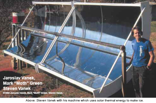 Also, a two-part article on Solar cooling, which concentrates on heat absorption with different colours, the strategic positioning of buildings and vegetation, practical roof overhangs and the like, to lower the temperature inside buildings in very hot locations. There are articles is on cooking with hydrogen, heating your house with hydrogen and using hydrogen with a barbecue. On the Home Power site there is information on how to use solar power to heat household water and you may find the Google video on how to make your own hot-water solar panel interesting and useful. This video is at and it shows very simple construction methods. It makes sense to reduce your essential costs by doing a few simple things which help. Cooling Using Heat. Most of our current refrigerators use electricity to drive a compressor to achieve cooling. Here is a patent from Albert Einstein (whom you may have heard of) and Leo Szilard which uses heat to power refrigeration instead of electricity. It is US Patent 1,781,541 titled “Refrigeration” and dated 11th November 1930.  Our invention relates to the art of refrigeration and particularly to an apparatus and method for producing refrigeration where the refrigerant evaporates in the presence an inert gas and more particularly, to the type disclosed in the Von Platen and Munters Patent No. 1,685,764 of 25th September 1928 and our British Patent No. 282,428. The objects and advantages of our invention will be apparent from the following description considered in conjunction with the accompanying drawing which shows more or less diagrammatically, a preferred embodiment of our invention. In the drawing, 1 is an evaporator which is normally placed inside the chamber which is to be cooled. A pipe 5 connects the upper part of evaporator 1 to the more intermediate portion of the condenser 6. Pipe 11 connects with the bottom of the evaporator 1 and extends into the condenser 6, at a level which is below the level of pipe 5. A cooling water jacket 12, surrounds the condenser and allows cooling water to flow through it. Pipe 27 connects the bottom of the condenser 6, to the lower part of a heat-exchanger jacket 28. The upper part of jacket 28, is connected to the lower part of generator 29 which is heated by any suitable method. Pipe 30 connects the upper part of generator 29 to a point near the bottom of evaporator 1 where it terminates in a distributor head 31. Pipe 30 runs inside pipe 5 so that there is a heat exchange between the fluids in those two pipes. Pipe 32 runs upwards from the lower part of generator 29 to connect with a container 33 which is positioned at a level which is above that of condenser 6. A source of heat 36, is applied to pipe 32 at a point above generator 29. Pipe 37 runs down from container 33, passing through the heat-exchanger jacket 28 and then on up to the top of condenser 6 where it terminates in a distributor head 35. Pipe 37 runs inside the cooling water jacket 12 so that the fluid passing through it will be cooled as it flows. A venting pipe 34 connects the upper part of container 33 with the upper part of condenser 6. The operation of the apparatus is as follows: A suitable refrigerant, for example, butane in liquid form, is held inside the evaporator 1. An inert gas, such as ammonia, is introduced into evaporator 1 through pipe 30 and it’s distributor head 31. The refrigerant evaporates in the evaporator in the presence of the inert gas due to the fact that the partial pressure of the refrigerant is reduced thereby and the resulting gaseous mixture passes through pipe 5 and into condenser 6. Here, the mixture comes into intimate contact with an absorption liquid, for example, water, which is fed into the condenser through pipe 37 and it’s distributor head 35. The ammonia gas is very soluble in water but the butane is quite insoluble, so the ammonia is absorbed into the water freeing the butane from the gaseous mixture. Thus, the butane assumes substantially the entire pressure inside the condenser, and that pressure is sufficiently high to cause its liquefaction at the temperature maintained by the cooling water. The specific gravity of liquid butane is less than that of the solution of ammonia in water and so stratification of the two liquids occurs with the liquid butane floating on top of the ammonia solution 26. The liquid butane passes from condenser 6, through pipe 11, and returns to evaporator 1, where it is again evaporated and the cycle repeated. Gravity causes the ammonia solution to flow from condenser 6 through pipe 27 and heat-exchanger jacket 28, into generator 29. Here, the application of heat causes the ammonia to be expelled from the solution in the form of a gas, which then passes through pipe 30 and distributor head 31, into evaporator 1, where it reduces the partial pressure of the butane, causing it to evaporate as already described. Water, containing very little ammonia in solution, passes from generator 29 through pipe 32 where it is further heated by the source of heat 36. This heating causes the formation of vapour in pipe 32 which lifts the liquid through this pipe and into container 33 and on from there under gravity through pipe 37 to condenser 6 and during its flow, this hot, low-concentration liquid is cooled by the heat-exchanger jacket 28. It is further cooled by the cooling water in jacket 12, and so reaches a condition where it can rapidly absorb ammonia in the condenser 6. Vapour entering container 33 through pipe 32, continues on it’s journey to the condenser 6 via the venting pipe 34. During the operation of this piece of equipment, the pressure existing in the various components is uniform with the exception of slight differences caused by columns of liquid needed to cause the fluids to flow. The pressure existing in generator 29 must be sufficiently greater than the pressure in the upper part of evaporator 1, in order to make vapour flow through distributor head 31. In other words, the pressure difference must be sufficient to overcome the liquid head marked h2. This excess pressure in the generator is balanced by the pressure created by the column of liquid marked h1 in the drawing. This means that h2 must be less than h1, otherwise there would be no flow. This patent of Einstein and Szilard seems to indicate that any source of heat such as a fire or a solar oven, should be able to produce cooling using a device which has no moving parts. It would probably be necessary to provide a trickle of water through the water cooling jacket, but apart from that, it looks like a device which could be used effectively by people who live “off the grid” and have little or no access to electricity. All in all, it is an interesting design. Solar panels. A very well-know method of producing electricity from what appears to be a renewable resource are solar panels. It hardly seems worth mentioning these as sales are so well promoted but it is possible that the problems with them are not understood. This is the most expensive way of producing electricity, and when there is a government scheme to cover one third or one half of the purchase price, it is quite likely that the chosen supplier has prices which are so high that it is cheaper to buy the panels direct from an outlet with competitive pricing rather than paying a much higher price with a subsidy. What is often not realised is that solar panels have a working life span and will need replacement at some later date. The life is quite good, typically ten to fifteen years, but the price is so high that replacement costs must be allowed for. Solar panels are not the only part of your electrical system which will need replacing. Generally speaking, solar panels are used to charge batteries which then power equipment, usually by using an "inverter" which changes a DC battery voltage to a mains voltage AC supply. The big snag is that the frequently used lead-acid batteries generally have a lifespan of about four years. They are expensive, heavy and as they contain lead, they are not easy to dispose of (legally). This is a major recurring cost and disposal problem. Another point which may not be realised is that the current which can be drawn from a battery without reducing its working life is very limited. The safe discharge rate is called the "C20" rate which just means that the allowable current is one which discharges the battery in a period of 20 hours. For example, if a new battery is rated as being a 100 Amp-hour ("100 AHr") battery, then the safe discharge rate is 100 amps divided by 20, which is 5 amps. At twelve volts, a current of five amps is a power output of sixty watts. A washing machine needs about 2,200 watts for at least some of the time, so to power it (and nothing else at the same time) would take 37 of those 100 AHr batteries. Could you conveniently house 37 large batteries? How much do you think it would cost to replace them every four years? Another point which is often missed is that batteries are by no means 100% efficient and that means that you have to put more current into them than you can draw out of them afterwards. After some time in use, you may only get between 50% and 80% of the power back from the battery bank. Please understand that I have nothing against solar panels and actually own three of them myself, but you need to be aware of the practical problems with using them and not imagine that buying them will give you free electricity for ever afterwards. The next factor to be considered is the fact that the power "rating" of a panel such as "120 watts" is not the amount of power which will be provided by the panel. It will provide that amount of power IF it is positioned exactly square-on to very strong sunlight in a region near the Equator. If the panel is not aimed exactly at the sun, then the panel output will be considerably lower. The sun moves around at a rate of fifteen degrees per hour, so your panel will only be aimed directly at the sun for about four minutes unless you have it mounted on a rotating platform and you push the platform round slowly to face the sun at all times. While that sounds complicated, it is actually not a difficult or expensive thing to arrange although most people don't bother to do that. Even though most solar panels operate on UV rather than visible light, any minor cloud cover drops the panel output quite noticeably. There is also the little detail that most solar panels only work in sunlight or with reduced output in very bright daylight. This means half the day does not contribute to electrical input and in winter, when the electrical need is greatest, the days are shortest, sunlight scarce and daylight quality very poor unless you live near the equator. The level of sunlight which you will receive drops off steadily the further you get from the equator as the light angle gets lower and lower. This also causes problems in winter with quite low obstacles casting a shadow on the panels and cutting the working time for the panel even further. The effect of all this is that you will need a far greater claimed panel wattage than your needs seem to require and I would suggest that you probably need between two and three times as many panels as the stated panel wattage would suggest that you need. Considering that chapter 10 shows how to run a generator on water, it would be cheaper to buy and replace a generator on a regular basis than to buy batteries and panels and having to replace them. A generator also runs at night and through the winter. However, if you are installing solar panels, please be aware that there are considerable differences between panels which have the same apparent rating. A key factor is the voltage produced by the cell under normal working conditions. This makes the difference between a good charging rate under poor conditions and a near-zero charging rate at those times. The good panels have a greater number of cells and the higher voltage produced can make a major difference, so check out the technical specification document on each panel you want to consider and pay attention to the voltage figures and not just the (maximum possible) "wattage" quoted by the manufacturer or sales person. The panels which I picked are made by Kyocera but do your own checking as designs change from year to year. At the present time, solar panels are only about 17% efficient which means that 83% of the power reaching them does not go to make electricity. Solar panels change size during the day and so need to be mounted in such a way that allows for this expansion and contraction during the day and night. As you don't want to over-charge a battery, it is generally considered essential to use a control circuit to prevent this happening. In real life, when you use the electricity generated on a daily basis, there is little or no chance of over-charging, but you can decide this for yourself. Assessing solar panels generally from the standpoint of knowing what the snags are, unless you live in a very good location on the planet and have a good deal of spare money to spend, then they are not a great solution, but this is something which you also need to decide for yourself. Patrick Kelly engpjk@yahoo.co.uk http://www.free-energy-info.co.uk/ |