| This chapter covers a number of
devices which either are unlikely to work, or which have too little
practical information available to assist replication attempts. This
selection, is of course, a matter of opinion. Paul Baumann’s “Thestatika” Machine. This device is a perfect example of a free-energy device as it powers itself and provides kilowatts of excess mains electrical power. It is in this section, not because its operation is "doubtful" in any way, but because the design has never been fully disclosed. It was developed by the late Paul Baumann who was part of a Swiss commune which is not willing to explain its operation. This “Thestatika” or “Testatika” machine works beautifully and has a very high quality of workmanship. It has two electrostatic discs which are initially rotated by hand and which then continue to rotate driven by the power produced by the device. There are various ideas as to how the device operates. The Swiss commune no longer shows this device to people as they have the theory that "mankind" is not ready to have, or use free-energy. They have always refused to show what is inside the large cylinders mounted on each side of the device. D. A. Kelly's 1991 document provides some very perceptive comments on this device. He says: The "Swiss M-L Converter" is a fully symmetrical, influence-type energy converter which is essentially based on the Wimshurst electrostatic generator with its twin counter-rotating discs where metallic foil sectors generate and carry small charges of electricity to be stored in matched capacitors. In Wimshurst units, diagonal neutralising brushes on each opposite disc distribute the correct charges to the sectors as they revolve, but in the M-L converter this is carried out by a crystal diode which has a higher efficiency. Two brushes collect the accumulating charges and conduct them to the storage capacitor located at the top of this device. The device has two horseshoe magnets with matched coils and a hollow cylindrical magnet as part of the diode function, and two Leyden jars which apparently serve as the final capacitor function for the converter. The use of top grade components such as gold-plated contacts, control electrodes and dual capacitor stages, insure much higher conversion efficiencies than those available with a Wimshurst machine. The details of the operating prototype are: 1. Efficiency: The unit is started by hand and no other input power is required. 2. Constant power output: 300 volts at 10 amps = 3 kilowatts. 3. Dimensions: 43.31" (1100 mm) wide, 23.62" (600 mm) tall, 17.72" (450 mm) deep. 4. Weight: 44 lbs (20 Kg). 5. Operating speed: 60 rpm. (low speed - one revolution per second). The twin discs are made of acrylic (plastic) and the metallic segments are steel, which causes the Searle Effect with electromagnetic conversion made at the rim of the discs through passive electromagnets. This is an ideal converter since both high voltage AC and moderate AC amperage can be generated simultaneously via two separate electrical circuits from the discs. The conventional conductive brushes pick off the high voltage AC while the rim electromagnet coils produce useful amperage. When permanent horseshoe magnets with coils are used, then the output power is enhanced to a considerable extent as shown by the above output specifications. The self-propulsion after hand-starting the discs is achieved through the adoption of the Poggendorff principle (a German scientist of the 1870s) in which slanted conductive brushes produce self-rotation in electrostatic motors (not generators). The special crystal diode module probably provides the dual functions of frequency regulation and capacitance amplifier - to the two Leyden jars - as part of the electrical resonance circuit, since it is connected with the horseshoe magnet coils. This device is comprised of three separate electrical circuits: 1. The high voltage AC output from the twin electrostatic discs. 2. A moderate AC amperage circuit provided by the dual horseshoe magnet coils (Searle Effect) as the plus and minus discs pass by them. (Pulsed DC output at 50 Hz). 3. A resonant circuit in which the horseshoe magnet coils are connected to the diode capacitor so that frequency regulation is assured. The diode capacitor is then connected to the Leyden jar, transmitter unit. The major physical principles involved in this outstanding composite unit are: 1. Electrostatic conversion using twin discs for positive output from one and negative output from the other. 2. The evidence of the Searle Effect from the use of multiple, identical steel segments inducing and EMF in electromagnets at the rim of the discs. 3. The Ecklin principle is also in evidence, since the steel segments pass by permanent horseshoe magnets, as in Ecklin's S.A.G. units. 4. The Poggendorff self-rotating electrostatic motor principle as described above. 5. The crystal capacitance function of the crystal diode module. The full operation of this unique component with its hollow cylindrical permanent magnet, is a composite component with the dual functions of distributing the correct charges to the sectors, and maintaining the output frequency at the desired value.  The M-L Converter is completely symmetrical with two acrylic discs, a light metal lattice, insulated copper wires, a secret crystal-diode rectifier, and gold-plated electrical connections. These machines have been developed over a period of twenty years. In electrostatic generators, the air molecules between the two acrylic discs which counter-rotate closely side by side, become electrically activated by friction. This causes the discs to be continually charged until a flashover equalises the charge on them. To limit the voltage to the desired amount, the positively charged particles on one of the discs and the negatively charged particles on the other disc are each extracted by means of separately adjustable lattice-electrodes, and are fed into a Leyden jar which collects the energy. The speed of the discs which have 50 lattice electrodes, is 60 rpm which produces a 50 Hz pulsed DC output. This speed is synchronised by magnetic impulses. The unit is hand started by revolving the two discs in opposite directions until the Converter is charged up enough to synchronise itself and continues to rotate smoothly and noiselessly without any external source of input power. A centrally mounted disc of about 4" (100 mm) in diameter glimmers with all the colours of the rainbow. After a few seconds the Leyden jars are ready for operation and 300 volts DC with a current of 10 amps can be drawn from the device for any desired length of time. On many occasions, demonstrations have been made of the power available from the device. Heating elements, lights and hand power tools can be run from the device. This suggested explanation of the M-L Converter contains a number of very interesting points. It has seemed mysterious that the electrostatic discs continued to rotate on their own without any visible motor driving them. Mr Kelly, who has seen the device and its operation, suggests that there are sloping brushes pressing against the front and rear faces of the twin electrostatic discs and that these are supplied with electrical current from the horseshoe magnet coils and that acts as a motor which drives the discs onwards once they have been started. He also suggests that the fifty steel segments per second which pass between the poles of the horseshoe magnets cause a rapidly fluctuating magnetic field through the magnet coils, which makes them operate as an Ecklin electrical generator, as described elsewhere in this eBook. Mr D. A. Kelly also suggests that the two cylinders seen on the M-L Converter, are Leyden jar capacitors and that they work together as described by Sir Oliver Lodge (whose book is on this website). This is a very interesting suggestion, but it does not explain why the people in the Swiss commune refuse point-blank to let anyone see what is inside those cylinders. There is a video produced by Don Kelly (presumably, a different person) which puts forward another theory of operation. He suggests that each of the cylinders contains a bi-filar coil on a barium ferrite magnet:  However, he describes the barium ferrite magnet as being the same type as used in radio receivers, and they are standard "ferrite rods" which are not permanent magnets as far as I am aware. Don suggests that the output from the high-voltage electrostatic discs gets fed directly to these coils and then on via a series connection to the coils around the horseshoe magnets. He envisages the bi-filar coil amplifying the current and the electrostatic discs being rotated by a standard low-voltage DC motor. Another possibility is that the jars also contain a spark gap and surrounding copper pick-up shells and as the machine operates silently, the jars have a vacuum inside them. That would provide silent operation and explain why the people in the commune could not open them for inspection. It seems very clear that we just don't know exactly how this device operates. One very interesting fact which has been reported by the Swiss group is that if a series of copper, aluminium and Perspex sheets are placed in a magnetic field, they generate a high voltage. This is worth investigating. It is not clear if the magnetic field should be constant or oscillating. The sequence of plates is said to be: cpacpacpacpa (“c” being copper, “p” being ‘Perspex’ (acrylic or ‘Plexiglas’) and “a” being aluminium). The following set-up might be worth investigating:  If you wish to understand the operation of electrostatic discs, then the McGraw-Hill book “Homemade Lightning” by R.A. Ford (ISBN 0-07-021528-6) gives full details of Wimshurst machines and plans for constructing your own, improved version. Ready-built Wimshurst machines are available from this web site. The Homopolar or “N-Machine”. This device was the brainchild of Michael Faraday and has an intriguing method of operation and a remarkably large output.  The principle of operation is incredibly simple:  If a copper disc is rotated in a magnetic field, then power is developed between the shaft and the outer edge (or any intermediate position). It was then found that the device will still operate even if the magnet is attached to the copper disc and rotates with it - not something which is intuitively obvious. The power output is tremendous with the capability of extracting 1000 Amps but at a low voltage of less than 1 Volt. The power take-off can be from one face of the disc near the shaft rather than having to have a copper shaft integral with the copper disc. This looks like a very viable starting point to develop a device which can run itself and provide useful additional output, since a motor to rotate the disc will not require anything remotely like 1000A to drive it. The snag is, it is very difficult to provide reliable sliding contacts capable of handling large currents for extended periods of time. The second picture above shows the disc with its outer edge immersed in a bath of mercury. This is sufficient for a brief demonstration at low power but not realistic for a serious working device. It might just be possible to get a reasonable working device by accepting that the current output is not going to be anything like 1000A. Long-life brushes could be made from solid copper bar and spring-loaded against the copper disc in matching pairs so that the brush thrusts oppose each other and so do not generate a sideways load. These could be made in multiple sets for each disc, say four or eight per disc, so that the effective electrical resistance between the brushes and the disc is reduced and the possible current draw increased. Similar multiple brushes could be applied to the central shaft cylinder. Multiple discs could then be mounted on a non-conducting, non-magnetic shaft and their brushes wired in series as shown, to raise the output voltage:  The “Romag” and “Mini-Romag” Generators. These generators have been displayed on the internet for some considerable time now. They can be found on the Jean-Louis Naudin website.  The Mini Romag generator from Magnetic Energy uses the principle of moving magnetic flow named "the magnetic current" for generating electrical power. According to Magnetic Energy this generator is able to produce 3.5 volts, 7A DC (24 Watts) of free electricity plus sufficient power to sustain itself. This generator needs to be started by using an external motor to rotate it at 2,100 rpm for some 42 seconds. After this, the energy flow is established in the Romag generator and the external motor can be removed and the free electrical energy output can be used.  The starting procedure generates magnetic energy within the six coils of copper wire, the copper tube supporting these coils and the copper coated steel wires wrapped around the magnets. This charging is accomplished while the six coil connection wires, (shown as 22 in the above drawing), are making contact and setting up their alternating magnetic poles. After the 42 second start-up time one of these coil connection wires is opened by switch (24 above) leaving the working load in its place. The load (23 above) can draw 7 amps. As current is drawn from the six coils, it sets up magnetic poles which react with the rotor magnets maintaining the rotation. The main shaft is rotated by the 12 permanent magnets as they attract and build a release field. Then the driver unit (hand crank or motor) is disconnected allowing the unit to continue rotating with the load being the activating driving force.  Construction: If you decide to attempt to build one of these units we suggest using the stated materials:
Cold Fusion. Cold fusion was initially accepted with great excitement. It then appeared to be discredited. However, at the present time, there are been some two hundred labs. which have confirmed the findings and so there is no doubt as to the reality of the system. In essence, it is said that nuclear fusion can take place at room temperature, under certain conditions. However, developers are struggling to develop a serious working device and although the process has now been confirmed without a doubt, a practical free-energy device based on this method appears to be some time away yet. There are several web sites which follow the progress in this field, including Cold Fusion Times where considerable detail is available. Moller’s Atomic Hydrogen Generator. One already successful experiment can be found here where the highly resourceful researcher JL Naudin shows many successful tests on a system which can be found here. Please check out these very well presented sites. This system should not be called the “Moller” system as it was originated by William Lyne and published in his book “Occult Ether Systems” in 1997. William Lyne states that in 1999, Nikolas Moller bought a copy of his book and subsequently claimed that he (Moller) had invented the Atomic Hydrogen Generator, quoting directly from Lyne’s book. This system should be called the “Lyne Atomic Hydrogen Generator”. This system involves repeatedly converting a completely contained body of hydrogen gas from its diatomic state (H2 where two hydrogen atoms are bonded together to form a stable molecule), to its monatomic state H-H (where two hydrogen atoms remain as separate atoms, not closely bonded together) and back again. No hydrogen is consumed. No additional gas is required. The gas is just converted from one state to the other repeatedly. The problem for conventional science is that the output power measured in tests is typically 15 times greater than the input power in carefully measured tests run for periods of more than half an hour. Clearly, additional power is coming from somewhere - possibly the Zero-Point Energy field, possibly from the conversion of a minute amount of the gas from matter into energy (which would make this a practical, room temperature, nuclear reactor). In spite of these results, there appears to be little interest in this system. Just to give you an idea of the type of content of the web site:  Results of one test:  Muammer Yaldiz’s “Ocean Star” Electrical Generator. This is a purely mechanical device which is self-powered and which can provide electric current to drive other equipment. Designed and built in Turkey, it was demonstrated in Dortmund on 17th October 2005. Details of this system can be seen here, including video footage of the demonstration with commentary in both English and German. The demonstration was conducted by J. L. Duarte who ran an independent test and produced a report dated 17th July 2005 on behalf of the Department of Electrical Engineering, Electromechanics and Power Electronics of the Eindhoven Technische Universiteit. Muammer has obtained Patent Application WO2004091083 for his design. The demonstration was of his portable unit which outputs some 12 volts DC:  During the demonstration was used to light a car light bulb very brightly:  Muammer has also produced a larger version capable of powering a house: 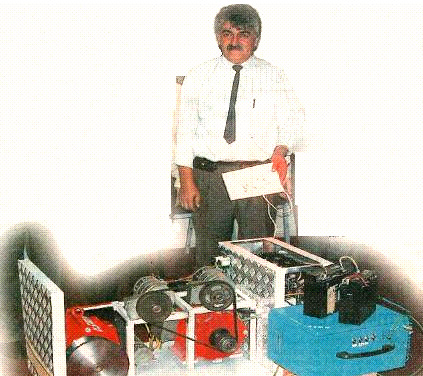 The demonstration unit was started using a 16 AHr battery for a few seconds. Once the unit reaches its running speed, it becomes self-powered and capable of delivering substantial electrical power and the starting battery is then disconnected. In theory, no mechanical system can produce 100% efficiency, let alone more than 100%. However, it appears that automotive and marine alternators may well operate well in excess of 100% efficiency and so it would not be impossible for Muammer’s device to actually work. The report by Dr. J. L. Duarte on the smaller unit provides the following information: This technical note aims at describing a test which I personally conducted in Izmir, Turkey on 17th July 2005. The purpose of the experiment was to check the energy balance with respect to input and output of an apparatus which was the embodiment of the invention described in the international patent WO 2004/091083 A1 (shown below). The apparatus was confined inside a metallic box sized 550 x 380 x 270 mm, weighing some 20 Kg, and I was allowed to inspect everything outside this box. However, in order to protect the core ideas of the invention, I was not supposed to check all the details of the internal parts. According to the inventor, the apparatus is predominantly a mechanical system, without any kind of energy storage inside the box (such as batteries, accumulators, flywheels, combustion motors, chemical or radioactive reactions). I believe the intentions of the inventor to be in good faith. The experimental set-up was quite simple, as shown schematically in Fig.1. It consisted of placing the box with unknown contents, from which DC voltages and currents were expected to be generated, on a table in the middle of the room. A cable with two terminal contacts was run from the box and instruments were placed between the box and the load, which was a standard DC/AC inverter driving an incandescent lamp. The output power from the box was measured before the load connection as shown here:  The circuit connection method used is shown here:  After a short start procedure, the metallic box and the load were both fully isolated from the environment, ensuring that there was no physical contact or connection to external power sources such as the public electric mains supply, at any time during the whole duration of the measurements. As the start-up energy input to the apparatus was quite modest, the main issue was then to measure the delivered energy output. I had prepared the power measurements with care, by using reliable instruments which I personally brought with me from my own University laboratory. In order to measure the DC voltage directly out of the positive and negative terminals, I used two different voltmeters connected in parallel. One voltmeter was an analogue type, constructed with permanent magnets and wires, while the other was a digital voltmeter. To measure the DC current I used two ammeters in series, one analogue and one digital. If electromagnetic waves should interfere with the measurements, then they would disturb one or other instrument, but not all four pieces at the same time and in the same way. Before starting the test, no audible sound was being produced by the apparatus. The measured voltage and current at the terminals were zero. So, as far as I could observe, the apparatus was completely at rest. The start-up procedure consisted of connecting a small 12V DC lead-acid battery to two contact points inside the box for a few seconds. I checked the time using my own watch and it was more than 5 seconds but less than 10 seconds. I consider it reasonable to consider the time to have been 8 seconds. After that time, no energy input was connected to the box by means of cables. Immediately after the start-up procedure, I could hear noise such as would be produced by parts rotating inside the box. The inventor said that some ten minutes should be allowed to elapse before the load was connected. During that time, both of the voltmeters showed the output voltage dropping slowly from 12.9 volts to 12.5 volts. The two voltmeters matched accurately. In the following hours, I observed and recorded by hand, the voltage and current values displayed by the instruments. The displayed values were quite stable, so I initially decided to note them at 15 minute intervals, but later on at 30 minute intervals. From time to time, using my hands, I attempted to find a temperature gradient inside the box, but I could not detect any variation or increase in the temperature compared to the room temperature. After five hours, I took the decision to stop the measurements. The results are shown in the following table:  As far as I am concerned, the above table of results kills the proposed system stone dead. The voltage readings are absolutely typical of an inverter powered by a lead-acid battery. I have tested many batteries in exactly the same way and the table looks 100% familiar. If the box contained a genuine self-powered generator, then I would expect the output voltage to remain constant under the constant current drain. In my opinion, it was wholly irresponsible to have stopped the test after just five hours with the output voltage falling steadily. If the output voltage had been rock steady at 12.5 volts for the whole five hours, then that would not have been quite so bad but with it going down 12.3, 12.2, 12.1, 12.0 in the last four 30-minute intervals, and with a lead-acid battery voltage of 11.5 for a fully discharged battery, it was wholly unrealistic to stop the test. A further ten hours of testing should have been undertaken. For that reason, the OceanStar information is placed here, among the “Unlikely to Result in a Workable Device” section. However, on the basis that I am not infallible and it is possible that this system may actually work as described, here is the information from the Patent Application WO2004091083 although the quality of reproduction and the clarity of the wording is not particularly good: ACCUMULATOR THAT PROVIDES THE INITIAL MOTION FOR THE SYSTEM ABSTRACT This is a portable system that generates electrical power via an accumulator that provides the initial motion for the system. Two batteries are used in this system and the system is kept working via the initial motion provided by these batteries. There is no need for another transformer. This device works using its own mechanism and there is no need for additional devices. In this way, a continuous electrical power generation is possible. This device can work without connecting it to a network so it is possible to use it at places where electricity does not exist. Moreover, when connected to the entry of a building, the need for a network is avoided. This system generates electrical power independent of a network. DESCRIPTION A system which generates electrical power via an accumulator that provides the initial motion for the system This is a portable system that generates electrical power via an accumulator that provides the initial motion for the system. Already existing systems can generate electric power of whose duration depends on the lifetime of the battery. In these systems, the battery has to be reloaded in order to restart the system. 12V electrical power provided by the batteries used in cars is increased to 220 V via transformers. Two accumulators are used in our invention. The system works on a continuous basis after the initial start up via these accumulators. There is no need for another transformer. Our system, which generates electrical power, does not need any other devices and it keeps on generating energy via its own mechanism. Also, the system works without connecting it to a network. Thus, it can be used at any place where no electricity exists. Nevertheless, when this system is connected to the entry of the buildings, there is no need for an additional network. The system can produce electrical power independent of a network. DESCRIPTION OF THE DRAWINGS Below are the explanations of the figures that provide a better understanding about this invention.  Numbers used on the schematic:
 DESCRIPTION This invention is a system that starts working via the motion of alternator. There exist two accumulators(1), and the first motion provided by the accumulator is carried to the regulator. Contactor (6) keeps the starter dynamo working by disconnecting the accumulator (1) once the regulator (2) is put in. The voltage coming from the accumulator (1) passes through the regulator and the start dynamo (3/1) starts working and thus the feedback alternators via the gears (4/1-2-5/1-23-3). Feedback dynamo start sending pure DC current to regulator via shunt (12), capacitor (14) and diode (13). It connects all the currents that reaches to the regulator in 4 seconds and sends to the contactor (6). Accumulator (1) is put out by this current that reaches to the regulator. This current is transformed to the started dynamo (3/1). There becomes a. transformation within the system. In case of electricity shortage, it keeps on working by using the current generated by the commitatris (7/1). Via the starter dynamo(3/1), DC is generated in the alternators which are connected to the gears and this current is transformed to the commitatris (7/1 and 7/2) and DC voltage is generated at commitatris (7/1 and 7/2). Second System: 3x24 DC voltage is transformed to the second starter dynamo (22). Once the start dynamo works (22), a feedback dynamo (23) having a pulley system and a feedback dynamo (24) generating alternating current starts working. The feedback dynamo (23) starts feeding back; the feedback dynamo (24) which generates alternating current is independently generating 6 KV, 18 Amp, 50Hz current. Moreover, first system produces 24 DC and 580 DC current on its own. The bigger the gears are, the more the generated current is. This system, which is the subject of our invention, can be used at any place. You can use it at places where there exist no electricity, or at places such as villages, cities, buildings, greenhouses where there is no network. Moreover, network is no longer a must. Instead of a network, you can use our system. There is no need for gasoline when this system is used in vehicles. Jesse McQueen. There is a US patent which was granted to Jesse McQueen in 2006. This system looks too good to be true and, on the surface, appears impossible, even taking into account that it has been said that ordinary vehicle alternators have a Coefficient Of Performance over one (i.e. output energy is greater than the energy that the user has to put into the device to make it operate). I am not aware of anybody who has tried this system, so I have no evidence that it doesn’t work - just a lack of belief in a system of this type being able to operate as described. As against that, the US Patent office has granted this patent and they have a reputation of being highly opposed to admitting that there is any such thing as a “perpetual motion machine”, which this system clearly is. So, I leave it up to you to make up your own mind, and test the system if you wish, which should be easy to do as it involves no real construction, but instead, uses off-the-shelf manufactured products which are readily available and not particularly expensive. Here is the patent: INTERNAL ENERGY-GENERATING POWER SOURCE ABSTRACT An external power source such as a battery is used to initially supply power to start an alternator and generator. Once the system has started it is not necessary for the battery to supply power to the system. The battery can then be disconnected. The alternator and electric motor work in combination to generator electrical power. The alternator supplies this electrical power to the two inverters. One inverter outputs part of it’s power to the lamp, and part back to the electric motor/generator. This power is used to power the electric motor. The second inverter supplies power to the specific load devices which are connected to the system. US Patent References: 5033565 July 1991 Abukawa et al. 5036267 July 1991 Markunas 5785136 July 1998 Falkenmayer et al. BACKGROUND OF THE INVENTION Electrical energy occurs naturally, but seldom in forms that can be used. For example, although the energy dissipated as lightning exceeds the world's demand for electricity by a large factor, lightning has not been put to practical use because of its unpredictability and other problems. Generally, practical electric-power-generating systems convert the mechanical energy of moving parts into electrical energy. While systems that operate without a mechanical step do exist, they are at present either excessively inefficient or expensive because of a dependence on elaborate technology. While some electric plants derive mechanical energy from moving water (hydroelectric power), the vast majority derives it from heat engines in which the working substance is steam. Roughly 89% of power in the United States is generated this way. The steam is generated with heat from combustion of fossil fuels or from nuclear fission. In electricity, a machine is used to change mechanical energy into electrical energy. It operates on the principle of electromagnetic induction. When a conductor passes through a magnetic field, a voltage is induced across the ends of the conductor. The generator is simply a mechanical arrangement for moving the conductor and leading the current produced by the voltage to an external circuit, where it actuates devices which require electricity. In the simplest form of generator, the conductor is an open coil of wire rotating between the poles of a permanent magnet. During a single rotation, one side of the coil passes through the magnetic field first in one direction and then in the other, so that the induced current is alternating current (AC), moving first in one direction, then in the other. Each end of the coil is attached to a separate metal slip ring that rotates with the coil. Brushes that rest on the slip rings are attached to the external circuit. Thus the current flows from the coil to the slip rings, then through the brushes to the external circuit. In order to obtain direct current (DC), i.e., current that flows in only one direction, a commutator is used in place of slip rings. A commutator is a single slip ring split into left and right halves that are insulated from each other and are attached to opposite ends of the coil. It allows current to leave the generator through the brushes in only one direction. This current pulsates, going from no flow to maximum flow and back again to no flow. A practical DC generator, with many coils and with many segments in the commutator, gives a steadier current. There are also several magnets in a practical generator. In any generator, the whole assembly carrying the coils is called the armature, or rotor, while the stationary parts constitute the stator. Except in the case of the magneto, which uses permanent magnets, AC and DC generators use electromagnets. Field current for the electromagnets is most often DC from an external source. The term dynamo is often used for the DC generator; the generator in automotive applications is usually a dynamo. An AC generator is called an alternator. To ease various construction problems, alternators have a stationary armature and rotating electromagnets. Most alternators produce a polyphase AC, a complex type of current that provides a smoother power flow than does simple AC. By far the greatest amount of electricity for industrial and civilian use comes from large AC generators driven by steam turbines. SUMMARY OF THE INVENTION It is an objective of the present invention to provide an energy source that generates more energy than the energy source requires in order to operate. It is a second objective of the present invention to provide a system that uses the excess energy produced by the energy source to power other various devices. It is a third objective of the present invention to provide an energy source for supplying power to various devices without the reliance on an external energy source for supplying power to the energy source of the present invention. The present invention provides an energy source that is capable of producing more energy than it requires to operate. The excess energy is used to power devices. A feedback loop approach is used to channel a portion of the energy produce by the generator back to the generators power input port. This feedback loop approach enables the generator to use its own generated energy to operate. The additional energy generated by the generator is used to power other devices that can be connected to the generator. In the method of the invention an external power source such as a battery is used to initially supply power to start an alternator and generator. Once the system has started it is not necessary for the battery to supply power to the system. The battery can then be disconnected. The alternator and electric motor work in combination to generate electrical power. The alternator supplies this electrical power to the two inverters. One inverter outputs part of its power to the lamp load device and part back to the electric motor/generator. This power is used to power the electric motor. The second inverter supplies power to the specific load devices that are connected to the system. DESCRIPTION OF THE DRAWINGS Fig.1 is a configuration of an implementation of the internal power generating system of the present invention. Fig.2 is a configuration of an alternate embodiment of the internal power generating system of the present invention. DESCRIPTION OF THE INVENTION  This invention is an electric power-generating device that produces several times more power than it takes to operate this system. This invention comprises a first power source that is connected to a second power source. Referring to Fig.1, the system of the present invention comprises a battery source 10 (12 volt DC) that connects to an electrical alternator 20. The battery supplies the initial power to the system to initiate/start the operation of the alternator. The present invention can implement other power sources in addition to the illustrated battery to supply the initial power to the system. In the initial model of the present invention incorporated an alternator from a 1997 Isuzu Trooper. The invention incorporates an electric motor 30 (148 watt AC). The electric motor connects to an inverter 40 (400 watt AC). The system also comprises a second inverter 50. The battery 10 also connects to both inverters 40 and 50. Each inverter has two outputs. For the first inverter 40, one output feeds into the electric motor 30 to provide to the motor and alternator combination. The other output feeds into a lamp device 60. The lamp device is a 60-watt AC lamp. This lamp device alters the current travelling from the inverter 40 such that the current feeding into the electric motor 30 is not purely inductive. Although, Fig.1 shows a lamp device, other loads can be used to accomplish this same a task. The inverter 40 has an input from which the inverter receives power from the alternator 20. The second inverter 50 also has an input that also receives power from the alternator. In operation, initially, the battery 10 is used to supply power to start the alternator 20 and generator 30. Once the system has started, it is not necessary for the battery to supply power to the system. The battery can then be disconnected. Once started, the alternator 20 and electric motor 30 work in combination to generate electrical power. The alternator supplies this electrical power to the two inverters 40 and 50. Inverter 40 outputs part of this power to the lamp 60 and part to the electric motor 30. This power is used to power the electric motor. The second inverter 50 supplies power to the specific load devices which are connected to the system. These load devices can be any devices which operate by using electrical power. The key aspect of the present invention is the loop between the alternator 20, electric motor 30 and the first inverter 40. A portion of the power generated by the electric motor is recycled and is used to power the electric motor. In this way the system produces the power internally that is used to power the system. This concept makes this system a self-power generating system.  Fig.2 shows an alternative embodiment of the power generating system of the present invention. This embodiment incorporates a gear box 70, a car starter 72, and a head brush generator 74, and buck booster 76. Initially, the car starter 72 works with the battery to supply power to the generator. This process is similar to the process of starting a car. The gearshift 70 increases the rpm of the generator. The Buck Booster 76 serves as the output to supply power to the various loads. This configuration also incorporates a DC converter 78. The Nitro Cell. This document was originally produced at the request of an Australian man who said that the cell worked well for him but that he was afraid to publish the details himself. This document was prepared, approved by him and published. It proved very popular and an enthusiast group was set up to build and test this “Nitro Cell”. The results of this building and testing have been most unsatisfactory. As far as I am aware, not a single cell proved successful in powering an engine. I therefore, withdrew the document, since even though I believe it to be capable of working, the fact that many people failed to get it working indicates to me that this document should not be in a “practical” guide. I have been assured by two separate independent sources, both of which I rate as being reliable sources, that there are “hundreds” of these cells working in Australia and the USA. I have repeatedly been asked for copies of this document, so I am publishing it again, but requesting you, the reader, to be aware that should you make one of these devices, that it is unlikely that you will get it operational. Having said that, I understand that it may work very well as a booster. Simple arithmetic applied to the claimed performance of this device, shows that much of the claimed mileage has to have been covered without using any fuel at all. While this sounds impossible, in actual fact it is not, but that sort of operation comes from the Joe Cell which is notoriously difficult to get operational, requiring at least a week of fiddling around to get the metalwork of the vehicle aligned with the energy field used to provide the motive power. Also, each person acts as a “dipole” which produces an energy field around that person. Most people have a polarity which opposes the Joe Cell energy, and they will never get a Joe Cell to operate as they can disrupt such a cell from several paces away from it. The D10.pdf document which describes the Joe Cell includes information on how to reverse your own personal polarity, to stop blocking the cell performance. This definitely sounds unbelievable, but as it happens to be the way that things actually are, there is little point in pretending otherwise. Personally, I never recommend anybody to build a Joe Cell for powering a vehicle, as the likelihood of success is so low. However, having said that, a friend of mine in the USA has his Joe Cell connected to his truck in “shandy” mode where the carburettor is left connected to it’s normal fossil fuel supply. The vehicle is perfectly capable of drawing in fossil fuel to run the engine, but it just doesn’t. His fuel consumption is literally zero and he is driving around powered solely by the energy channelled into the engine by the Joe Cell. This is most unusual, and I do not recommend you spending time and money on building such a cell. I mention these cells so that you can know all about them, but I would leave it at that. Here is the original “D18” document, which is followed by important update information: A Different Fuel In the early days of heavier than air flight, observations were made and based on those observations, practical operating rules were deduced. After a time, those rules became called the “laws” of aerodynamics. These “laws” were applied to the design, building and use of aircraft and they were, and are, very useful. One day it was observed that if you apply those laws of aerodynamics to bumble bees, then according to those laws, it was not possible for a bee to fly since there was just not enough lift generated to get the bee off the ground. But simple observation shows that bees do in fact fly and they can rise off the ground when they choose to do so. Does that mean that the “laws” of aerodynamics are no good? Of course not, as they have been shown to be of great practical use when dealing with aircraft. What it did show was that the existing laws did not cover every instance, so research was done and the laws of aerodynamics were extended to include the equations for lift generated by turbulent flow. These show how a bee can develop enough lift to get off the ground. Do bees care about this? No, not at all, they just go on flying as before. What has changed is that the understanding of scientists and engineers has been extended to better fit the world around us. Today, people who are trained in science and engineering are fed the idea that internal combustion engines need to consume a fossil fuel in order to operate. That is not strictly true and at the present time, engines using hydrogen gas as a fuel are becoming commonplace. Unfortunately, most of the hydrogen produced for this use, comes from fossil fuels, so these vehicles are still running on a fossil fuel, though only indirectly. The “laws” of engineering say that it is not possible for an internal combustion engine to run without consuming some sort of fuel. Unfortunately, Josef Papp has demonstrated an internal combustion engine which has had it’s intake and exhaust systems blanked off. Filled with a mixture of inert gasses, during one demonstration, that Volvo engine ran for half an hour, producing a measured 300 horsepower, and apparently consuming no fuel at all. Josef received US patent 3,680,432 for his engine and you can see a video of one of his engines running. Robert Britt designed a similar sealed motor filled with a mixture of inert gasses, and he received US patent 3,977,191 for it. Does this mean that the current laws of engineering are of no use? Certainly not, they are vital for everyday life today. What it does mean, however, is that the present laws need to be extended to include the effects shown by these engines. Another thing widely accepted today is that an internal combustion engine can’t use water as a fuel. Well.... let’s leave that to one side for the moment and look at it from a slightly different angle. Engines can definitely run using air and hydrogen as the fuel, there is no argument about that as there are many vehicle around which do just that. If you pass a current through water, the water breaks up into hydrogen gas and oxygen gas, this mixture is called “hydroxy” gas and that can most definitely be used, along with air, as the fuel for an internal combustion engine. But... this gas came from water, so is it really correct to say that water cannot be used as the fuel for an internal combustion engine? Ah, says somebody with relief, that is not the case, because you are using water and electricity to get the fuel for the engine. But... the average vehicle powered by an internal combustion engine, has an alternator which produces electricity when the engine is running, so there is a source of electricity to do the electrolysis of the water and produce the gas to run the engine. But the laws of engineering say that you can’t get enough electricity from the alternator to produce enough gas to run the engine. Engineers will point to the work of Faraday who examined the process of electrolysis in great detail and produced the “laws” of electrolysis. These laws show that you can’t get enough electrical power from an engine to make enough gas to run the engine. Unfortunately, there have been several people who have done just that, so we have reached the point in time when these “laws” need to be extended to cover cases not covered by the work of Faraday. People have got from 300% to 1,200% of the gas output which Faraday considered to be the maximum possible. Several people have run vehicles on hydroxy gas produced by electrolysis of water using electricity generated by the vehicle’s alternator. This shows clearly that it can be done, and as a consequence, the “laws” need to be extended to include the newer techniques. Leaving that aside for the moment, there have been at least two people who have managed to power an engine with water as the only fuel, and without using electrolysis. In this instance, a fine spray of water droplets inside the cylinder is acted on by the spark, and a secondary electrical supply from an inverter boosts the spark, forming a plasma discharge. The result is a power stroke nearly as powerful as using a fossil fuel. For the moment, let us also ignore that style of operation. This document describes another system which uses water and air as the primary fuels, but again, does not use electrolysis to generate hydroxy gas for use in the engine. Instead, the objective is to create a continuous supply of Nitrogen Hydroxide (NHO2) for use as the fuel. This system has worked well for a number of people but there has been considerable intimidation and most of these people are very reluctant to pass the information on. This document is an attempt to present those details clearly enough to allow the system to be replicated by anyone who wishes to do so. So, how exactly is this fuel generated? The production method is described as the fuel gas being synthesised by a mixture of stream water and rock salt (the mineral "halite") in the presence of air, being acted on by engine “vacuum”, electrolysis and a strong magnetic field. This fuel is said to be more powerful than hydrogen and is a much more viable fuel source as less of it is needed to run an internal combustion engine. This system may be used with any internal combustion engine, whether used in a vehicle or stationary when powering an electrical generator or other equipment. The additional equipment consists of one, or more, horizontal cylinders mounted near the engine. A single, horizontally mounted, cylinder can generate sufficient gas to power an internal combustion engine up to two litres in capacity. Larger engines will need two cylinders to generate enough gas for them to operate. It must be stressed that this is not a hydroxy gas electrolysis cell. One test vehicle has been run on this system for a distance of 3,000 miles (4,800 kilometers) and the liquid fuel used was only 2 litres of water and 2 gallons of petrol. Two litres of water converted to hydroxy gas will definitely not power a vehicle engine for anything like 3,000 miles, so let me stress again that the fuel being generated in this cell is Nitrogen Hydroxide (NHO2). It should be noted that if the cell described here is used as a booster for the original fossil fuel, then it will not be necessary to upgrade the engine by fitting stainless steel valves, piston rings, exhaust system, etc. The person using this system which is shown in the following photograph, has opted for an exceptionally long generation tube attached to his stationary generator: 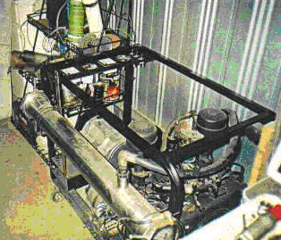 The versions of this cell design shown in the previous photograph and the following photograph, are early models which were in use before it was discovered that there was a considerable enhancement in gas production if a coil is wrapped around the cylinder. For vehicle operation, it is more normal to have a shorter cylinder, (or pair of cylinders if the engine capacity is large) as can be seen in the following photograph of a 4-litre, 8-cylinder vehicle engine which uses this system. Engines of up to 2 litre capacity can be powered by a single horizontal cell, while two cells are used for larger engines.  The construction details are not difficult to follow and the materials needed are not particularly difficult to find nor expensive to buy. The main body of the device is constructed as shown in the following diagram. A chamber is constructed from a piece of 316L Grade (food quality) stainless steel pipe, 300 mm (12 inches) long and 100 mm (4 inches) in diameter. The length of 300 mm is chosen for convenience of fitting in the engine compartment of a vehicle. If there is plenty of room there, the length can be extended for better gas performance and water capacity. If that is done, keep the 100 mm cylinder diameter and all of the clearance dimensions mentioned below. The chamber is sealed at each end with 12 mm (half inch) thick discs made from “Lexan” (a very strong polycarbonate resin thermoplastic). These discs have a 3 mm (1/8”) deep groove cut into their inner faces. The groove is there for the cylinder to fit into when the discs are clamped in place and held by stainless steel nuts tightened on a 10 mm (3/8”) stainless steel threaded rod. To combat engine vibration, a lock nut is used to clamp the retaining nuts in place. The threaded rod also provides the contact point for the negative side of the electrical supply and a stainless steel bolt is TIG welded to the outside of the cylinder to form the connection point for the positive side of the electrical supply.  This basic container is modified in a number of ways. Firstly, a small 3 mm (1/8 inch) diameter air intake pipe is provided in one of the Lexan discs. This air intake is provided with a needle-valve which is screwed tightly shut for the early stages of testing and only eased slightly open when the engine is actually running. Also fitted is an 12 mm (1/2”) stainless steel pipe, attached to the stainless steel cylinder to form a gas supply feed to the engine. A one-way valve is placed in this pipe as the design calls for the cylinder to be maintained at a pressure which is less that the outside atmosphere. The lower the pressure inside the cell, the greater the rate of gas production. The one-way valve allows flow into the engine but blocks any flow from the engine into the cylinder. This valve is the same type as is used in the vehicle’s vacuum brake booster system. The gas outlet pipe is continued from the one-way valve using plastic tubing for a few inches. This is to prevent an electrical connection between the stainless steel cylinder which is connected to the positive side of the electrical supply, and the engine manifold which is connected to the negative side of the electrical supply. If this pipe were metal all the way, then that would create a direct electrical short-circuit. The pipe running to the engine intake manifold needs to be made of metal in the area near the engine, due to the high engine temperature, so stainless steel pipe should be used for the last part of the gas supply pipe running to the engine. The gas supply pipe fitting is made to the most central of the bungs fitted to the manifold. For the initial testing period, a filling port with a screw cap is mounted on the top of the cylinder, in order to allow the water inside to be topped up as necessary. Later on, if long journeys are made on a regular basis, then it is worth fitting a separate water tank, water-level sensor and water injection system using a standard vehicle windscreen washer water pump. The topping up is done with water alone as the rock salt additive does not get used in the process and so does not need to be replaced. With these additional features, the gas generation cell looks like this:  There is one further step, and that is to add an inner cylinder of 316L grade stainless steel. This cylinder is 274 mm (10.75 inches) long and 80 mm (3.15”) in diameter. Both cylinders have a wall thickness of 1 mm. The inner cylinder is supported on the central threaded bar and it is clamped in place with retaining nuts. A supporting lug is created by making two cuts at each end of the cylinder, drilling a hole and then bending the lug up inside the cylinder at right angles to its axis. This needs to be done accurately, otherwise the inner cylinder will not lie parallel to the threaded rod, or alternatively, not be centred on the threaded rod. The centre of the 10 mm (3/8”) hole is positioned 8 mm (5/16”) in from the end of the cylinder. Two 48 mm (1.9”) long cuts are made each side of the hole, positioned to be about 5 mm (3/16”) clear of the hole - this measurement is not critical. This is done at each end of the cylinder and the holes are positioned exactly opposite one another, along the axis of the cylinder, as shown here:  The inner cylinder is secured in position by two bolts as shown here:  The inner nuts are manoeuvred on inside on of the lugs by hand and then the threaded rod is rotated to move one nut to the inside of the other lug, while the nearer nut is held to prevent it rotating. When the rod is positioned correctly and the inner nuts are pressed up hard against the lugs, then a box spanner is used to lock the outer nuts tightly against the lugs, forming a strong mounting lock. The inner cylinder is inserted inside the outer cylinder, the Lexan end discs are then added and the outer lock nuts added to produce this arrangement:  This gives a 9 mm clearance between the two cylinders and this gap stretches 360 degrees around the cylinders. The inner cylinder is located 10 mm clear of the Lexan end discs. The units is completed by winding a coil of 2 mm diameter insulated copper wire tightly around the full length of the outer cylinder and filling the unit with electrolyte to a level of 3 mm (1/8 inch) above the top of the inner cylinder as shown here:  The wire used for the coil is heavy duty copper wire with an inner diameter of 2 mm, i.e. British 14 SWG wire or American 12 AWG wire. The coil is held in position at the ends of the cylinder, with plastic cable ties, as these are non-magnetic. This coil is of major importance in this design as the strong magnetic field produced by it has a very marked effect on the performance of the cell. The magnetic field produced by this coil, increases the gas production by anything from 30% to 50% and increases the production of Nitrogen Hydroxide by a factor of ten times. The electrical connection of the coil is in series with the cell, so the battery positive is not taken directly to the bolt welded to the outer cylinder, but instead it passes through the coil winding before being connected to the outer cylinder. Installation and Use The gas outlet pipe is connected directly to a vacuum port directly below the carburettor on the manifold of the engine. This connection is important as the cell relies on the “vacuum” (actually reduced air pressure) produced by the engine intake stroke, as part of it’s gas-forming process. The exact method of mounting the cell in a vehicle depends on the vehicle, so this is something which you will need to think out for yourself. Be sure that you insulate the cell from the metal bodywork of the vehicle and I would suggest that you keep it away from the high-voltage electrical wiring (coil, distributor, spark plug leads, etc.). The electrical connection arrangement is as shown here:  Or for larger engines:  The method of electrical connection is important. It is vital that the electrical supply is disconnected when the engine is not running. For that reason, the power to the cell(s) is taken via the vehicle’s ignition switch. In order not to load that switch unduly, a standard automotive relay is used to carry the main current, leaving just the relay current to be handled by the ignition switch. Also, a 30 amp circuit-breaker or fuse is placed in the circuit, immediately after the battery connection. In the unlikely event of some physical problem with the cell occurring, this device will disconnect the power instantly and avoid any possibility of a short-circuit causing a fire, or of excess gas being produced when it is not needed The water to be used in this cell needs to be selected carefully. Tap water is not acceptable as it will be contaminated with several additives - fluorine, chlorine, etc. put in it when going through the purification process of the supply company and many other chemicals picked up along the way. It is considered very important that the water be taken from a stream, preferably from where it rises, as that is the point of greatest purity. May I also suggest that the water be transported in either glass containers or stainless steel containers as these help to maintain the purity. Avoid plastic containers, because while these appear to be completely inert, they frequently are most definitely not and chemicals from their manufacture can, and do, enter any liquid contained in them. The cell is filled to a depth of 25 mm (1 inch) below the top of the outer cylinder and then (on the first occasion only) one or two grains of rock salt are added to the cell. This addition needs to be minimal as it controls the current draw from the electrical system and the strength of the magnetic field created by that current. After using the cell for at least a week, if the gas rate is not adequate, then add one more grain of rock salt. Getting the cell attuned to the vehicle is likely to take at least a week of use. The cell is put in place and the vehicle run using it’s normal fuel. The needle valve on the cell’s air intake is kept completely closed during this period. The inventor opted to continue running his engine on very small amounts of petrol plus this new gas fuel - the result being 3,000 miles covered on just two gallons of petrol. If you consider this as still being a petrol powered vehicle, then getting 1,500 mpg is quite an achievement - I certainly would settle for that. When the cell is first connected, you will notice that the engine ticks over faster and tends to rev more than it did before. It will take several days for the system to settle down. Part of this is believed to be the effect of the new magnetic coil in the engine compartment. It may be that the metal parts of the vehicle have to take up a magnetic alignment which matches the magnetic field produced by the cell. Whether that is so or not, it will take a few days before the system settles down into its final state. It should be realised that if the vehicle has a fuel-control computer with an oxygen sensor mounted in the exhaust stream, then the oxygen sensor signal will need to be adjusted. The D17.pdf document of this series, shows in detail how to do this, should it be necessary. If the vehicle has a carburettor, then there is an advantage in fitting a one inch bore carburettor of the type found on lawnmowers, as this promotes lower pressure inside the manifold and promotes good cell operation as the lower the pressure (or the greater the “vacuum”), the higher becomes the rate of gas production. Practical Details The original end pieces were cut and grooved using a lathe. Most people do not own or have access to a lathe so an alternative method of cutting the discs needs to be used. The essential part of this operation is to cut an accurate groove to take the 100 mm stainless steel outer cylinder. The groove needs to be cut accurately as it needs to form an airtight seal on the end of the cylinder. Consequently, the end of the cylinder and the bottom of the groove, both need to be straight and true if they are to mate securely. An alternative method is to use an adjustable hole-cutter drill attachment. If this is used with a drill press or a vertical stand adaptor for an electric hand drill, then if care is taken, an accurate groove of the correct dimensions can be cut. As an extra precaution, a thin layer of marine grade white “SikaFlex 291” bedding compound can be used in the bottom of the groove. Two things here. Firstly, only use the genuine Sikaflex 291 compound even though it is far more expensive than other products which claim to be equivalents - they aren’t, so pay for the genuine product. Secondly, we do not want the slightest trace of the Sikaflex contacting the electrolyte if we can avoid it, so be very sparing in the amount put into the groove, no matter what you paid for it. Make sure that the bedding compound is placed only in the very bottom of the groove and not on the sides. When the cylinder is forced into the groove, a very small amount of the compound will be driven into any gap between the cylinder and the sides of the groove. What is needed is a result which looks like this:  The other important part of this joint is the end of the outer cylinder. It is recommended that the cylinder be cut by hand with a hacksaw to avoid generating excessive heat which can affect the structure of the metal. To get the end exactly square, use a piece of printer paper. This has straight edges and square corners, so wrap it flat around the cylinder and manoeuvre it into place so that the overlapping edges match exactly on both sides. If the paper is flat and tight against the cylinder and the edges match exactly, then the edge of the paper will be an exact true and square line around the cylinder. Mark along the edge of the paper with a felt pen and then use that line as a guide to a perfectly square cut. To avoid excessive heat, do not use any power tool like an angle grinder on the cylinder. Just clean the edges of the cut gently with a hand file. In the diagrams shown earlier, the gas pipe, water-filler cap and the battery positive connection bolt have all been shown on the top of the cylinder. This is only to show them clearly, and there is no need to have them positioned like that. You will notice that they all get in the way of the wire coil, which is not an advantage. It is necessary for the gas pipe to be positioned at the top as that gives the best clearance above the water surface. The clearance should be maintained at 25 mm (1 inch). The water-filler cap which was shown on top of the cylinder, would be better positioned on one of the end caps as that would keep it out of the way of the coil of wire:  This arrangement has the advantage that it does not require a filler hole to be drilled through the steel cylinder. It is necessary for the electrical connection to be welded to the cylinder, but it is not necessary to have a head on the bolt as that just gets in the way of the electrical coil. The best strategy is to use a longer bolt of small diameter, remove the head and weld the shaft in place with spot welds which will not get in the way of the coil, as shown below. Spot welds are very quick to make, but even they generate a good deal of heat in the pipe. Some people prefer to silver-solder the bolt shaft to the cylinder as the heating is less.  The bolt is kept just clear of the end cap to avoid fouling it when it is clamped on to the cylinder. A lock nut is used to keep the solder tag assembly clear of the outer edge of the end cap. This allows the wire coil to be wound right up to the bolt. It does not matter which end of the coil is connected to the outer cylinder, but common sense suggests that the end nearest the bolt is connected to the bolt. It is, however, important that once connected, the electrical connections to the coil are maintained ever afterwards, to ensure that the magnetic field stays in the same direction. Remember that the surrounding metal parts of the vehicle will take up a magnetic orientation matching that of the coil’s magnetic field, so you do not want to keep changing the direction of the coil’s magnetic field. When welding the bolt to the outer cylinder, be sure you use stainless steel wire. The joint needs to be made with a MIG or TIG welder. If you don’t have one and can’t hire one, then your local metal fabrication shop will make the spot welds for you in less than a minute and probably not charge you for doing them. The grade of stainless steel in the cylinders is important. Grade 316L is nearly non-magnetic, so if you hold the cylinder with it’s sides vertical and place a magnet against the cylinder, the magnet should fall off under its own weight. Try this test no matter what grade the stainless steel is supposed to be, as some steels are not labelled correctly. There is a good chance that you will be able to find suitable tubing at your local scrap yard, but be careful on sizing. The 9 mm gap between the outer 100 mm diameter cylinder and the inner cylinder’s 80 mm diameter, is very important indeed. This gap needs to be 9 mm (11/32 inch) so if really necessary to vary the diameters slightly up or down, be sure to pick material which gives the correct gap between the cylinders. Seamless piping is usually preferred to pipes which have seams as the seam welding tends to generate a magnetic effect in the steel. However, if a seamed pipe passes the magnet test with the magnet falling off it, it is definitely good material for the cell. If you can get it, a good material for the 12 mm (1/2 inch) pipe running to the carburettor manifold, is aluminium. Please remember that the one-way valve on the cell’s output pipe needs to be connected to this pipe with a material which insulates the two metal components. The suggested piping is therefore: the cell output is via a stainless steel pipe connector, connected directly to the one-way valve, which then has a plastic pipe connection to the aluminium tube which runs all the way to the manifold. Please remember to insulate the cell from the vehicle chassis and components to avoid a short-circuit. An alternative to using the rather expensive “Lexan” for the end caps, is to use “UHMWP” - Ultra-High Molecular Weight Polyethylene which is cheap and easy to obtain as plastic food-chopping boards are usually made from it. The advantage of Lexan is that it is transparent and so the level of the electrolyte can be seen without the need for removing the water-filler cap. It has been suggested that the topping up of water in the cell can be automatic if you wish it to be so. For this, a water-level sensor circuit is used to drive a standard windscreen-washer water pump when the level of the electrolyte falls below the design level. The sensor itself, can be a bolt running through one of the end caps as shown here:  When the electrolyte level drops below the upper bolt, the circuit contact to the control circuit is broken and the circuit responds by powering up the water pump, which injects a little water to bring the electrolyte level back up to where it should be. When the vehicle is moving, the surface of the electrolyte will not be steady as shown in the diagram, so the control circuit needs to have an averaging section which prevents the water pump being switched on until the circuit input has been missing for several seconds. Circuitry suitable for this is shown in Chapter 12, and there is no reason why you should not design and build your own circuit for this. In the initial stages of testing and installation, when adding rock salt, be very sparing indeed. Add just one grain at a time because the salt ions are very effective in carrying current through the electrolyte solution. Also, if too much is added, it is difficult to reduce the concentration as more water needs to be added, which involves draining off some of the water already in the cell. It is much easier to take your time and add very, very little salt. Give the salt grain plenty of time to dissolve and spread out throughout the electrolyte before checking the cell performance again. Let me remind you that during the initial cell testing, the air intake needle valve is closed completely and it is not eased open until the engine is running satisfactorily. In the engine acclimatisation period, the engine should be run on it’s normal fuel and the cell just used as a booster. Remember that it will take at least a week for the vehicle to settle down to it’s new method of operation. There is no particular hurry, so take your time and don’t rush things. If the vehicle is fitted with computer control of the fuel supply, it may be necessary to apply some control to the unit by adjusting the signal coming from the oxygen sensor placed in the vehicle’s exhaust system. The information on how to do this is shown in considerable detail in Chapter 10. Some questions have been asked about this cell: 1. Does petrol have to be used or can the engine be run on the cell alone? Answer: No, you can eventually eliminate petrol altogether but the engine runs so cleanly that old carbon deposits around the piston rings and elsewhere will get cleaned away and the components may rust. These parts can eventually be replaced with stainless steel versions or instead of that, it is probably possible to avoid replacements by the use of the oil additive called “Vacclaisocryptene QX and Molybdenum Disulfide” - see here for details. This additive reduces wear to such a degree that engine life may be doubled, no matter what fuel is being used. 2. Why is the unit 300 mm long? Answer: Just for convenience in fitting it into the engine compartment. It can easily be longer if space allows it. The longer the unit, the greater the gas production and that is why two 300 mm cells are needed for engines over 2 litres in capacity. 3. Does the cell body need to be made from seamless pipe? Answer: Seamless 316L-grade stainless steel is preferred. 4. How do you determine the amount of rock salt to add to the water in the cell? Answer: The amount varies with the type and size of engine being dealt with. You want the minimum current through the coil so start with one grain and increase it only very gradually with tiny amounts. If the cell is being mounted in the engine compartment of a vehicle, then the make, model and size of the vehicle will affect the amount due to the magnetic effect of metal components near the cell. 5. Does it matter which end of the coil is attached to the outer cylinder? Answer: No, it can be either end. 6. Is the pipe diameter shown from the cell to the engine the best size? Answer: The 1/2 inch diameter is very good as it increases the "vacuum" inside the cell as the engine runs. When first testing the engine, remember that the needle valve is completely shut off, and when it is opened during tuning, it is only opened to a minimal setting. 7. Are the exhaust emissions damaging to the environment? Answer: Some years ago, a Mercedes car dealer ran his own emissions test on a new Mercedes diesel, using his own equipment. He found that the emissions were reduced by 50% and the engine power increased by 12%. The engine ran better, cleaner and quieter. He was fired for doing this. Other independent gas-analyser tests showed that there is an increase in water emissions and a drop in carbon emissions as less fossil fuel is used. It was also noted that the volume of gas produced by the cell was affected by where it was mounted in the engine compartment. This is thought to be due to the magnetic effect on the cell. Update Information: Question 1: Where do we connect the outlet hose from the D18 fuel system to the engine on a late model car with fuel injection system? Response: There is a throttle body on the engine and it is connected to a rubber hose which goes to the air filter. Typically, the rubber hose attaches to the throttle body and is clamped in place. A hole needs to be punched through the rubber housing approximately two inches (50 mm) from the throttle body. A brass fitting needs to be put into this opening. It will have a flange on one end and the other end with be threaded to accept a nut to hold it in place. This brass fitting will be the attachment point for the incoming fuel line from the D18 system and/or any other booster. For the D18 horizontal system, the size of the fitting should be half-inch (12 mm) so as to be able to maintain the proper vacuum pressure to the D18 fuel system. Important Note: Since the practice of using alternate fuels by the public is not widely accepted it would be expedient to locate the fuel inlet opening on the under side of the hose out of plain view. This will help the user pass vehicle inspections and keep inquisitive persons from asking too many questions. Question 2: What do I do I have to do to make the on-board computer function properly with my new booster? Response: You need to install an electronic mixer control system. Plans for such a system can be downloaded from www.better-mileage.com. This control system will fool the on-board ECU into thinking that all is okay and it will continue to work as normal with no problems. There are two corrections that need to be made to the system to make it work properly. They are outlined in red on this diagram:  This circuitry is given in greater detail in Chapter 10. Note: In this application the D18 cell is only being used as a booster. Therefore the engine still is using fossil fuel. There are numerous systems available such as “megasquirt”, which allow for tweaking the amount of fuel being injected into the engine, and for making numerous other on-board computer adjustments to your Electronic Control Unit, for those of you who want to use nitrogen hydroxide as your only fuel and/or want to reduce the amount of petrol being injected into the engine. Air Inlet Port: None required! Ageing of Cell / Cell Break In: Use only the proper water as described below. The cell needs to be drained every day during the ageing process. Filter the water five to seven times through a cotton T-shirt. Collect the water only in glass jars, and do not touch it with your bare hands. Re-use the water and top the cell up with the proper water. Use absolutely no electrolytes (such as salt or potassium hydroxide). You can use natural water which has not seen light and that has not been charged such as, well, cave, or spring water at it’s source. Age the cell until it becomes a slight bronze in colour and does not generate any more gunk inside the cell. The purpose of the break-in period is to purge impurities from the cell. Cell Current: The peak electrical current with the proper water is approximately 10 amps. The Positive Electrode: the inner cylinder should be connected to the battery positive. This should be done via an automotive relay to assure proper shutdown of the cell when the engine has been switched off. The Negative Electrode: This is the outer cylinder, which is connected via a metal strap to the chassis. Construction: The inner cylinder is separated from the outer cylinder by spacers made out of ebonite or any other material which will not deteriorate within the cell. The objective is to keep the plates at an equal 9 mm spacing throughout the cell. The inner cylinder is connected to the threaded rod via a stainless steel wire strap, which is silver soldered in place at both ends of the cylinder. The threaded rod forms the battery positive connection point on the outside of the cell. Drain: There should be a drain at the bottom of one of the end plates, so that you can drain the cell without having to remove it from the vehicle. The water will need to be drained and filtered at least once every three weeks. Drain the cell contents into a glass container. Do not touch the water with your bare hands. Filter the water at least five times (seven is better). Use a cotton T-shirt for filtering. Never throw the water away but just filter it. Put the water back in the cell and top the cell off using only pre-charged water. Electrical Generation: The cell will continue to produce electricity after engine shutdown which will also lead to gas production, so take the precaution of discharging the cell. Electrolyte: Use absolutely no electrolyte (including salt) at any time. This has been found to decrease the fuel output of the cell and also to have caused unnecessary damage to the plates of the cell. Engine Timing: Yes, you have to adjust it to your engine. This is a very important aspect of getting high mileage with this system. Each engine is different and therefore each engine has a different adjustment. Fuel Outlet Piping: Copper piping is recommended as unlike plastic or rubber, it will reduce condensation of water into the fuel lines and thereby reduce the level of water getting into the engine. Fuel Outlet Ports: There are two of them positioned on opposing ends of the cell. If you are using a 12” cell, then they are positioned 3” in from each end of the cell. If you are using an 8” cell then they are positioned 2” in from each end of the cell. Make one outlet port half-inch (12 mm) in diameter and the other three-quarter of an inch (18 mm) in diameter. Make sure that the piping from the ports extends into the cell by at least an eight of an inch (3 mm). This is to prevent water vapour accumulating at the top of the cell from entering the fuel outlet ports. This measure has been found to reduce water reaching the engine. Leak Prevention: Use rubber gaskets - these can be the type used for domestic plumbing. One-Way Valves: One-way valves are not used on the fuel outlet pipes. Outlet Pipe Connections: The half-inch (12 mm) pipe is connected to the engine after the butterfly valve, while the three-quarters of an inch (18 mm) pipe is connected to the engine before the butterfly valve. Cylinder Preparation: The inside of the 4” (100 mm) outer cylinder and the outside of the inner cylinder, which are the opposing cell plates should be sanded very well with medium grit sand paper to rough up the surface. Two sanding directions at right angles to each other should be used. This will insure better cell productivity later. It is important that there should be no direct contact between the cell plates and your bare hands, so wear rubber gloves when sanding and then assembling the cell. Voltage: Only 12 volts is required to run the cell, a typical car battery is all you need to power the cell. Water Selection: Use only natural water that has come out of the ground and not seen light such as well, cave, or spring water at it’s source. Important: Only add charged water to the cell. Water being used must have a pH of somewhere between 6.4 & 6.5 (slightly acidic). Do not use water with a pH of 7 or higher. The water is charged using a regular Joe Cell with electrodes separated by 3/16” (5 mm) for best results. The details of a Joe Cell can be found in D10.pdf which is a document in this series. Water Level: Maintain the water level at approximately half full, that is, just covering the threaded rod. E-mail from a contact: Hi, Thanks so much for shedding light into my cell cleaning concerns. I haven't been posting lately since right now the cell is already hooked up in my test car and I've been doing some tests with it day and night. For once, I can personally tell you that the cell in fact works! However, with my results, it is hard to believe that the Nitrogen Hydroxide produced is enough to make the car get 1500 mpg. When the Nitrogen Hydroxide is allowed to enter the engine, the car starts to rev erratically for 2-3 minutes and then steadies itself thereafter. I noticed an increase of about 800-1400 rpm in my ECU data-logger once the Nitrogen Hydroxide cell is put into the equation. I then adjusted my Engine Management System and removed 15% of the petrol going into the system and drove around the block for a good 15 minutes or so. My exhaust gas temperature rose from 90 Celsius to 97 Celsius which is still fairly acceptable. I went back to the garage and further adjusted the petrol to less 20% in total and at this point, the car began to vibrate erratically as if it was gasping for air. Upon noticing this, I concluded that not enough NOH must be getting into the ICE or something. The next thing I did was I mounted my old 304L cell alongside with the 316L currently installed. With two cells in the equation, petrol at 20% less did not cause vibrations at all, but mind you that even at 50% less petrol and without Nitrogen Hydroxide cells installed, the car will still run by petrol alone. It was getting dark and so I maxed out my engine management and removed 50% petrol from the equation with the two NOH cells running side by side. Again, there were vibrations and it was very evident but my brother and I drove the car around the block anyway. Within just five minutes of leaving the garage, the engine temperature rose from 97 Celsius to 111 Celsius and was still rising. I also noticed that the car was underpowered to say the least. We drove up and down a parking complex to test out the non-sloshing design and from my guess it performed pretty well. To cut a long story short, the cell produced some kind of fuel (NOH or HHO), but it was not enough to power the car when 50% petrol was removed even with 2 cells running. I am currently getting 22 mpg with this test car so I assume that 50% less petrol should give me something like 44 mpg on city driving and probably 60 mpg for long trips. These number are very small as compared to the 1500 mpg that the inventor reported. Maybe the cell needs more time to acclimatise to the test car... but I've been getting same results for 3 days now. I am currently building two new 316L cells which will incorporate my non-slosh design and which have a vacuum-powered water top up system. I also believe that the gap inside the 3" cell should be sealed off since there is no reaction happening in this part of the cell and it only increases the resistance of the water to electricity. I also included this in my new cell design. I will probably publish it if I find that it produces more gas that the D18 design. By the way, I've contacted someone in my city who sells 914L stainless steel. However, he told me that 914L requires special handling and special tools and it is much much harder to work on with hand tools alone. He gave me a 1" diameter tube as a sample to see if I can work with it. It's really, really expensive. One cut of a 4" diameter 914L will cost just as much as 2 years worth of gasoline (around 70 FULL TANKS). And: Bore water is water pump out of the ground. It is similar to well water, the only difference being in the way the water is gathered. Well water is dug from the ground while bore water is SUCKED out of the ground by means of an electric or manual pump. What I noticed so far is that there is really a lot of steaming going on inside the cell. Converting steam into Hydroxy Gas requires less power than water, so I suspect that this steaming is good. The suggestion to only fill the cylinder half-way actually makes sense as this would allow a greater storage space for the steam and pretty much eliminates water sloshing problems. I have also tried switching the polarities on my 304L cell a couple of times but it did not make any noticeable difference. I will try to make a test run with a half-filled cell and tell you my results. And: The outlet tubes are positioned at 3" on both ends as this might be the optimum position where less water will accidentally splash into the ports. I was also told that these tubes extend inwards into the cell for about 3 mm so that the water building up in the top surface will not be allowed to slide accidentally into the outlet tubes. It makes sense because with the tubes positioned at 3" away from the edge, it actually gives you about 30 degrees of angle before one of the ports are completely submerged in the water. Also, if the cell is just half-filled, this could actually give us 45 degrees which is relatively a very steep slope to say the least. The 1/2" and the 3/4" remains a mystery for me. The only reason I can think of is that one of these tubes might be directed before the butterfly valve and the other one placed after the butterfly valve. I would suspect that the smaller tube (1/2") was placed after the butterfly valve and the larger tube was placed before the butterfly valve. This will make sense because the negative pressure during idle is naturally constant would only require less NOH, while stepping on the accelerator will result in variable pressures which will require larger amounts of NOH. This is only my theory and I am in no position to declare that this is in fact the reason behind the different tube sizes. I cannot measure the amount of air entering my cell because my end caps are not see-through plexi glass. I only open my Air Inlet Valve halfway through. At this position, I could see a difference in the rpm and at the same time no water could be seen creeping into the tubes. If I open the valve all the way, the rpm will continue to increase but at the same time so does the water in the tubes. This is my third installation and probably the most successful one. It has been on my test car for five days now but it was not switched on all the time. I found too much water creeping in into the tubes and so I had to shut it off and run the car normally just to make sure no rusting will occur in my engine. I estimate that I have the cell switched on and running for a total of maybe 12 to 14 hours as of today. From another user: Hi, thanks for the info about the EFI thing! it worked on my wife's Passat. After a few weeks of searching we were able to find smaller injectors for the car as the variable resistor trick only gave us CEL errors. I do notice that the engine's rpm is changing somewhat with every turn of the variable resistor but the relationship is far from linear. The cell will in fact continue to produce fuel for some time after the power source has been cut. This will tell you that you have the correct water in your cell and you should be happy! What you should do, is to mount a small 12V computer fan beside your cell so that this fan will feed on the power created by cell and reduce the fuel build-up. If you want to be totally safe, then you should put another outlet port on top of the cell and open this every time you park your vehicle. If you want to automate things to avoid constant accessing of the cell, then you can get an electronic valve which will also feed on the excess power produced by the cell. I will not explain further on how this can be achieved, but basically, the valve and fan should only be activated when the engine is off. A few switches here and there will do the trick. Regarding outlet ports, you are correct to assume that you should have separate lines. One line before the butterfly valve and another line after it, is quite correct and this is what I am doing right now. You should however, have the means to regulate these lines as you will soon realise that too much fuel is actually bad for the engine's health. Also make sure to top up the water regularly as too much empty space inside the cell will make the cell into a bomb! My concern right now is that if our cells were made half-filled, then it would mean that more than a litre of empty space would be left inside the cell. One litre of Hydroxy or Nitrogen Hydroxide will definitely turn our D18s into a bomb. We should therefore provide a means of venting the NOH build-up when the car is parked. My cell does not produce 13v when shut off as of this moment, which obviously explains the inefficiency I am getting. Another person: Hi, I've seen your set-up pictures at photobucket and I am surprised at the level of professionalism that you are dedicating into this project. I am even more surprised that you claim that your current set-up doesn't work at all! What gives??? Now for my take on your set-up: it seems that the pipes you are using are too small... is it 1/4" ? If so, try to use 1/2" as the minimum. Your fuel output on the end caps should be placed on top of the cell, as I previously stated in my messages. Your water inlet valve should be placed lower. I think the main problem of your set-up is that the introduction of air is placed very near your fuel output. Try to keep these two as far away from each other as possible. Do not rely on the inventor's set-up as shown on the famous picture on his V8. This picture circulated years ago and to my knowledge, this is not the current set-up that gave him extreme mileage. Last I heard about this guy was that he also used a petrol vaporiser and this was one of the key components in achieving unimaginable mileage on his truck. I for one am not getting even half the mileage that this guy claims. With years of tweaking an old carby truck, I was able to get 225 mpg and this was good enough for me because sometimes I get 300+ on long drives to the country. You should also bear in mind that the longer that petrol stays in your tank, the more evaporation will take place. Upon installing a high mileage device, I realised that most of the petrol is wasted by just sitting in the tank and evaporating. The air inlet port should be kept as far away from the output ports as possible. It is the water that does the work and not the stainless steel. It should be possible to drain the water completely without removing the cell from the car. The air inlet is a dual purpose port which is placed on the dead bottom of the end caps. Tuning the car to work efficiently with the cell can take a very long time. Make sure that the cell is producing gas aggressively before mounting it on the car. If you always have the fuel tank full at all times, it reduces fuel loss through evaporation, since on a hot summer day, you are probably losing 12-18% of the fuel through evaporation and what will be left inside the tank will be less volatile, with bigger molecule sizes which won't combust completely in the engine, which in turn, shortens the life of the catalytic converter and causes more pollution. System Summary by Contact: I use two 8" cells on my truck with two gas ports on each cell for a total of four ports. Two Ports to Manifold and two Ports to air intake, and there are no one-way valves, instead I use small fuel filters to make sure that water entering the engine is minimised, and at the same time oil is prevented from going into the cell. I drilled a small hole on the bottom of both fuel filters and sealed them with a small screw plus a rubber ring. From time to time, I remove the screw to drain the water from the filters. The water inside the filters is dirty and should not be recycled for use in the cell. No salt or KOH is used because once the cell is aged and ready, catalysts are no longer required as they will only produce more dirt inside the cells. Now here comes the most controversial part... NO AIR INLET PORT OPENING!! I don't have an opening for air in my cells. I'm sorry that I've been keeping this from you since day one. I know I told you about properly proportioning your air to the amount of gas that your cell produces. This was the same information that I got from another guy years ago. Although this might be true, you can never be precise on how much gas your cell is producing as the temperatures and pressures you get in the engine vary from time to time... Right now you might be thinking that I may be using a different system all along... this is what I was wanting to avoid that is why I withheld this information from you. But don't worry, there's an explanation for everything... Simple analysis of the cell design will tell you that it is plainly impossible to remove all the air inside the cell. Air will always enter the weakest point in your cell no matter how air-tight you think your cell is. Take your tires for example: air is continuously escaping your tires no matter how air-tight you may think they are. Needless to say, your cell is not air-tight to begin with so why the hell would you need another air opening? As controversial as I may sound, I found this design to the most efficient. I use a Joe Cell to charge/clean my water. I don't have a working Joe Cell, I just use it for electrolysis to remove the junk out of the water before putting it in the cells in my car. I have a drain valve on the bottom of one cap and I usually drain and filter my cell water whenever I feel like it. If you have good water and an aged cell, you will produce hydroxy in no time. 304, 316, 317 stainless steel - it does not matter, just as long as you are able to produce gas and that it does not rust quickly. More expensive s/s will tend to outperform cheaper s/s but cheap s/s will still work! I don't have a magnetic coil and I never heard of this until you pointed it out to me. It did not take me weeks to age the cell, the hard part is really the water. You can use plain old tap and maybe get some gas... hooray! You have just made a hydrogen booster! Or you can follow my lead, and use good water and make fossil fuel nearly obsolete. The water level inside the cell may not matter, but I find that the cell will produce more gas when there is less water is inside it. However, for safety reasons, I almost always make sure that the cell is 3/4 filled with water and 1/4 empty space. Another important thing to bear in mind is the steaming inside the cell. If you use plastic or rubber tubes, the steam might condense back into water before getting into the engine. Use copper tubes to make sure that steam will not condense. To my knowledge, the salt is just used to remove the protective layer on the s/s which actually prevents the bubbles from dislodging quickly. You can also age your cells in many other ways and this won’t be a problem. That main idea is, get your cells to produce hydroxy without using catalysts. The nitrogen part will come as an accident and I cannot explain how this happens. I am still a little sceptical about the nitrogen actually bonding with the hydroxide. Sometimes I think that it is only the hydroxy and steam which are doing all the work... You are entitled to your own opinion. The wife gets around twice her previous mileage on the Passat. The injector change can only do so much. I only installed one 10" cell to keep all the stock parts intact. She is happy with it and so my EFI project stops here. Please let me stress again that many people have built this device and tried to get it to work without any success whatsoever, and that is why it is in this chapter. The HydroStar and HydroGen Systems. There are various sets of plans for car conversions and many of them are worthless and intended to waste the time and money of people who are interested in moving away from fossil fuel products. It is not possible for anyone to say with assurance that these plans do not work since even if you construct in exact accordance with the plans and your replication fails to come anywhere close to working, all that can be truthfully said is that your own replication was useless. We need to avoid this sort of comment, since for example, the Joe Cell does indeed work and can power a vehicle in a completely fuel-less mode, but, most people fail to get it operational. Consequently, it is completely wrong to write off the Joe Cell, but warnings on the difficulty of getting it working should always be given. In the case of the HydroStar and HydroGen plans, I have never heard of anyone who has ever got either of them working. Also, experienced people are quite convinced that the design is seriously flawed and never worked in the first place. Still, it is up to you to make up your own mind on this, and so these plans are mentioned in this chapter. The plans shown here can be downloaded free from here and they are intended for free use by anyone who wants to use them. Please remember that should you decide to undertake any work of this nature, nobody other than yourself is in any way responsible for any loss or damage which might result. The full manual for an essentially updated version of the design is included under the name “HydroGen” and can be downloaded free from here. It is recommended that should experimental work be undertaken on a car, then the car chosen should be of little value and that all existing parts be kept so that the vehicle can be restored to its present fossil-oil burning status should you choose to do so. It is also suggested that you use a car which is not important to your present transport needs. It is claimed that the modified car will travel 50 to 300 miles per gallon of water depending on how well it is tuned. The system is set up like this:  Here, the car has an extra tank installed to contain a reserve of water. This is used to maintain the water level in the reaction chamber which contains the electrode plates. The electrodes are driven by the electronics which applies a pulsed waveform to them in the 0.5 to 5.0 Amp range. The electronics box is powered directly from the existing car electrics. The Hydrogen/Oxygen mix which is the output from the reaction chamber is fed directly into the existing carburettor or fuel-injection system. The start-up procedure is to power up the electronics and wait for the gas pressure to reach the 30 - 60 psi range. Then the car ignition is operated as normal to start the engine. The accelerator pedal is wired into the electronics to give more power to the electrode plates the further the pedal is pressed. This increases the gas production rate as the throttle is operated. Electronic Control Circuit The diagrams show a simple circuit to control and drive this mini-system. You are going to make a 'square-pulse' signal that you can watch on an oscilloscope. The premise given by the literature is: the faster you want do go down the road, the 'fatter' you make the pulses going into the reaction chamber. Duty cycle will vary with the throttle from a 10% Mark/Space ratio (10% on and 90% off) with the pedal up, to a 90% Mark/Space ratio with the pedal fully down.  There are many ways to generate pulses. This circuit uses an “NE555” integrated circuit. The output switching transistor must be rated at 5 Amps, 12V for pulsed operation.  The output of the 741 integrated circuit is adjusted via its 2K variable resistor, to give an output voltage (at point ‘B’ in the circuit diagram) of 1 Volt when the car throttle is fully up, and 4 Volts when the throttle is fully down. The CD4069 is just an IC containing six inverters. It can handle a supply voltage of up to 18V and is wired here as an oscillator. Its four capacitors are likely to be used in just four combinations: C1, C+C2, C+C2+C3, and C1+C2+C3+C4 as these are the most widely spaced tuning ranges. There are, of course, eleven other capacitor combinations which can be switched with this arrangement of four switches. Important Note: Gary of G. L. Chemelec commenting on “The HydroStar” circuit which sounds to be based on the same style of circuitry, states that "the circuit and design are riddled with serious errors, some of which are:
There are also many problems with the design of the reaction chamber and simply put, even if you did get it to work you would need more of these units than you could ever fit in your car to even think about running the engine. Simply put, the unit will NOT create enough gas to run much of anything. Don't get me wrong, I do think that the idea is GREAT and that it can be done." Reaction chamber: The suggested reaction chamber arrangement is:  It is suggested that you use a section of 4" PVC waste pipe with a threaded screw-cap fitting on one end and a standard end-cap at the other. Make sure to drill-and-epoxy or tap threads through the PVC components for all fittings. Set and control the water level in the chamber so that the pipe electrodes are well covered and there is still ample headroom left to build up the hydrogen/oxygen gas pressure. Use stainless steel wires inside the chamber or otherwise use a protective coating; use insulated wires outside. Ensure that the epoxy seals are perfect or alternatively, lay down a bead of water-proof silicone sufficient to hold the pressure. The screw fitting may require soft silicone sealant, or a gasket. Its purpose is to maintain the pressure in the cylinder and yet allow periodic inspection of the electrodes. Make sure that there are no leaks and you will have no problems. Make sure you get a symmetric 1.5 mm gap between the 2 stainless steel pipes. The referenced literature suggests that the closer to 1 mm you get, the better. Check that the chamber water-level sensor is working correctly before you epoxy its cap in place. Make your solder connections at the wire/electrode junctions nice, smooth, and solid; then apply a waterproof coating, e.g. the epoxy you use for joining the pipes to the screw cap. This epoxy must be waterproof and be capable of holding metal to plastic under pressure. The suggested circuit for the reaction chamber water-level pump control is:  Hydrogen from Aluminium. Since 2003 Rothman Technologies of Canada have been running a 12 HP petrol motor on hydrogen produced by a chemical process. This is a cheap process in which metal is consumed and so, although of great interest, this is not a ‘free-energy’ engine. A recent patent application by William Brinkley proposes a system where aluminium pipes are consumed by a 25% solution of Potassium Hydroxide heated to 180 degrees Fahrenheit. William remarks on the non-polluting nature of the system, but this is not really so in that a very large amount of energy has to be put into producing the aluminium metal in the smelting and refining process, and the pollution is just moved from the end user to the industrial plant. Francis Cornish of the UK has a system where electrolysis of water is combined with a chemical process consuming aluminium wire. The system works well, but I have reservations about using consumables which tie you to industrial manufacturing, also concerns about the reliability of mechanical feed systems when they are being used by non-technical people (most car drivers). There is also the issue of removing and recycling the chemical residue generated by the process. I personally am not keen on chemical processes and I do NOT recommend that you construct anything based on the following description. However, it might be possible to adapt the Brinkley system so that it operates with no moving parts:  Here, there is a header tank containing a 25% mixture of Potassium Hydroxide (KOH) in water. This tank is positioned higher than the pressure tank where the hydrogen gas is generated and the venting pipe is protected by a baffle. The venting pipe should provide an outlet to the air outside the vehicle or building which contains the system. Initially, the KOH solution in the pressure tank is heated by the heating element, but when the process gets started, it generates heat to maintain the chemical reaction. The gas generation then builds up pressure in the strongly-built pressure tank. The raised pressure pushes some of the KOH solution back into the header tank, against gravity. This reduces the area of aluminium exposed to the KOH solution and reduces the rate of gas production. This effectively creates an automated gas production rate control which has no moving parts. If the rate of gas taken by the engine increases, that lowers the pressure in the pressure tank, allowing more KOH solution to run into the pressure tank, increasing the rate of gas production. When the engine is stopped completely, then the KOH solution gets pushed into the header tank until all gas production stops, as shown here:  This looks as if the pressure tank is under considerable pressure, but that is not so, as the header tank is open to atmospheric pressure. I have concerns about controlling purely chemical processes rapidly enough for practical use. The above system would be more suited to a fixed engine, such as an electrical generator, where the gas requirement does not fluctuate greatly. The KOH tank shown above should be large enough to contain all of the KOH solution in case the gas production just does not stop when it should. The vent from the header tank should be capable of venting excess hydrogen with no possibility of it ponding on a ceiling and forming an explosive mixture with air. As far as I am aware, the above system has never been constructed and it is just shown here for discussion purposes. Only 5 pounds per square inch of pressure is needed for electrolyser systems to feed a car engine satisfactorily, so a relatively low pressure is quite satisfactory, provided that the piping is of reasonable internal diameter. It should be remembered that the car engine will be applying a slight vacuum through the bubbler. As with all of these systems, it is vital that at least one bubbler is used between the gas production and the engine, to guard against flashback from the engine ignition if faulty ignition should occur. All bubblers should have a tightly fitting pop-off cap which can ease the effect of an explosion, and they should contain only a small amount of gas. The method of connection to the engine and the necessary timing adjustments are shown and explained in Chapter 10. Francois Cornish. The method of using aluminium for a fuel in an on-demand hydrogen system for vehicle propulsion has been presented in detail by several people. One of the best known is the 1987 US Patent 4,702,894 by Francois Cornish, where he uses a feed mechanism for aluminium wire to maintain an underwater electrical arc which raises the water temperature high enough to make the aluminium react with the water. The rotating drum is made of aluminium but as it has a much larger thermal capacity than the aluminium wire being fed towards it, the drum temperature is much lower than that of the wire. As a result of this, the wire reaches the temperature required to make the aluminium react with the water. The chemical reaction releases hydrogen and converts the aluminium wire to aluminium oxide powder, which settles on the bottom of the tank, passing through a grid just above the bottom of the tank. The bubbles of hydrogen gas released by the reaction tend to stick to the rotating aluminium drum, so a wiper blade is provided to sweep the bubbles off the drum. The bubbles then rise to the surface of the water and are directed into the gas collection chamber by a funnel located above the arc. If the engine demand drops and the pressure in the gas collection tank rises, a sensor located in the tank causes the wire-feed control electronics to stop the wire feed which cuts off the gas production. At first glance, a system like this appears to have limited appeal. It uses aluminium wire which requires manufacturing by a process which uses substantial amounts of energy and while a vehicle using hydrogen produced by this method will generate very little pollution, the pollution occurs at the point of manufacture. Also, the device uses a mechanical wire feed and any device of that nature will need regular maintenance and may not be 100% reliable. In addition, the aluminium oxide powder will have to be cleaned out of the generating tank on a routine basis. But, having said all that, the system has some very significant advantages. It does not use any fossil fuel (directly). It can be readily installed in a vehicle and the consumption of aluminium wire is surprisingly low. Figures quoted indicate that typical consumption is of the order of 20 litres of water, plus one kilogram of aluminium used to cover 600 kilometers distance (1 pound per 170 miles). This is probably a good deal cheaper than using fossil fuel to drive the vehicle. The system is set up like this:  Another system of interest is the self-powered electrolysis system of the 1992 US Patent 5,089,107 granted to Francisco Pacheco where sacrificial anode plates of magnesium and aluminium are placed in seawater opposite a stainless steel cathode. Electrical power is generated and hydrogen produced on demand. There is also surplus electrical power available to run a standard electrolyser if so desired. An Ultrasonic System: I have been told (by a rather doubtful source) of a very high-performance water-splitting system which produces enough hydroxy gas to power a vehicle engine while only drawing 3 milliwatts at 3 volts which is a mere 9 milliwatts of power. I have never seen one of these units, and I have no evidence that the system works, other than word of mouth, so please treat the following entry as just a suggestion rather than a matter of hard fact. The system is so interesting and simple that it is very attractive, Basically, you have two stainless steel pipes placed in a bath of tap water:  The objective is to get two stainless steel tubes resonating together at the same frequency. That is, they should both produce the same “musical” note when suspended on a thread and tapped. As the inner tube is smaller diameter, it will have a higher note than the larger diameter tube if they are the same length, so for them to match, it would be necessary for the inner tube to be longer, or the outer tube have a slot cut in it as Stan Meyer did and which is discussed in Chapter 10. The piezo transducers are presumably glued to the cylinders, perhaps as shown above, and they are fed with a 2.24 MHz signal. The tubes need to resonate with the electronics signal, so they are ground down very slowly and carefully until they do resonate. This will presumably be at a much lower harmonic of the electronics signal, one in the standard ultrasonics range. Presumably, there will be three spacers top and bottom, maintaining the gap between the tubes. If the frequency were down in the mains region of about 50 Hz or 60Hz, then the device would just act as a water heater of the type designed by Peter Davey. At ultrasonic frequencies, the result is quite different as cavitation bubbles form in the water. A highly respected textbook on ultrasonics points out that these cavitation bubbles have a positive charge on one side and a negative charge on the other side and these charges cause electrolysis of the water surrounding the bubbles. Lots of bubbles - lots of hydroxy gas produced. So, background theory supports the possibility of this device working, however, I am not aware of anyone who has attempted to replicate it. What we have not been told is:
The MEG. Tom Bearden, Stephen Patrick, James Hayes, Kenneth Moore and James Kenny were granted US Patent 6,362,718 on 26th March 2002. This patent is for an electromagnetic generator with no moving parts. This device can be self-powered and is described and illustrated on JL Naudin’s web site where his test results are shown. This device has been shown to have a greater output than its input and an output five times higher than the input has been mentioned. However, it should be mentioned that very few people who have attempted to replicate this device, have failed to reach COP>1 performance. The “Motionless Electromagnetic Generator” or “MEG” consists of a magnetic ring with output coils wound on it. Inside the ring is a permanent magnet to provide a steady magnetic flux around the ring. Superimposed on the ring are two electromagnets which are activated one after the other to make the magnetic flux oscillate. This is very much like Floyd Sweet’s “VTA” device.  The external power source shown above is intended to be disconnected when the circuit starts operating, at which time, part of the output from one of the pick-up coils is fed back to power the circuit driving the oscillator coils. The circuit then becomes self-sustaining, with no external input but with a continuous electrical output. If you should construct one of these, please be warned that it should not be started up unless there is an external load across the pick-up coils, otherwise dangerous, potentially lethal voltages can be produced. Don’t get yourself killed or injured - please be very careful. A re-worded excerpt from the patent for this system, is in the Appendix and it gives the construction details of the prototype: dimensions, number of turns, materials used, drive frequency, monostable pulse durations, etc. The prototype produced two outputs of 48 watts for one input of 12 watts. This allowed the input power to be taken from one of the outputs, while that same output was powering other loads. This device is essentially, a custom-built transformer with two primary windings (the oscillator coils) and two secondary windings (the pick-up coils), with a permanent magnet inserted to create a standing magnetic field through the yoke (frame) of the transformer. However, a permanent magnet has two separate energy streams coming from it. The main field is the magnetic field which is very well known. It normally flows out in every direction, but in the MEG, a very good conducting path is provided by the frame of the device. This traps the magnetic energy flow and channels it around inside the frame. This prevents it masking the second energy field which is the Electrical energy field. With the magnetic field moved out of the way, it is now possible to tap this energy field for additional power output. The MEG looks like a very simple device, but in actual fact, it is not. To act as a successful device with a Coefficient of Performance (COP) over 1, where the input power which is provided is less than the useful power output of the device, then Tom says that the frame needs to be made from a nanocrystalline material. This material has special properties which give the MEG it’s exceptional output. Care has to be taken with this device as the output power can be so high that it can burn the insulation off the wires and destroy the device if the output power is not controlled carefully. The output power is normally limited to a COP of 5.4 for practical reasons. If the necessary input power is taken from the output power via a rigorous control circuit which prevents runaway, then the device can provide output power while no outside input power is needed. The output power is controlled by the waveform being sent to the oscillator coils. The power is controlled by the exact shape of the “square wave” drive:  This waveform is adjusted carefully to keep the COP down to 5.4 for safety sake. The waveform is also adjustable for frequency and Mark/Space ratio. As it is some years since this device was patented, the question can be asked as to why it is not in production and offered for sale everywhere. The reason is that the MEG is a laboratory prototype which needs careful adjustment and tweaking. It has been replicated by others and it’s performance verified as being COP>1, but it is not yet ready for production where it is necessary to have the design enhanced to the stage that it can be assembled in a factory and work immediately without the need for manual adjustments. That development is in hand and may be completed in the next year or two. Some further explanation is in order. The MEG has an overall efficiency, well below 100% in spite of having a Coefficient Of Performance well in excess of 1. The COP of 5.4 mentioned earlier is an arbitrary figure selected by the designers to prevent the insulation being burnt off the output wires. The actual maximum output is almost unlimited, certainly a COP of 100 is perfectly possible, but quite unnecessary in practical terms. If a standard laminated iron yoke is used for the MEG, it will never have a COP>1 as input power will be needed to make it operate. The magnetic flux from a permanent magnet consists of two components. One component is rotary and it spreads out in every direction. The second component is linear and it gets swamped and hidden by the rotary field. If a torroidal yoke wound with an input winding over its whole length is used, then that traps all of the rotating magnetic field inside the torroid. The snag is that this requires considerable input power to energise the torroidal winding. The big advance with the MEG is that the inventors have discovered some standard off-the-shelf nanocrystalline materials which have the property of trapping the rotational magnetic field inside a torroid formed from them, without the need for any energising coil. This is a major boost to the functioning of the device. Now, with the rotational magnetic field trapped inside the torroid, the liner field becomes accessible, and it is a very useful field indeed. It is electrical in nature. In actual fact, magnetism and electricity are not two separate things, but instead, they are different aspects of the same thing, so both should really be referred to as “electromagnetism”. Anyway, the linear field is easy to access once the rotational field has been removed. All that is necessary is to pulse it sharply. When that is done, real electricity is introduced into the MEG from the surrounding environment. The sharper the waveform, the greater the additional electrical input becomes. This is what makes the MEG have a COP of say, 5.4 which is a practical working output. If the output is then manipulated to provide the input power needed for the pulsing, the COP effectively becomes infinite as you do not have to provide any power to make it work and you have a substantial power output. The power output divided by the power input you have to provide to make the device operate, gives the COP rating, so any output divided by zero input, always gives infinity. Dave Lawton has experimented with the MEG arrangement, using a professionally constructed custom laminated iron yoke. He found that using the standard arrangement, he found no difference when he removed the permanent magnet. Testing various configurations, he found that the most effective set-up for his components is:   Here, the drive coils are both put asymmetrically on one side of the frame and wired so that their pulses complement each other. Then two pairs of button magnets are placed on the other side of the centreline, each side of the yoke, and bridged together with two straight vertical sections of laminated iron bar. This arrangement is sensitive to the exact position of these magnets and tuning is achieved by moving the group of four magnets and two bars (effectively two “horseshoe” magnets) slightly left or right to find the optimum position. Introducing or removing these magnets then made a considerable difference to the operation of the device. Valeri Ivanov’s Motionless Generator. There are other devices which are very close to the MEG construction. One of these is at present being displayed on the Bulgarian language web site, put up by Elin Pelin and Valeri Ivanov, dated 2007, and recently translated into English. It is shown that an effective device can be constructed from a permanent magnet, a toroid and a laminated iron yoke. The arrangement is displayed like this:   It appears that when the switch is made from State 1 to State 2, that a rotating magnetic field is set up in the toroid. Presumably, the switching will be caused by pulsing a coil wound around the yoke and the output power pick-up from a coil around the toroid like this:  There is also a forum related to this and the better known MEG of Tom Bearden’s which can be found here where that particular message states that Valeri’s device can be made to work at frequencies as low as 50 Hz and can use standard laminated iron frame components and produces Coefficient Of Performance figures up to 5.4 (that is, the output power is more than five times the input power). Patrick Kelly engpjk@yahoo.co.uk http://www.free-energy-info.co.uk/ |