Nikola Tesla. Tesla
also designed a device for picking up energy from the air. As far
as I am aware, it was never patented and I have never seen a specification
of its output. Perhaps it was one of Tesla’s failures but
personally, I doubt that. It might make a very interesting
experiment so see what level of output can be achieved using it.
The construction is shown here:  It is essentially, a rectangular cylinder which contains two spherical electrodes like a Wimshurst machine. The cylinder is positioned vertically, so that when the electrodes are powered up with high voltage to create spark discharges, the air inside the cylinder is heated which causes it to rise up the cylinder. The heated air is ionised, so a magnetic field generated by a surrounding electromagnet, causes the charged ions to move to opposite sides of the cylinder. Electrode plates positioned inside the cylinder, provide an electrical path for the excess positive and negative charges to flow together through the load - lighting, heating or motor circuits typically. On the surface, this system would appear to be less than 100% efficient, in that the amount of power applied to the device to make it operate should be less that the amount of power drawn from it to drive useful loads. I am not sure that this is necessarily so. Firstly, the air already contains charged ions before this device starts to generate more. These naturally occurring ions gain in number when a thunderstorm is likely, even to the extent of giving many people a headache by their presence. These naturally occurring ions will be picked up by this device and without any input power needed to create them, they are capable of providing output power. Also, the whole earth is immersed in the zero-point energy field. This is seething energy at the quantum level whose effects can be seen even at ‘absolute zero’. This field is made of small random effects which makes it hard to obtain useful energy directly from it. The field needs to be structured before energy can be drawn from it. One way to do this is to align the field with an event which causes coherent waves of energy to radiate outwards as a ‘radiant energy’ wave - something like the ripples caused on the surface of a pond of still water when a large stone is dropped vertically into the water. The ripple ‘waves’ move outwards from the ‘event’ until they reach the bank of the pond. If there was a generator attached to a float in the pond, it would be possible to pick up some energy from the ripples. The same can be done with ‘radiant energy’ waves if you can create them and know how to pick up energy from them. Radiant energy waves can be formed by very short sharp uni-directional electrical pulses. Pulses less than one hundredth of a second are suitable for this. One way of creating pulses of that type is using a spark gap. In Tesla’s device shown above, sparks are generated continuously. These sparks will generate radiant energy waves radiating out at right angles to the spark. Without a doubt, the vertical cylinder will have a mass of radiant energy shooting up it when it is being operated. This is in addition to the air ions which are being picked up. The only question is whether or not the electrode plate arrangement shown is capable of picking up any of this excess energy. Considering the metallic pickup device used by Edwin Gray to capture radiant energy as described below, it seems highly likely that some of that additional energy is, in fact, picked up and used to power the loads. It should be noted that Tesla’s device shown above, will generate UV radiation in the same way as any MIG or stick welder does, so care should be exercised to avoid looking at the arc or allowing the UV to shine on your skin, even if the skin is covered by clothing. You can get serious sunburn through thin clothing if it is subjected to strong UV radiation. Also, radio interference is likely to be generated by the arc, so screening should be provided during any tests. WARNING: Tesla accidentally discovered that electric spark discharges in air, ignite and burn atmospheric oxygen and nitrogen, producing 12,000,000 volt waves. The oxygen and nitrogen, both below atomic number 19 are thereby transmuted into alpha and beta charges (stripped helium nuclei with +2 charge each, and electrons with -1 charges each) by the powerful radiation produced, having a voltage potential of 12 Mev. This is almost three times the Mev level of gamma radiation emitted by radium, it may well be the reason why Tesla did not publicise the device shown above, and should you decide to experiment with it, please be aware of the potential hazard of this radiation. A variation on the above device of Tesla’s is given in the book “Physical Chemistry” by E. A. Moelwyn-Hughes, Pergamon Press, Oxford 1965, page 224. Rutherford and Geiger determined the fact that radium puts out alpha particles at the rate of 34,000,000,000 per second, each having two units of positive charge at 4.5 million electron-volts. This is a staggering amount of energy which ionises the air inside the housing and produces enough power to be capable of replacing the entire Four Corners power complex indefinitely.  The variation of Tesla’s device shown above, supports the lead container with its gram of radium on a strap across the bottom of the housing. The radiation ionises the air and the magnetic field separates the charges and directs them to opposite sides of the housing, to be collected and used via the electrode plates. There does not appear to be any reason why strong permanent magnets should not be used instead of the DC electromagnet shown. Dr Harold Aspden. Scientists freely acknowledge that more than 80% of the matter and energy in the universe is “dark matter” and “dark energy” where “dark” only means that we cannot readily see that form of matter and energy. The highly respected British scientist Dr Harold Aspden, has been awarded a patent for a system to collect this energy directly. The patent, which is one of several similar patents included in this eBook, is reproduced here: Patent GB2390941 21st January 2004 Inventor: Dr. Harold Aspden ELECTRICAL POWER GENERATING APPARATUS An electric generating device includes two capacitors 1 and 2, each having a pair of concentric electrodes and in-series connection to inductors 3 and 4. Each capacitor has an electrode connected to a high voltage DC source 5 and another connected to a low-voltage or earth terminal 6. An AC Power output may be produced from terminals between each capacitor and inductor or from a transformer where the inductor is the primary winding. Electricity production may be sustained by drawing energy from the vacuum medium surrounding the electrodes. Field of the Invention This invention relates to a new and non-conventional means for the generation of electrical power. The energy source is the quantum underworld of space, the aether medium of the vacuum state, long recognised for its ability to allow the storage of electric field energy by reacting as its intrinsic charge is displaced, a process understood by physicists by reference to the research findings of Clerk Maxwell. Background of the Invention The current state of the art of electrical power generation does not recognise the possibility of ultimately tapping energy from the aether. Physics is taught on the basis that energy cannot be created or destroyed, inasmuch as it is conserved in all physical processes, though it can be degraded in its usefulness, as by burning of hydrocarbons and conversion into heat which dissipates as by radiation into outer space. The aether as a source or as an absorber of energy is not deemed to serve any specific role in the physics of energy deployment, it having been dismissed from consideration by invoking the notion of 'field energy' without admitting the specific physical reality of something in space that accounts for the properties involved. Theoretical physicists have, however come to suspect that space devoid of matter is nevertheless a seething sea of activity subject to sporadic energy fluctuations which can create electron-positron pairs that exist momentarily before decaying back into their quantum underworld. Yet those same physicists deny all possibility that this energy resource of space itself can be exploited to provide useful power on a scale large enough to rival the role played by atomic power plants and fossil fuel generating installations. Curiously, they do subscribe to the belief that one day they may be able to generate power on a viable commercial scale from fusion reactors by processes replicating what they believe sustains the Sun's heat output as hydrogen is transmuted into different atomic forms. In contrast with this rather elusive objective, it having proved beyond reach even after half a century of effort, this invention is based on success in generating power by replicating, not the Sun's onward energy decay, but rather a process akin to that by which the Sun itself was created from energy drawn from the enveloping aether medium. The invention to be described below has emerged from an in depth theoretical investigation into the properties of the aether and quite independently of any of the well known claims of published record which feature at the fringe of mainstream scientific literature. A recent and very well-presented account of what amounts to a century of relevant energy history is the book 'The Search for Free Energy’ by Keith Tutt, published in 2001 by Simon Schuster (ISBN 0-684-86660-9). Here in this book is a comprehensive background of information concerning the energy devices of several researchers but the references to Nikola Tesla and T. Henry Moray are particularly pertinent to the subject of this invention and, though imposing a limitation on what can be legitimately claimed by this patent application, they serve also as a basis for a very important lesson to those engaging in this field of invention. The lesson is that it is not sufficient to build and demonstrate something that works, if you do not fully understand why what you have devised actually does work. This is especially the case here where one is claiming a source of energy hitherto unknown. The invention to be described below will, in its broadest sense, appear to be quite similar to what T. Henry Moray is said to have demonstrated in showing that substantial electrical power could seemingly be drawn from the aether using a simple wire antenna strung between two poles. However, as will be seen, the antenna is not needed and the reason is that the energy source is not the radiant emission by some process involving radio wave propagation through the anther, but rather what can best be described as a phase-lock that couples the apparatus with the quantised motion of electric aether charge. There is a technique, to be described below, by which it is possible to exploit this phase-lock condition by setting up an energy oscillation involving an apparatus component and its enveloping aether, the result being that energy in an immediately useful electrical form is imported into the apparatus from that aether. Brief Description of the Invention According; to one aspect of the invention, an electric power delivery circuit comprises two capacitors, each having a pair of electrodes formed by a pair of metal cylinders having concentric axes, each capacitor having an associated inductor series-connected to it to form a capacitor-inductor unit, DC voltage excitation means connected to a parallel combination of the two capacitor-inductor units, whereby to apply between corresponding electrodes of the capacitors a DC bias voltage which primes them with electric charge, and power output terminals, one at each point of connection between a capacitor and its associated inductor, whereby to provide for an AC power output owing to oscillations of electric charge between the two capacitors at the resonant frequency of the capacitor-inductor units. According to another aspect of the invention, an electric power-delivery circuit comprises two capacitors, each having a pair of electrodes formed by a pair of metal cylinders having concentric axes, each capacitor having an associated inductor series-connected to it to form a capacitor-inductor unit, DC voltage excitation means connected to a parallel combination of the two capacitor-inductor units, whereby to apply between corresponding electrodes of the capacitors, a DC bias voltage which primes them with electric charge, each inductor being the primary winding of an electrical transformer, the secondary winding of which serves to provide an AC power output owing to oscillations of electric charge between the two capacitors at the resonant frequency of the capacitor-inductor units. According to a feature of the invention the capacitors have no intervening solid or liquid dielectric medium separating their concentric electrodes. According to another feature of the invention, two inductors are coupled electromagnetically by having a common ferrite core and their primary windings are connected to their associated capacitors in the polarity configuration which assures that, in their mutually resonant state, electric charge is exchanged between the two capacitors. According to yet another feature of the invention, the central axes of both cylindrical electrode capacitors are mutually parallel. According to a further feature of the invention, an electrical power delivery system comprises a plurality of these electric power delivery circuits, where the central axes have different angular orientations as between the different circuits. According to a still further feature of the invention, in such a power delivery system, the difference in angular orientation of the central axes is at least 600. Brief Description of the Drawings  Fig.1 shows an electrical power generating circuit incorporating two concentric cylindrical capacitors having central axes which are parallel.  Fig.2 shows a modified version of the circuit of Fig.1 with a transformer system providing the inductors and an output winding.  Fig.3 illustrates a mutually inclined capacitor system comprising two pairs of concentric cylindrical capacitors. Detailed Description of the Invention The invention draws energy from the aether. To understand why the invention works, one needs to understand the process by which the aether stores energy when an electric field is set up across the dielectric separating two capacitor plates. Moreover, one needs to understand the means by which the aether determines the quantum of action, specifically in the form of the Bohr magneton and the unit of angular momentum linked to Planck's constant. It is not sufficient to imagine that electric charge in the aether is displaced from a rest position in a background continuum of opposite charge polarity to which it is attracted by a restoring force. Indeed, one must consider such action to be superimposed on a system of charge which has an underlying jitter motion, a quantum theory theme associated with the German physicist Heisenberg (Zitter-bewegung, which has the dictionary meaning 'Circular fluctuation movement, of spin'). When these two factors are combined, and the constraint added of there being a phase-lock which keeps that jitter motion in synchronism as between the charges, one finds that the physical theory involved has some very interesting consequences. One of these consequences is that a spherical or cylindrical volume of aether, if spinning bodily about a central axis, will acquire a magnetic moment and set up an electric field inside that sphere or cylinder that is directed radially with respect to the spin axis. A summary analysis is presented in the Appendix to this specification, being, in part a quotation from pages 31-33 of a booklet entitled 'The Theory of Gravitation' which the Applicant of this invention, Dr. Harold Aspden, authored in 1959 and duly published early in 1960. The induction of electric charge by 'aether spin' was there shown to give a physical basis, both qualitative and quantitative, for the geomagnetic moment, the property of body Earth of setting up a magnetic field which created magnetic North and South poles at latitudes offset from the geographic poles, with the geomagnetic polar axis precessing slowly around the Earth's spin axis at a rate of several hundred years per revolution. By identifying its source as a rotation of a sphere of aether coextensive with body Earth, a volume of aether relative to which the Earth could have a component of motion even though the aether spin frequency is equal to that of the Earth, this axial tilt of some 17 degrees has a physical explanation. However, that aspect of the aether's role was not seen at the time as offering anything of promise technologically. The physics involved is nevertheless very relevant and directly pertinent to the experiments on which this invention is based, the findings of which would otherwise be quite baffling scientifically. The applicant has, over the 40 or so years since the theory was first published, given a great deal of consideration to the theoretical implication that, just as aether spin can set up electric charge displacement inside coextensive matter, so the setting up of an electric field directed radially with respect to an s axis can induce aether spin about that axis and with it develop angular momentum. Indeed, in the author's onward publications on this subject, as, for example, 'Physics Unified' published in 1980 by Sabbeton Publications, P.O. Box 35, Southampton, England (ISBN 0 85056 0098), it is shown how the onset of the force of gravitation when a disordered aether consolidated into an orderly structured form caused protons to accrete more rapidly than electrons, owing to their higher mutual rate of gravitational acceleration. This created stars with all initial positive charge and the associated aether spin resulted in the stars acquiring their spin states and shedding matter which consolidated into planets which share the angular momentum so generated. The aether with its property of spin as related by its electric charge density according to the formula presented in the Appendix is therefore the key factor if we attempt to account for the creation of the stars which populate our universe. That same formula, however, is equally valid if applied to the circumstance where a radial electric field is set up between the concentric cylindrical electrodes of a capacitor formed around a hollow dielectric cylinder. It tells us how fast the aether within that dielectric will spin. The related theoretical analysis shows that the quantum phase-lock feature of the aether imports from the external aether world an amount of energy equal to that supplied in setting up aether charge displacement, this imported energy being the dynamic energy corresponding; to the acquired aether angular momentum. Guided by the argument concerning stellar creation one can see that this aether angular momentum can be transferred to matter and this process also has its energy transfer implications. However, one can wonder what happens if, after setting up a radial electric field in that capacitor having concentric electrodes, the applied voltage is reduced, thereby withdrawing electric field energy from the capacitor. The imported energy present in kinetic energy form as a cylindrical shell of aether spins about the central axis of the capacitor will tend to sustain electric charge displacement. To conserve energy, since the aether phase-lock cannot force the expulsion of energy by obliging the enveloping aether universe to keep in step, this energy can only be shed by augmenting that released electrostatically. In other words, the net result is that an up and down fluctuation of the electric charge condition of the capacitor must give rise to an electric energy output that is, for the lowest dielectric constant (the permittivity of the vacuum), double the input in each cycle of change. One can then envisage an oscillation escalating in energy content powered almost wholly by aether input before one taps into that source of power to draw off energy at a rate consistent with stable operation. This is, of course, a bewildering prediction that no physicist could imagine as being at all possible and yet, given the relevance of the theoretical argument involved, as applied to the phenomenon of geomagnetism and stellar creation, which are supported by strong evidence in that book 'Physics Unified’, once such a notion is conceived it surely has to be put to the test by experiment. This then, after decades of effort before this realisation has dawned, is the basis on which the Applicant has only now come to appreciate the amazing technological possibilities that lie before us and is asserting by this patent specification that energy can in fact be tapped from the aether on a commercially viable scale. Given that aether theory indicates that the special form of capacitor described above will, if subject to an oscillatory charge condition, generate an excess of energy, a question to consider is why such a phenomenon has not manifested itself in bench-type experiments performed in numerous electrical laboratories over the past one hundred years. Ostensibly the implication is that the capacitor will exhibit a negative resistance if used with an inductor as a component in what would become a self-resonating circuit. The answer to this may be that if such a phenomenon has occurred it has passed unnoticed or been regarded as spurious or noise-related, being something connected with radio interference etc. Alternatively, and as a function of the size and scale of the apparatus, the effect may have lacked an exciting trigger needed to overcome an energy threshold set by such factors as circuit contact resistance or contact potentials as well as the basic resistance of the inductors which, with the capacitors, form the resonant circuit. Note that, even for a capacitor of quite large physical dimensions, having regard to its accommodation on top of a laboratory bench, the actual capacitance is necessarily quite small. being of the order of a billionth of a farad. This means that a capacitor charge fluctuation of the order of a volt would only imply energy fluctuations that are of the order of a billionth of a joule per cycle. The situation is quite different if perchance a DC bias voltage of, say, 5,000 volts is applied to the capacitor. Then a small superimposed voltage fluctuation makes the related energy fluctuations very much larger with much greater prospect of an escalating self-resonance being triggered. With this in mind the applicant perceived a possible prior art link with the experimental claims reported by Dr. Moray who, in 1929 is said (see pages 46-50 of the above-referenced recently-published book by Keith Tutt) to have powered six 100 watt light bulbs plus a standard 575 watt electric flat iron, merely by providing an earth connection and coupling an input lead to an overhead wire antenna. The apparatus involved had no other source of input power but included a special arrangement of capacitors and presumably some kind of high frequency inductor/transformer unit. In spite of the attention given to the Moray demonstrations, it seems that the secrets involved in the design and construction of the apparatus remain unknown and so cannot feature in the prior art of published record. Nor, indeed, can the anecdotal evidence of Moray's efforts serve to show that the subject invention has been put to prior use. The technology as to how to replicate the Moray device, always assuming it did perform as claimed, has therefore to be rediscovered and, indeed, given that there is reference to his detectors incorporating some special substance which was referred to as ‘Swedish stone', possibly the dielectric he used in his capacitor construction, there is a considerable mystery to unravel. More to the point, however, one is led to believe that Moray was implying that the energy he was tapping was radiant energy drawn from the aether, with that antenna featuring prominently because, without it being connected, the energy output fell to zero. However, as he surely may well himself have known, one just cannot draw power on such a scale from a simple overhead wire strung between two poles and so, without know how, he would have suspected that the energy inflow was coming into his capacitors via the action of that mystery substance he called 'Swedish Stone'. The applicant here suggests that, based on an insight into the quantum workings of the aether medium as outlined above, the curious discovery demonstrated decades ago by Dr. Moray may have been attributable to setting up an oscillation in a resonant circuit including, a concentric cylindrical electrode capacitor which had a voltage bias of the order of a thousand and more volts fed from a connection to that overhead antenna but drawing no significant current from that antenna other than enough to prime his capacitor with charge and stimulate a high frequency fluctuation which could initiate an escalating circuit oscillation tapping aether energy from the aether spin induced in the capacitor dielectric. This is speculation, but it is sufficient to justify the Applicant's interest in constructing a capacitor and seeking to verify the assumptions just made. Notwithstanding, the reference alcove to Dr. Moray and the note below concerning Nikola Tesla, what it leads to is new invention by virtue of full disclosure of details of operation and manufacture of something hitherto unknown, the actual means by which to harness a source of energy latent in the aether medium and deemed by those familiar with state of the art knowledge to be beyond man's reach. Furthermore, there are supplementary inventive features of a special nature because of the way the subject invention exchanges energy between two capacitors and also because the optimisation of aether power output from the capacitors is found to be a function of the orientation of the capacitor axes relative to the cosmic background owing to the Earth's rotation. It seems here appropriate to mention something described by Nikola Tesla in his U.S. Patent No. 685,958. This was filed on 21 March 1901 and granted on 5 November 1901. It was entitled: 'Apparatus for the Utilisation of Radiant Energy'. By installing two metal plates, one high above the ground and the other at ground level, with wires connecting the plates to separate electrodes of a capacitor, it was stated that the capacitor became charged to a very high potential, the energy input being that radiated to Earth from outer space. This may well have motivated the efforts of T. Henry Moray but, so far as this Applicant's invention is concerned, no such input from overhead components is necessary as a quite different energy source is at work, namely the zero-point vacuum energy activity of our quantum underworld. Referring now to Fig.1, two capacitors 1, 2 formed by concentric cylindrical metal electrodes and having their central axes parallel, form part of a resonant circuit combination by each being series-connected to an inductor 3, 4 having a ferrite core. Their inner electrodes are connected to a high-voltage DC source 5 and their outer electrodes are separately connected through their corresponding inductors to a low-voltage or earth terminal 6. A resistive load device 7 is connected via switch 8 between the junction points of the capacitors and inductors. In operation, owing to spurious electrical signals induced in the inductors, or to an imposed electrical stimulus provided by means not shown, the priming electric charge of the two capacitors will develop oscillations as charge is exchanged between the two capacitors. There is energy inflow owing to the quantum coupling of electric charge displaced between the concentric electrodes of each capacitor and the quantum activity of the underworld of the enveloping aether. This affords an electrical energy output which is supplied upon closure of switch 8. Referring to Fig.2, the inductors 3, 4 are shown to have a common ferrite core 9 and to have secondary windings 10,11, which, by transformer action, can supply electrical power output between terminals 12 and 13. The apparatus of Fig.1 and Fig.2 will, when viewed in side elevation, appear as having a capacitor form with an outer cylindrical electrode within which there is a slightly elongated inner cylindrical electrode, to facilitate the high-voltage connection to that inner electrode. Fig.3 shows, in very simple diagrammatic form, two such arrangements 14, 15, with the central axes of the two pairs of capacitors mutually inclined. There may, however, be three or more such pairs of capacitors, each pair constituting a circuit such as is depicted in Fig.1 or Fig.2. The reason for configuring multiple capacitor systems, each with its own power output, in a combined manner with the outputs merged to supply an overall energy producing system is that the aether energy output of each capacitor unit is a function of axis orientation. This is because the quantum activity of the aether has its own preferred axis and, as the Earth rotates there is variation of the relative axial orientation in a daily cycle. Also, one needs to cater for systems applying, this invention in a mobile application, which also implies change of orientation and by having; the mutually inclined capacitor axis configurations one can be assured that the potential power output avoids the null situation that can occur if the capacitor axes of a stand-alone unit of Fig.1 or Fig.2 were to be at right angles to the aether quantum spin axis. The capacitor electrodes can be of thin metal sheet foam and so of light weight and preferably are not spaced apart by any dielectric medium, whether liquid or solid. They need to be held apart by a simple insulating frame structure. The reason is, that the only dielectric medium that is operative in the functioning of the invention is the vacuum medium and to have a normal dielectric present implies more capacitance and so extra current oscillation without extra energy gain per cycle of oscillation. The key factor assuring operation is the need for circuit resistance to be low compared with capacitance that is solely attributable to the vacuum medium combined with the high voltage priming which greatly enhances the power output to weight factor. The two capacitors of a pair are preferably of identical capacitance and structure, as are the inductors, so that the oscillation period of the two resonant sectors of the circuit is the same. The common ferrite core feature of the Fig.2 configuration assists in this role. The apparatus will normally be designed to operate at a capacitor frequency of the order of 100 KHz or more, and a voltage of 10,000 V or higher, and so the transformer output of Fig.2 will be preferable with voltage duly adjusted to suit the application. The high frequency AC so produced can then be converted as needed by using the appropriate technology of known form. Appendix Extract from pp. 30-31 of 'The Theory of Gravitation', 1960 printed publication by the Applicant. Note that the earlier pages explained that the aether comprises a system of electric particles in a cubic crystal-like distribution set in a uniform background continuum of opposite charge polarity, the particle system and the continuum both sharing a common circular orbital motion of radius r and the relative velocity between the particles and continuum being the speed of light. The Effect of Aether Rotation Consider what happens when a large volume of the aether is rotating bodily. The continuum and particle system rotate together. There will be no resultant magnetic moment unless the particle distribution is disturbed. An evident disturbance is the centrifugal effect arising from aether rotation, but for the angular velocities of magnitude found in the solar system this effect is of negligible consequence. A much more important effect arises from the synchronising interaction between particles in the rotating volume. This requires that the particles shall move about their neutral points at the same angular velocity. Thus if a particle is to have a velocity component V directed in the plane of its orbit, whilst retaining a mean velocity C/2, its speed along its orbit must be of the form C / 2 + V cos(P), where P is the angle subtended by a line joining the particle and the centre of its orbit relative to a fixed reference datum in the inertial frame. To satisfy the above requirement the centre of the orbit cannot be the neutral point. Evidently the particle is distant from this neutral point by r + (2 V r / C) cos(P). As V is much less than C the effect of this is that the particle is moving around a circular orbit whose centre has been displaced a distance 2 V r / C perpendicular to V in the plane of the orbit. If V is much less than w x cos(A), where w is the angular velocity at which the aether rotates, x is the distance of the aether particle from the axis of rotation, and A is the angle of tilt of the axis to the common axial direction of the aether particle system, this displacement distance is 2 (w x r / C) cos(A). Consider a disc-like section of the rotating aether of radius x and unit thickness. Then, the effective charge displacement arising from the effective physical displacement of the particles is 2 pi x s (2 w x r / C) cos(A). The disc has acquired a uniform charge density of 4(w r s / C) cos(A) esu/cc. The polarity of this charge depends upon the direction of rotation of the aether. When evaluated from the aether data already presented, the charge density is found to be: 4.781 w cos(A) esu/cc. This charge density represents a charge component which rotates with the aether. Calculation of the Geomagnetic Moment For Earth, w is 7.26x10⁻⁵ rad/sec and A is 23.5o. Thus the Earth’s charge density is, from the above expression, 0.000319 esu/cc. The rotation of this charge gives rise to a magnetic moment of: (0.000319)(4 pi / 15)w R5 / C where R is here the radius of the Earth's aether. If R is greater than the Earth’s radius (6.378x108 cm) by a small factor k, the Earth's theoretical magnetic moment becomes (1 + 5k)6.8x1025 emu. This may be compared with the measured value of the Earth's magnetic moment of 8.06x1025 emu. An upper limit of 0.035 is imposed on k suggesting the Earth's aether terminates at a mean height of about 140 miles above the Earth's surface. This suggests that the ionosphere may be a phenomenon arising at the aether boundary. Claims 1 An electric power delivery circuit comprising two capacitors each having a pair of electrodes formed by a pair of metal cylinders having concentric axes, each capacitor having an associated inductor series- connected to it to form a capacitor-inductor unit, DC voltage excitation means connected to a parallel combination of the two capacitor-inductor units, whereby to apply between corresponding electrodes of the capacitors, a DC bias voltage which primes them with electric charge, and power output terminals, one at each point of connection between a capacitor and its associated inductor, whereby to provide for an AC power output owing to oscillations of electric charge between the two capacitors at the resonant frequency of the capacitor-inductor units. 2 An electric power delivery circuit comprising two capacitors, each having a pair of electrodes formed by a pair of metal cylinders having concentric axes, each capacitor having an associated inductor series-connected to it to form a capacitor-inductor unit, DC voltage excitation means connected to a parallel combination of the two capacitor-inductor units, whereby to apply between corresponding electrodes of the capacitors a DC bias voltage which primes them with electric charge, each inductor being the primary winding of an electrical transformer, the secondary winding of which, serves to provide an AC power output owing to oscillations of electric charge between the two capacitors at the resonant frequency of the capacitor-inductor units. 3 An electric power delivery circuit according to Claim 1 or 2, wherein the capacitors have no intervening solid dielectric medium separating their concentric electrodes. 4 An electric power delivery circuit according; to Claim 1 or 2, wherein the capacitors have no intervening liquid dielectric medium separating their concentric electrodes. 5 An electric power delivery circuit according to Claim I or 2, wherein the two inductors are coupled electromagnetically by having a common ferrite core and their primary windings are connected to their associated capacitors in the polarity configuration which assures that, in their mutually resonant state, electric charge is exchanged between the two capacitors. 6 An electric power delivery circuit according to Claim 1 or 2, wherein the central axes of both cylindrical electrode capacitors are mutually parallel. 7 An electric power delivery system comprising a plurality of electric power delivery circuits according to Claim 6, wherein the central axes have different angular orientations as between the different circuits. 8 An electric power delivery system according to Claim 7, wherein the difference in angular orientation of the central axes is at least 600. Comment by Dr. Aspden on 19th March 2006: OUR ENERGY FUTURE A Message of Vital Importance My website presents a deliberately concise summary account of something of vital importance to the future of mankind. The world needs a new source of energy, one that is not an exhaustible commodity subject to power-play as between nations. Yes, one can dream and then awake to say this is impossible, but I urge those with the necessary skills to heed what I have to say in my three messages below. First, however, let me introduce myself. My name is Dr. Harold Aspden. I am retired and elderly but have had a lifelong scientific interest in fundamental physics relevant to the energy theme. My 6-year university education in U.K. was at Manchester University and Cambridge University (Trinity College). My 33-year working career in U.K. comprised 9 years with English Electric and 24 years with IBM. Though having high technical qualifications (see below), being interested in the specialised field of protecting inventions pertaining to electrical engineering, I became a Chartered Patent Agent and later a European Patent Attorney. My last 19 years with IBM were spent as Director of IBM's European Patent Operations. This was followed, in my early retirement, by 9 years as a Visiting Senior Research Fellow at Southampton University and thereafter my scientific interest has been a private pursuit evidenced by my writings as on this and my related websites. My formal qualifications are: B.Sc., Ph.D., C.Eng., F.I.E.E., F.I.Mech.E., C.Phys., M. Inst.P., C. Sci., Wh.Sc. Message No. 1: Physicists have come to recognise that there exists a quantum underworld alive with energy and permeating all space. However, their related research aims merely at probing experimentally the spectrum of elementary particles that have a transient existence as a product of that energy activity. The reward they seek is recognition should new particles be discovered and, by their properties, reveal connections with other particles that help in formulating a new theory or verifying an existing theory. Sadly, they do not see that quantum underworld as a potential source of energy that we can harness. Nor have they understood how most of the energy shed in creating matter formed the elementary particle which bears the name proton and which, together with the electron, constitutes the hydrogen atom. There is also a secret they have yet to fathom. It is the effect of creating a radial electric field centred on electrical charge around which that quantum underworld can develop a state of spin that causes it to shed energy. In the presence of a radial electric field set up by an electrically charge body, whatever constitutes that quantum underworld that permeates all space shares a motion like that of sequence dancers who keep in step with one another as they move around the dance floor, a synchronous motion, which, in the presence of that radial electric field can only be held if a secondary motion develops around an axis centred in that radial field. How else could the Sun spinning about its own axis have come into existence? Here we have gravity attracting hydrogen atoms and pulling them so closely together that ionisation occurs, meaning freeing some electrons from their proton bonding, and so, because the mass of a proton is very much greater than that of the electron, creating a Sun having a body that is positively charged sitting within an outer shell of negative electron charge. Two free protons experience a mutual rate of gravitational acceleration that is 1836 times that experienced by the interaction of two electrons. The body of the Sun, therefore, has a uniform mass density and a uniform positive charge density enclosed within a compensating negative charge at its surface. This is because gravitational compaction forces balance the expansion forces attributable to electrostatic repulsion. It further means the presence of a radial electric field within the body of the Sun and, in turn, owing to the effect of this field on the space medium of the quantum underworld, this induces a state of spin accompanied by release of energy from that medium to feed the kinetic energy of that spin. In depth analysis of the physics involved, meaning the effect of the resulting radial electric field on that quantum underworld, then allows one to calculate the resulting rate of spin and thereby understand how the solar system was created. So, if the reader is a physicist, here is the way forward and full guidance on this is to be found on my parallel website or in a new book of mine entitled Creation - The Physical Truth, that will be published in the near future. However, if the reader is not a physicist but has the technological aptitudes of the university-trained electrical engineer then it is Message No. 2 below that warrants attention. Message No. 2: If it were possible to generate electrical energy by tapping an omnipresent medium it is surely to be expected that the occasional natural phenomenon might already have hinted at this possibility. Consider, therefore, the thunderball, a glowing spherical object sometimes seen, especially following a lightning storm. It appears aethereal in the sense that it can move unimpeded through matter, yet remains an enigma, an unsolved mystery of record in the annals of science. Lightning strokes are high current discharges which, as electrical engineers well know, can develop a 'pinch effect' squeezing the electron-carried current into a filamentary flow within a cylindrical channel of positively charged air. That implies a radial electric field, a pulsating radial electrical field if the discharge surges, a sure recipe for something to happen that could form a miniature Sun, the thunderball. So when we look at a thunderball we are looking at a natural phenomenon that has drawn energy from that quantum underworld of space, energy which is then dissipated, but energy shed by a process we can surely harness, once we understand the physics involved. Scientists lacking the necessary imagination do not seek to understand how the thunderball is created and so they seldom write about it. So here we have something to think about. It is Nature's message telling us: "Produce a radial electric field, one that pulsates, and you can develop a spin that taps energy from the quantum underworld of space." As engineers, however, we need to be practical and, if possible, we should avoid trying to replicate a phenomenon that involves powerful electric discharges, if there are better ways in which to proceed. So now I come to my primary theme in this Message No. 2. It is a brief survey of a few of the claims of record that have declared a mysterious energy gain and have features which I see as relevant to what has been said above. In particular I draw attention to the research findings of four different pioneers in what has come to be termed 'The Search for Free Energy', this being the title of a really excellent book by Keith Tutt, published by Simon & Schuster in 2001. Three of these are described in considerable detail in that work. I now ask you to keep in mind my reference to a radial electric field as I mention each of them below and do realise that electrical structures of cylindrical form are a key feature. Nikola Tesla is famous for his research concerning electromagnetic induction and high voltage solenoidal transformer apparatus (Tesla coils) and he is said to have demonstrated an automobile which derived its power by tapping energy from space. He did not disclose its design details and died leaving us with a mystery. Tesla coils comprise large solenoidal windings concentrically mounted and operate with high voltage pulsations between their cylindrical forms which must produce a pulsating radial electric field between those windings. So, although electromagnetic induction effects are the primary focus of attention, there is here scope for the electrical action described in Message No. 1 above. Tesla may well have stumbled experimentally upon a way of tapping energy from space, but without understanding the true underlying physical process. Dr. Henry Moray, a pioneer of the 1920-1930 era, demonstrated something which merely needed a kind of antenna, a wire connected from tree tops to earth via electrical apparatus in the boot (trunk) of his automobile. It is said that the latter included several capacitors and that a kilowatt level of power was generated. In this case the automobile merely carried the test apparatus for demonstration at a location remote from a built-up area and any electrical power line interference. No doubt Moray was seeking to follow in Tesla's footsteps by drawing energy from the Earth's electric field, known to be measured in hundreds of volts per metre. It is likely that those capacitors were of Leyden jar type configuration, that is cylindrical in structural form, and that the wire linked to tree tops tapped charge at a kilovolt voltage level. However, the output power claimed could surely not have come from that source. Therefore one must assume that Moray used that treetop voltage input merely to prime the voltage across his capacitor electrodes, whilst incorporating some special feature in the operation of his electrical circuit that gave access to the energy of the quantum underworld. Capacitors having concentric electrodes of cylindrical form will, when charged electrically, have a radial electric field in the space between the electrodes. Several capacitors coupled together could give rise to oscillations of charge as between the capacitors and so lead to a pulsating radial electric field. Yet though demonstrating as possible something that should not be possible, a mysterious inflow of energy able to illuminate several light bulbs, Moray could surely not have understood the true physical process that was feeding energy into his apparatus. Again I see this as relevant to what is stated in Message No. 1. Stan Meyer demonstrated apparatus that included sets of concentric tubular electrodes enclosed in a cylindrical container filled with water, the electrodes being fed by high voltage (5 KV) pulses. Combustible gas was generated, a mixture of hydrogen and oxygen, the burning of which generated far more heat than could be accounted for by the electrical energy input. Energy was being tapped as if from nowhere unless the source was the ambient medium of space itself. Here there was a pulsating radial electric field and electric charge oscillating between different components in Meyer's apparatus. Meyer did not offer any useful explanation as to the physical process underlying what he could demonstrate but persisted in conveying the message that the invention was wonderful and talking about a multiplicity of applications such as powering automobiles, ships etc. This is the project not mentioned in Keith Tutt's book. As for the Tesla and Moray projects Meyer's research was a U.S. based activity. It did, however, attract the interest of a British Admiral, Admiral Tony Griffin who was concerned with the impact of new technology upon the marine industries. Griffin witnessed Meyer's demonstrations and was interested in its development. Indeed an article on the subject mentioning Admiral Griffin and entitled 'Free Energy for Ever' was published in the January 1991 issue of the U.K. magazine Wireless World. The importance of the article was evident from the fact that the Editor of that magazine was the author. Paul Baumann, a member of a Christian community in a isolated valley high in the Swiss Alps has constructed working free energy devices which have been demonstrated to visitors. The first working prototype was relatively small and included a pair of glass Leyden jars, concentric capacitors. Keith Tutt in his book devotes 30 pages to this subject. The high voltage needed to prime the capacitor operation was generated by a Wimshurst machine driven by the electric power generated. The community has, however, kept design details secret. In spite of such information as is available the underlying physical process governing its operation remains a mystery. Yet I can but feel confident that what I say in my Message No. 1 provides the answer. Message No. 3: My Message No. 1 has drawn attention to the physical process by which the vast amount of energy needed to create the Sun was extracted from the quantum underworld that permeates all space. My Message No. 2 has drawn attention to the reported efforts of just some of the several energy research pioneers who actually demonstrated apparatus that, contrary to accepted scientific principles, drew energy from a mystery source. My Message No. 3, based on recognising the common physical feature can but be the suggestion that technology for generating our power needs from the hidden underworld of space has to be possible. Accordingly, I will now outline what I see as the basis on which to build the ultimate power generating device that harnesses the physical principles presented in Message No. 1. Being 78 years of age and no longer having access to university research laboratory facilities, I can but leave it to others to take note and, hopefully, prove me right. If proved right then the world will benefit and the impending energy crisis will be avoided. Hopefully also, the scientific community might then be willing to accept my claim as to how the quantum underworld deploys its energy into proton creation and is active in producing the phenomenon of gravitation. I know of no other theory that has been able to derive theoretically the value 1836.152 of the proton/electron mass ratio. I would like to see that recognised as my contribution to man's knowledge. Consider a capacitor formed by a pair of concentric cylindrical electrodes, something many of us remember from the school physics laboratory, the Leyden jar. However, the capacitor structure I have in mind is very much larger and has to be operated at a quite high voltage. When that voltage is applied between the electrodes electric charge is displaced in the underlying vacuum medium located between those electrodes. A commensurate amount of electric charge is thereby held in place on those electrodes, a negative polarity charge on one and a positive polarity charge on the other. Given my claim that this is accompanied by 'vacuum spin', aether rotation, which has imported an equal amount of energy owing to a quantum phase-lock as between the charge of the vacuum medium, we have the energy gain we seek to exploit. The problem, however, is that, with this simple capacitor configuration, the only control parameter available is the reduction of the voltage between the electrodes. This will shed energy within the circuit of the apparatus used, the outflow of electric charge at the voltage difference merely delivering energy equal to that originally supplied by our voltage source. The added energy imported from space is merely dispersed by the 'vacuum spin' slowing down but expanding beyond the bounds of the capacitor electrodes as it conserves its angular momentum. The energy imported from the quantum underworld of space has no way of enhancing the energy output of the capacitor circuit and so is left to dissipate itself and eventually be reabsorbed by that quantum underworld that pervades all space. However, now consider a concentric electrode capacitor having a third cylindrical electrode intermediate the inner and outer electrodes. Here we have a control parameter other than the voltage between the outermost and innermost electrodes, because we can wonder about the voltage of the central electrode whilst retaining the other voltage difference at a constant high level. In fact, by keeping the latter voltage difference constant but varying the voltage of the intermediate electrode we can decrease the capacitor energy of one half of the overall capacitor as that of the other half decreases. The imported energy shed by one half of the overall capacitor can then contribute to the action that energises the other half and thereby induce oscillations from which energy can be extracted and deployed as a power source. One needs two such capacitors having their central electrodes coupled through a load circuit in order to capture the 'free energy' inflow and get it to do useful work rather than being dissipated. An inductance in the coupling circuit can determine the oscillation frequency and, since the energy inflow increases with frequency, this should no doubt be well into the kilocycle region. The figure below is a simple schematic diagram of the electrical apparatus that I have in mind.  So my Message No. 3 is what I may describe as a 'thought experiment', one that I cannot verify myself, owing to my age and lack of facilities. I therefore can but record my thoughts and hope that others will prove me right and not wrong. The capacitors depicted in the figure should have their electrodes spaced so that the capacitance C as between their central and outermost electrodes is the same as the capacitance C between their central and innermost electrodes. Suppose that the outermost electrodes are maintained at a voltage of 20,000V relative to the innermost electrodes. This means that the two central electrodes will be at an intermediate voltage which we expect to be 10,000V in the absence of oscillations. However, as with any ever-active electrical system, there will be minor voltage fluctuations affecting the central electrodes. So we may ask what happens if the voltage of the central electrode of capacitor A decreases owing to electric charge being shed by the inner capacitance C but gained by the outer capacitance C. Think about that for a moment. You will see that it implies reciprocal action in the opposite sense by capacitor B, as current flows from A to B via the central inductor coupling. Yet no net current flows from the 20,000V power source. Now, of course, common sense backed by our scientific training assures us that this system can but keep its equilibrium without those minor voltage fluctuations building up in some way. Yet, if we heed Message No. 1 and keep in mind Message No. 2, there is a question we must ask. If current does flow through that central link between A and B, one half of A and one half of B both shed energy and so release the imported 'vacuum spin' energy, if such is present. This occurs as other halves of A and B have to gain energy and as angular momentum of the imported 'spin energy' spreads into the other sections of the capacitors. The question then is: "Does that imported energy escape, as it does for the two-electrode capacitor configuration, or might it be retained and so augment the action?" I submit the answer can only be provided by actual experiment. If the energy does escape then there is nothing further to discuss. However, if some of that energy is captured then we can expect an escalation of oscillations in that inductive link and so can then say that a new source of energy has been discovered. Those oscillations will be a function of the capacitance C and the inductance of the load circuit. Given a high frequency and a high voltage a significant level of power per unit volume of capacitor structure will be produced. If power output at a level commensurate with the claims of Tesla, Moray, Meyer and Baumann results the world's energy future is then assured. A pollution-free energy resource powered by the quantum underworld of space will be at hand wherever we are on body Earth. Paulo & Alexandra Correa have discovered a way of converting Tesla’s longitudinal waves into ordinary electrical power. They have made US Patent Application 2006/0,082,334 entitled “Energy Conversion Systems” in which they show various ways of achieving this energy-type conversion. Their techniques range from applying the longitudinal wave energy coming from a Tesla Coil directly to two capacitors via diode rectification and the voltages generated are related directly to actual ground earth potential:  The patent application is in the Appendix so the full details can be examined. A theory of operation is presented based on their many experiments and observations, and the practical form of one of their conversion devices is:  Where the active pick-up plates R and T are encased in a cylinder and are provided with a cone shape to assist the procedure. The patent application contains a good deal of information and is worth reading. Professor Konstantin Meyl. Another key person in the advancement of current theory and analysis is Professor Konstantin Meyl who has described how field vortices form scalar waves. He has described how electromagnetic waves (transverse waves) and scalar waves (longitudinal waves) both should be represented in wave equations. For comparison, transverse EM waves are best used for broadcast transmissions like television, while longitudinal scalar waves are better for one-to-one communication systems like cell phones.  He also presented the theory that neutrinos are scalar waves moving faster than the speed of light. When moving at the speed of light, they are photons. When a neutrino is slowed to below the speed of light, it becomes an electron. Neutrinos can oscillate between e- and e+. Fusion involves e-, and a lightning flash involves e+. Energy in a vortex acts as a frequency converter. The measurable mixture of frequencies is called noise. Dr. Meyl has pointed out that Tesla measured the resonance of the Earth at 12 Hz. The Schumann resonance of the Earth is 7.8 Hz. Meyl shows how one can calculate the scalar wave of the Earth to be 1.54 times the speed of light. He has developed a model which ties the expansion of the earth to be the result of the earth’s absorption of neutrino energy. The ramifications of this model are that neutrino energy can be tapped. He took this to the next step and postulated that Zero Point Energy is neutrino power – energy from the field; available at anytime, and everywhere present. To show the place of neutrinos in conventional science, Meyl noted that the 2002 Nobel Physics prize was in regards to work on neutrinos. Dr. Meyl’s web site is here and if you access it via Google, a rough translation into English is available. Nikola Tesla. Tesla performed an experiment in which he applied high-voltage high-frequency alternating current to a pair of parallel metal plates. He found that the ‘space’ between the plates became what he described as “solid-state” exhibiting the attributes of mass, inertia and momentum. That is, the area transformed into a state against which a mechanical push could be exerted. This implied that, using this technique, it should be possible to produce a spaceship drive anywhere in space, if the mechanism for thrusting against the ‘solid-state’ space could be determined. Further experiments convinced Tesla that powerful electromagnetic waves could be used to push against (and pull against) what appears to be ‘empty space’. The drive principle is based on the Hall-effect used in semiconductor magnetic sensors, and is called the magnetohydrodynamic (“MHD”) effect. This might be illustrated like this:  Here, a box is constructed with two metal plates forming opposite sides and two insulating plates holding them in position and surrounding an area of ‘space’. High-frequency, high-voltage alternating current is applied to the metal plates and this creates an electric field “E” acting between the plates as shown in black. A magnetic field “B” is generated by the electrical field. The magnetic field acts at right-angles to the electric field, as shown in blue. These two fields produce a propulsion thrust “F” shown in red in the diagram. This propulsion force is not produced by ejecting any matter out of the box, instead, it is produced by a reaction against the ‘solid-state’ condition of space-time caused by the high-frequency electromagnetic pulsing of that area of space. This is enormously more effective than a jet engine. The thrust increases with the fourth power of the frequency, so if you double the frequency, the effect is sixteen times greater. To put this into perspective, consider the force being applied against gravity to lift an object into the air. The force pulling the object downwards is gravity and its strength is given by: Gravitational force: F = g x M x m / r2 where g is the gravitational constant (6.672 x 10⁻⁸ cm3 g-1 s-2) M is the mass of the first body m is the mass of the second body and r is distance between the two centres of mass The lifting force is given by: Lorentz Force: Force on an object = Electric force + Magnetic force F = q x E + q x v x B where q is the charge on the object, B is the magnetic field, v is the velocity of the object and E is the electric field How do these forces compare? Well, the electromagnetic force is stronger than the gravitational force by a factor of about 2,200,000,000,000,000,000,000,000,000,000,000,000,000 times. That number (2.2 x 1039) is too big for anybody to really visualise, so let me put it another way. If the amount of energy used to mechanically lift an object a distance of one hundredth of an inch (one quarter of a millimetre) off the ground, were used as an electromagnetic lifting force, then that amount of energy would lift the object more than 3,472,222,000,000,000,000,000,000 miles off the ground, or in metric units, more than 5,588,001,700,000,000,000,000,000 kilometres off the ground. This kind of drive is an entirely different kind of animal. This Hall-effect type of drive if used in a spaceship would require only a very small amount of input power to drive the ship at great speeds and over great distances. As the device shown above operates directly on the space-time field which penetrates all matter, there would appear to be no reason why it should not be used to drive a conventional vehicle by positioning it in a horizontal position rather than the vertical position shown in the diagram. Throttle operation could be by very slight adjustment to the frequency of the AC pulses applied to the metal plates. However, Bill Lyne indicates that horizontal movement is better achieved by producing Tesla’s very short, high-voltage high-frequency DC pulses at the front of the vehicle while at the same time generating very high-voltage high-frequency AC waves at the back of the vehicle. This style of drive is said to pull the vehicle along rather than push it along. The Unified Field Theory is being searched for by scientists who want to come up with a theory which encompasses the force of gravity with the electromagnetic force. In my opinion, they would have more chance of success in trying to find a needle in a haystack which does not contain a needle since when the entire haystack has been disassembled, it becomes clear that there never was a needle in it. In my opinion, there is no such thing as a “force of gravity”, in fact, there is no such thing as gravity. Find that hard to believe? Well, let me explain. If when standing, you hold an object a waist level and let it go, it “falls” and lands near your feet. Yes agreed, and yet I suggest that there is no such thing as gravity. If you suspend a pendulum close to a mountain, the pendulum does not hang down vertically but moves slightly towards the mountain. This is said to be because the mountain attracts the pendulum. Sorry Chief, but that just ain’t true - the mountain does not attract the pendulum. The Moon orbits around the Earth which requires a continuous acceleration inwards towards the Earth and this is said to be caused by the attraction of gravity pulling the two bodies of matter together. Well, yes the Moon does orbit the Earth but not because of “the force of gravity”. The reason why “the force of gravity” is so tiny compared to electromagnetism is because there is no such force at all. Yes, indeed, all of the observed phenomena which are supposed to be gravitational, do exist exactly as seen, but I suggest that there is no such thing as “the force of gravity” and the Unified Field Theory is not needed. Let me explain: The Zero-Point Energy field exists everywhere in the universe and it flows in every direction equally. It acts like a flow of particles thousands of times more tiny than electrons, and so, it flows through matter. No matter can shield completely from the flow of this energy field. But, a tiny percentage of the flow does happen to collide with the electrons, atoms and molecules of matter as the energy flow moves through matter. The bigger the chunk of matter, the more of the energy flow collides with it. The collisions convert the energy into additional mass, which is why our Sun is not losing mass as rapidly as theory would predict. The situation is like this:  The force of the Zero-Point Energy field is slightly reduced having passed through (and interacted with) the large mass of the Earth. This reduced strength in indicated in the diagram by the light-blue arrows. The incoming Zero-Point Energy field is not reduced in strength in any significant way as the molecules in the atmosphere are not nearly as tightly packed as those in the matter which makes up the Earth itself. The imbalance of these two thrusts causes a net push towards the surface of the Earth. For clarity, the diagram only shows the field acting in one direction, while in reality, the same situation applies in every possible direction around the planet. When you let an object go and it moves towards the surface of the planet, it is not being pulled down by “the force of gravity”, but instead, the downward push of the Zero-Point Energy field is greater than the upward push of the Zero-Point Energy field which has just passed through the planet. The object moves “downwards” because the push from above is greater than the push from below. Exactly the same thing applies to cause the effect that a mountain appears to have on a pendulum. In reality, the mountain has no effect on the pendulum, apart perhaps from a minor electrostatic influence. The main effect is caused by the flow of the Zero-Point Energy field:  Here, the (very roughly drawn) mountain, reduces the push of the Zero-Point Energy field which passes through it, due to its interaction with the matter with which it collides on its trip through the mountain. The push of the Zero-Point Energy field on the side of the pendulum is not diminished, so there is a net push towards the mountain and that makes the pendulum move in the direction of the mountain. The effect is not very large, so the pendulum does not move much out of the vertical as the downward push towards the surface of the planet is quite marked, so the pendulum needs to be very near the mountain for this effect to be observed. This can also be seen in the Casimir Effect where two non-magnetic metal plates, which are not carrying an electrostatic charge, are suspended very close to each other. The plates do not hang straight down but move towards each other. This is the same effect as is caused by a mountain near a stationary pendulum, or plumb-line. Each plate screens out a little of the Zero-Point Energy field which passes directly through both plates, so the second plate gets slightly less of a push:  The result is that between the plates, the horizontal force pushing them is unbalanced. Hang just one plate up and the horizontal Zero-Point Energy (“ZPE”) forces coming from the right exactly balance the ZPE forces coming from the left, and the plate hangs vertically below its point of suspension with the supporting cord (shown in red in the diagram above) hangs vertically. But with two plates as shown, the push from the left is reduced very slightly as it passes through the left hand metal plate. This means that there is a lesser push from left to right on the right hand plate. This causes the plate to move very slightly to the left, until the horizontal pull caused by the red cord not being vertical, just balances the difference in the ZPE thrusts on that plate. So, the right hand plate moves slightly to the left. The same thing happens with the left hand plate. The ZPE thrust coming from the right is slightly reduced as it passes through the right hand plate, and the left hand plate moves slightly to the right until the angled pull of its supporting cord balances the net thrust on that plate. The overall effect is that the gap at point “A” in the diagram is very slightly larger than the gap at point “B”, though the amount is not nearly as great as suggested by the diagram, which has been deliberately exaggerated to show the effect clearly. There is nothing complicated about this, it is just simple common sense. Remember that the pull of the supporting cord “C” is the exact equivalent of a vertical force “D” along with a horizontal force “E”. Here, the vertical force D exactly matches the weight of the plate, and the horizontal force E exactly matches the unbalanced ZPE force (if they did not match exactly, then the plate would move until they did). The further away from the vertical that the plate moves, the greater the resulting horizontal force caused by the pull of the supporting cord. Tesla expressed this in a very slightly different way in his Dynamic Theory of Gravity (1897) which states that all bodies emit microwaves whose voltage and frequency are determined by their electrical contents and relative motion. He measured the microwave radiation of the earth as being only a few centimetres in wavelength. He said that the frequency and voltage were influenced by the velocity and mass of the earth, and that its “gravitational” interaction with other bodies, such as the sun, was determined by the interaction of the microwaves between the two bodies. If you find the concept of producing a driving force through pushing against the space-time continuum to be difficult to accept, then perhaps you should consider the US Patent granted to Boris Volfson on 1st November 2005. The important thing about this patent (which is crammed full of long words) is not whether or not it presents a realistic mechanism for a practical space drive, but the fact that the US Patent Office in the year 2005, granted the patent after what presumably was careful consideration. With that in view, it is hardly possible to consider Tesla to have been totally confused when he designed (and built) his “electric flying machine” which operated by pulling on the space-time field. Tesla used high voltage at gigahertz frequencies for his electropulsion system. The propulsion of a vehicle powered by a Tesla drive is by the use of an additional AC generator at the back (which stiffens the space-time continuum behind the vehicle) and a DC ‘brush’ generator at the front (which weakens the space-time continuum in front, causing the vehicle to be pulled forwards). Tesla was very astute. He deduced that ‘empty space’ actually contained:
When we grasp the actual nature of the universe, it becomes clear that we have a much larger range of opportunities for producing usable energy in large quantities and at minimal cost. Additional information can be found in Boris Volfson’s US Patent 6,960,975 of November 2005 “Space Vehicle Propelled by the Pressure of Inflationary Vacuum State” which is reproduced in the Appendix. If you find the thought of generating a gravitational field, difficult to come to terms with, then consider the work of Henry Wallace who was an engineer at General Electric about 25 years ago, and who developed some incredible inventions relating to the underlying physics of the gravitational field. Few people have heard of him or his work. Wallace discovered that a force field, similar or related to the gravitational field, results from the interaction of relatively moving masses. He built machines which demonstrated that this field could be generated by spinning masses of elemental material having an odd number of nucleons -- i.e. a nucleus having a multiple half-integral value of h-bar, the quantum of angular momentum. Wallace used bismuth or copper material for his rotating bodies and "kinnemassic" field concentrators. Aside from the immense benefits to humanity which could result from a better understanding of the physical nature of gravity, and other fundamental forces, Wallace's inventions could have enormous practical value in countering gravity or converting gravitational force fields into energy for doing useful work. So, why has no one heard of him? One might think that the discoverer of important knowledge such as this would be heralded as a great scientist and nominated for dynamite prizes. Could it be that his invention does not work? Anyone can get the patents. Study them -- Wallace -- General Electric -- detailed descriptions of operations -- measurements of effects -- drawings and models -- it is authentic. If you are handy with tools, then you can even build it yourself. It does work. Henry was granted two patents in this field: US Patent 3,626,605 -- "Method and Apparatus for Generating a Secondary Gravitational Force Field", Dec 14, 1971 and US Patent 3,626,606 -- "Method and Apparatus for Generating a Dynamic Force Field", Dec 14, 1971. He was also granted US Patent 3,823,570 -- "Heat Pump" (based on technology similar to the above two inventions), July 16, 1973. Dr Peter Lindemann gave a lecture at the TeslaTech conference which is very informative and which I would highly recommend. It is available on DVD from here under the title of "Tesla's Radiant Energy". He makes a number of important points, some of which are repeated here. We tend to think of the battle for industrial electricity to have been between Thomas Edison's DC system and Tesla's AC system, with Tesla winning. Unfortunately, while true, that is not the full story as Tesla moved on from AC to more powerful systems, and Tesla lost out on those systems, leaving us today, with a workable, but much inferior system. We need to see the overall picture clearly. James Clerk Maxwell produced his famous equations, relating electricity and magnetism (which are actually two faces of a single entity called "electromagnetism"). Subsequently, H.A. Lorentz damaged those equations, throwing away the parts which showed that free-energy was available for use if we knew how to access it. Out present day position has grown up where, while we realise that "gravity" is 1039 times less powerful than electromagnetism, we see "static electricity" as a weak and useless thing which needs to be avoided. The reality is quite different as Tesla points out and demonstrates. Tesla describes "static" and "radiant" energy as being a force which appears to have no ultimate limits at all. That is, it is capable of providing unlimited power. Our knowledge of this power is so inadequate that we believe that power can only flow in a circuit which is a closed-loop and the power flow has to be a stream of electrons. This is most definitely not the case. The more powerful radiant energy flows like an electrically charged sound wave passing through incompressible air and which can be fed down a single wire without the slightest difficulty. In fact, you can even skip that one wire and use the earth instead, transmitting power with what appears to be no wires at all. The actual, final and most important contest was between closed-loop electricity and single-wire power transmission, and that contest was one which Tesla lost. The nature of this radiant energy is so different to what we think of as conventional electricity that it is perfectly possible to light a filament light bulb held in one hand, while grasping a single wire in the other hand. When doing this, there is no sensation whatsoever and nothing at all is felt. This has been demonstrated and a video of that demonstration is on the web at this time. In his lecture, Dr Lindemann remarks that his understanding of the subject has been helped considerably by the book "The Inventions, Researches and Writings of Nikola Tesla" and the book "The Secrets of Cold War Technology - HAARP and Beyond" which describes some of the early work done by Tesla. He also praises the book "Tesla's Vocabulary for Dummies" which is unobtainable, though he does show some quotations from it in his DVD lecture. One feature of radiant energy which becomes clear from Tesla's description of it, is that the most useful effects which can be gained from it, start at a DC pulse frequency of 1 MHz which is far higher than experimenters use today. He stresses that we do not actually know the exact nature of electricity and that all of our present day measuring instruments are based on electron theory and so just do not measure radiant energy. In a way, it is a bit like the difference between AM radio and FM radio. Both are perfectly valid and work well, but an AM radio will not receive an FM radio signal and an FM radio will not receive an AM radio signal. Unfortunately, radiant energy is much more powerful than conventional electricity and it is not dangerous like electricity is. It should be noted that Hermann Plauston's very detailed patent US 1,540,988 is on methods of capturing and using this radiant energy, and he describes a systems which produces a net output of 100 kilowatts as being a "small" system. I don't know about you, but I would settle for a system which produced less than 10% of that fuel-less output. The best information on radiant energy comes from the writing of Tesla and Dr Lindemann draws attention to one of Tesla's patents US 685,957 which explains how this radiant energy can be captured and used. Tesla also used a motor design which is effective with this type of energy. The motor has two windings, the first being fed directly and the second one receiving a 90 degree delayed pulse through a capacitor. One thing that Tesla points out is that there is an incompressible gaseous medium filling the universe and which is composed of particles which are much smaller than hydrogen atoms. Mendeleev who constructed the table of elements indicates quite clearly that there should be two gaseous elements which are lighter than hydrogen, but he did not put them in his table because he did not know what they are. John R. R. Searle. Professor John R.R. Searle of Britain developed an electrical generation system based on two rings of magnets being spun relative to one another. The magnet orientations oppose each other to produce a magnetic splatter field.  Dr. Terry Moore has recently built a replication model of this Searle technology and his model video is available on YouTube. The Searle device also demonstrates a gravitic effect and John has built what would loosely be described as a “flying disc” using this technology. If high voltage is applied to the device when it is rotating, then a surrounding corona develops and strong upward electrogravitic forces are generated. The Gravity Wave Detector. It has been reported that Nikola Tesla made a device which allowed him to hear sounds at great distances. I have never seen any details of the circuitry used by Tesla. However, Dave Lawton has produced such a device, and he reports that he could hear conversations taking place four and a half miles away from him. Interestingly, the sounds from that distance were also travelling through a solid stone wall some three feet thick. The circuit for this device is described in this document. In my opinion, the device is not picking up audio signals in the manner of a conventional microphone where air pressure waves vibrate a transducer, creating an electrical signal which is then amplified. The interesting thing is that it is distinctly possible that some other mechanism is coming into play here. This opinion is supported by the fact that Dave’s circuit is an upgraded version of a monopole gravity-wave detector. Dave used this device to record the “sound” of the Shumaker-Levy comet colliding with Jupiter. The circuit shown here is quite conventional electronically speaking, comprising of two 741 operational amplifiers connected as a two-stage amplifier. The unusual feature is where a small amount of white noise is being fed into the microphone input:  The white noise is generated by the 5-volt zener diode. The level of this white noise component is controlled by the 1.5 megohm variable resistor plus the 10K fixed limiting resistor. While the range of these two components is 10K to 1.501 Meg. the working setting is normally very high and so only a very small amount of white noise is fed into the input of the first 741 op. amp. to modify the microphone input. The adjustment of this injection of white noise is the main control of this most unusual circuit, and it has been found that when the setting is just right, the circuit has the feel of a public address system just about to go unstable from positive feedback. The unit build looks like this: 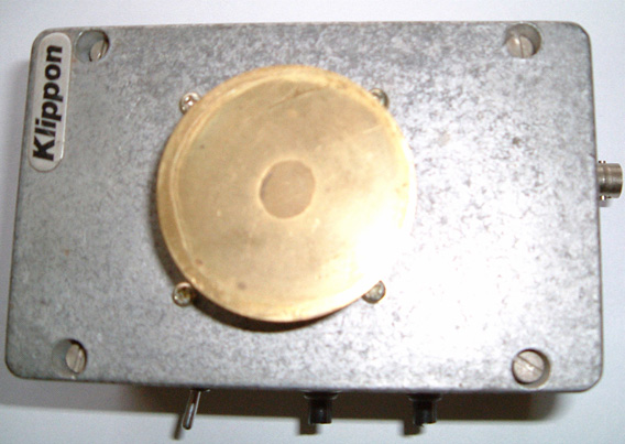 The theory of operation was put forward by Gregory Hodowanec in the April 1986 issue of the Radio-Electronics Magazine, where he puts forward the theory that the source of noise in electronic devices is caused by gravitational waves and he suggests that there are monopole gravity waves. This does not oppose the gravity waves predicted by Einstein. Gregory views these monopole gravity waves as being much stronger than those suggested by Einstein, and consequently, much easier to detect. He also suggests that monopole gravity waves have been seen for many years and have been described as “1/f noise” signals or “flicker noise”. These signals have also been called Microwave Background Radiation, supposedly caused by the “Big-Bang” though this cause is disputed by some. Gregory views our universe as a finite, spherical, closed system, i.e. a black body. Monopole gravity waves propagate in Planck time so their effects appear everywhere almost simultaneously. Gravity wave energy can be imparted to ordinary objects. So it is suggested that the fact that a fully discharged electrolytic capacitor can develop a charge when disconnected from all circuitry, is down to the interaction of the capacitor with monopole gravity waves. Gregory suggests the following circuit for examining monopole gravity waves:  Details of this and the theory can be found here. Dave has taken that circuit and extended it substantially to give added gain plus a controlled feed of white noise, without relying on the characteristics of a capacitor, capacitors being notoriously variable in precise characteristics. The unit is operated by turning the gain up until the circuit just reaches self-oscillation, and then backing the gain off very slightly. The white noise source is then adjusted until the unit is producing a somewhat echoing quality to the sound. The result is a device which has unusual characteristics. The circuitry is so simple and cheap, that you can easily try it out for yourself. The Butch Lafonte Motor / Generator. Butch has designed an intriguing Motor / Generator system based on the balancing of magnetic and electrical forces. This clever design operates according to the following statements made by Butch: 1. If a magnet is moved away from an iron-cored coil, it generates a voltage:  The voltage generated for any given magnet and speed of movement, is directly proportional to the number of turns of wire which make up the coil. 2. If a magnet is moved away from an air-cored coil, it also generates a voltage. However, the big difference is that the voltage is of the opposite polarity. In other words, the plus and minus connections are swapped over:  Again, the voltage generated for any given magnet and speed of movement, is directly proportional to the number of turns of wire which make up the coil. So, if these two arrangements are joined together, they produce a system where the voltages cancel each other exactly, provided that the number of turns in each coil are adjusted to produce exactly the same voltages. The mechanical attraction and repulsion forces also balance, so the circuit can be arranged to have no net effect when the rotor is rotated:  It follows then, that this motor arrangement could be introduced into an existing circuit without affecting the operation of that circuit. The arrangement would look like this:  Here, there is no net electrical or magnetic drag on the rotor as the magnets move away from the coils. The battery supplies current to the load in the normal way and rotor arrangement has no effect on the operation of the circuit. However, when the rotor reaches 100o or so, past the coils, the On/Off switch can be opened. This leaves the rotor in an unbalanced condition, with there being an attraction between one magnet and the iron core of one coil. There is no matching repulsion between the other magnet and the air core of the other coil. This produces a rotational force on the rotor shaft, keeping it spinning and providing useful mechanical power which can be used to generate additional power. This extra mechanical power is effectively free, as the original circuit is not affected by the inclusion of the rotor system. From a practical point of view, to give high rotational speed and long reliable life, the On/Off switch would need to be an FET transistor with electronic timing related to the rotor position. There is no need for the rotor to have only two magnets. It would be more efficient if it had four:  Or better still, eight:  And if you are going to have eight, there is no need to have the V-shaped cut-outs which just create turbulence when spinning, so make the rotor circular:  And the stator supporting the coils matches the rotor:  Ferrite is a better material for the cores of the coils. The stators go each side of the rotors and the hole in the middle of the stators is to give clearance for the shaft on which the rotors are mounted:  A system of this type needs accurate timing which is solely related to the rate of rotation. This is best arranged by the use of a bistable multivibrator as described in the Electronics Tutorial of Chapter 12. You will notice the two Timing Coils shown at the right hand side of the diagram above. These are used to toggle the bistable On and Off and they are adjustable in position so that both the On and the Off can be set very precisely. The output of the bistable is set to switch an FET transistor On and Off to give circuit switching which is not affected by either the switching rate or the number of times the switch is operated. The Rotor / Stator combination can be wired to act as either a driving Motor or an electrical Generator. The difference is the addition of one diode:  With this arrangement, for each rotor, all four pairs of Cored coils are wired in parallel across each other, and all four Air-cored coils are wired in parallel across each other. To improve the clarity, the above diagram shows only one of the four pairs, but in reality, there will be four wires coming into the left hand side of each of the screw terminals.  Further details of this Motor / Generator can be seen here. The Joseph Newman Motor. Joseph Newman is a man who impresses me. He performs experiments, reports the results and then bases theoretical conclusions on the results of his own experiments. This is the true scientific method.  Joseph has been granted a patent and he has written a book. I would recommend that you buy a copy of his book and help support his work by doing that, but unfortunately, as I understand it, the printing plates for the book were destroyed in a fire and printed copies of his book are effectively unobtainable. You can download a .pdf version from the www.free-energy-info.co.uk web site but please be aware that the overall file size is 100 Mb and so the download will take quite some time. A background download can be had from here or alternatively here while the link to Joseph’s own web site is here. In very brief outline, Joseph has built a motor which can access free energy. He has a theory about where the excess energy is coming from and how it is acquired by his designs. He has also built a large stationary motor to demonstrate his theory and he has built a motor into a car. The car engine runs on very minor battery power and can be seen here. Joseph’s patent is included in the Appendix of the eBook. With the kind permission of the Joseph Newman organisation, I am going to attempt to introduce you to the important scientific conclusions reached by Joseph and the Energy Machine which he designed and which is based on those conclusions. Joseph has a keen enquiring mind and thinks things through for himself rather than blindly accepting everything he is told. This description contains illustrations and wording taken from parts of Joseph’s book published in 1984, and I should like to express my thanks for being given permission to use this material. Joseph Newman’s motors all consist of a very powerful permanent magnet which rotates or oscillates in or near a coil with a very large number of turns of copper wire. The coil is energised by a battery pack, and the magnetic field produced by the coil provides the force needed to move the permanent magnet. A mechanical switching device or “commutator” reverses the direction of current flow through the coil every half cycle, and in some models, it also cuts off the current input between the current reversals. The main difference between Joseph’s designs and previous motors is one of scale as Joseph uses very large coils and very large ceramic magnets weighing up to 700 pounds. His smaller motors use powerful rare earth magnets and the coils are wound with 100,000 turns of copper wire. This creates a very high coil resistance and the battery pack voltages are correspondingly high, being in the hundreds to thousands of volts range. The torque or turning power applied to the magnet in these motors is proportional to the magnet strength, the number of turns in the coil and the current flowing in the coil. In Joseph’s motors, very large torques can be developed by very small currents. In one demonstration, a motor running on 3,000 volts at 0.8 milliamps has such power that it is not possible to stop the motor by holding its two-inch (50 mm) diameter shaft, though the current can be raised by trying to stop it, to 3 milliamps, or nine watts of power. Joseph’s motors are different in other ways. If fluorescent tubes are connected across the motor coil, they light up due to the coil’s collapsing magnetic field each time the current direction is switched. These fluorescent tubes are used to protect the mechanical switch from arcing damage. The additional power produced in these tubes is at a very high frequency of 10 to 20 MHz. This radio-frequency current has been accurately measured and it exceeds the battery input current by a factor of five to ten times in the different motors. The measured current and voltage were in phase, indicating a real power output. To understand the thinking behind these motors, we need to follow Joseph’s experiments and the deductions which he made from those experimental results. Joseph considered, and thought carefully about statements made by the two scientific giants James Clerk Maxwell and Michael Faraday, and this led him to valuable insights: It appears that Maxwell and Faraday were the only people who considered that “lines” of magnetic force are actual physical entities and not just a method of representing notional forces and those “lines of force” are actually streams of matter in motion. Maxwell says: “In speaking of the Energy of the field, however, I wish to be understood literally. All energy is the same as mechanical energy, whether it exists in the form of motion or in that of elasticity, or in any other form. The energy in electromagnetic phenomena is mechanical energy”. Joseph then considered Michael Faraday’s Electrical Generator and the implications of the way in which it operated:  Here, a loop of wire is moved downwards from level “A” to level “B”. This movement causes an electrical current to flow leftwards along the wire as shown by the red arrows. Joseph’s question was “why does it go in that direction every time the wire is moved in that way?”  If the wire is moved upwards through the same magnetic field, then the current flowing in the wire moves in the opposite direction. Why? How does the current “know” which way to go?  If you turn the magnetic field round by reversing the position of the magnetic fields and then move the wire loop in the same way as before, the current flows in the opposite direction. How does the current “know” which way to flow, or which way round the magnets are turned as it does not touch them?  The next interesting point is that if the wire loop is moved up and down between the magnets, but turned to be parallel to the flux flowing between the poles, then no current flows in the wire, no matter how quickly the wire is moved up and down.  Another point is that if the wire loop is moved slowly up through the magnetic flux, the electric current which flows as a result of that slow movement, moves at the speed of light, flowing from “A” towards “B”.  Now, if the wire loop is disconnected and turned over, the part which was at “A” now moved to “B”, and the same movement of the wire carried out - the current flow is in exactly the same direction although its path along the wire is reversed (because the wire has been reversed). This shows that the direction of current flow is not affected by the wire itself. According to conventional teachings, this electric current flow was not a result of the magnetic field as the magnetic lines of force were supposed to be imaginary, consisting of Potential Energy and no Kinetic Energy. It became clear to Joseph that this conventional teaching was wrong. Instead, it seemed clear that the magnetic field consists of particles which have mechanical characteristics, and those particles must be moving at the speed of light within the magnetic field. A key question seemed to be: “how does the current ‘know’ which direction to flow?” as the direction was always consistent. After careful consideration, it occurred to Joseph that the answer was provided by the actions of a gyroscope:  Here, if the axle of the spinning flywheel, or gyroscope, is pressed downwards it moves off in the direction shown by the red arrows. However, if the axle is pressed upwards:  then the axle moves in the opposite direction as shown by the red arrows. This effect is, of course, reversed if the direction of rotation of the gyroscope is reversed (as it will be if viewed from the other side, in the same way as the current flow direction in the wire is reversed if the magnetic poles are swapped over). Now, if the gyroscope axle is moved up and down equally on both sides, there is no resulting sideways force:  The action of the gyroscope axle matched the current flow in the wire in every respect, so it became clear to Joseph that the particles flowing between the poles of the magnet were spinning as well as moving at the speed of light. This gyroscopic mechanical motion of the particles accounts for all of the characteristics of the current flow in a wire which is being moved through a magnetic field. This is a major insight on the part of Joseph. May I remark that these particles are not coming from the magnet itself, but are flowing in from the zero-point energy field, that flow being caused by the broken symmetry of the zero-point energy field generated by the dipole effect of the poles of the magnet. That is why energy can (appear to) be drawn from magnets for years on end. Joseph then went on to consider the physical aspects of permanent magnets. There were two very significant facts which had to be considered. The first of these is that different materials have markedly different magnetic characteristics:  A bar of soft iron does become a permanent magnet when pulsed briefly with a strong magnetic field, but if exactly the same level of magnetic pulsing is applied to a similar bar of an alloy of iron, nickel and cobalt, a permanent magnet is also produced, but the magnetic field of the alloy is very much stronger than that of the soft iron bar. This shows that the molecular structure of the bar has a major effect on the resulting magnet. In passing, please be aware that the more powerful magnets available nowadays are so strong that they can easily injure you. If you pick up a magnet and inadvertently get close to a second one, the loose magnet will jump some inches and try to connect to the one in your hand, crushing your fingers in the process and proving very hard indeed to shift in order to deal with the injury. I have also seen it alleged that US ‘AlNiCo’ (Aluminium / Nickel / Cobalt alloy) magnets are deliberately doped with K40 isotope which renders them useless fairly quickly. The source of this information is highly dubious, but the extra sales advantages to the magnet manufacturers would be significant. Also, the advantages for the people wanting to suppress the creation of free-energy magnet motors would be major as many talented US inventors are likely to think that their successful magnet motors were failures because the magnets appeared to be “drained of power” by being used in their design, when in fact, the design is perfectly good. So I will leave you to make up your own mind about the matter and remark that Bill Muller found that his powerful Chinese-manufactured magnets were in perfect condition after eleven years of use. Another point which Joseph considered was the fact that when successive magnetic pulses are applied to a ferromagnetic metal bar, the resulting magnetic field strength reaches a definite maximum value, and further pulsing has no further beneficial effect:  This is considered to be the magnetic pulse aligning atoms in the metal. Eventually, all of the atoms are aligned and so not further effect can be produced by further pulsing. This alignment can be destroyed if the metal bar is heated to a sufficiently high temperature, forcing the atoms into such an energetic state that the alignment is lost. It should perhaps, be stressed here, that the magnet itself does not have any power, in spite of seeming to have. Tom Bearden explains this clearly by pointing out that what happens is that the opposite poles of the magnet created a “dipole” which unbalances the random ‘quantum foam’ nature of the local environment (the zero-point energy field) and that causes continuous energy flows from the environment. The “magnet” power is coming from the environment and not from the magnet itself. If you find this hard to believe and think that you are just getting back the electromagnetic energy which you pumped into the metal when creating the magnet in the first place, then apply simple arithmetic. Assume that you get back exactly 100% of the original power and calculate how long that amount of power would allow the magnet support its own weight against gravity, when attached to a vertical metal surface. Then ask yourself how come the magnet can do it for years and years on end. Point proved conclusively? Joseph concluded that the attraction of “unlike” magnetic poles and the repulsion of “like” poles is caused by the gyroscopic spin direction of the actual physical streams of the “lines of force”, which he has shown that both of the scientific giants, Maxwell and Faraday were convinced were actual physical entities. The intuitive genius Nikola Tesla described the zero-point energy field as having the physical characteristics of a gas, capable of having motion, exerting pressure, and yet having particle size so small that it can flow through any physical material. Joseph has concluded that this field flow has a specific spin direction as it flows, certainly for flows caused by the magnetic dipole of a magnet. It should be remembered that the scientific teaching of present day educational institutions is at least fifty years out of date. We have the most unusual situation where the scientific literature of a hundred years ago is actually of better quality than that of today which does not describe the actual world at all well. Currently, misconception is alive and very well. For example, Maxwell produced equations describing how the world works. Admittedly, these equations are very difficult for people to understand. H. A. Lorentz simplified these equations and his results are mistakenly described as Maxwell’s which they most certainly are not. Tom Beardon illustrates it this way; consider a sailing boat being driven along by the force of the wind against the sails:  Maxwell says that there is a vast swathe of wind blowing across the ocean, capable of powering a long row of a thousand sailing boats side by side. This is the actual physical case. Lorentz has ‘simplified’ things by saying “we will consider one boat and only one boat. As the rest of the wind does not touch any part of the boat we can ignore it”. While that is true for that one boat, what science teaching now says is that the wind can only power a single boat. This is not the actual case, as the environmental wind is not limited to powering just one boat (sailing regattas would not be much fun if that were the case!). This, of course, is just an illustration. Maxwell’s equations cover energy and power for the whole universe, and deal with all cases. Lorentz has taken a sub-set of the conditions described by Maxwell’s equations, just the group which apply to “closed systems” – just one boat on the ocean. Science has latched on to this and now confidently states that everything is a “closed” system, when in fact, as the zero-point energy field flows through everything, everywhere at all times, and is capable of supplying unlimited additional energy anywhere at any time, there is probably not a single instance of a “closed” system anywhere in the universe. Joseph Newman, and all other serious inventors, have to fight against this “conventional” science teaching, which is now so entrenched that it has become the equivalent of religious dogma, and ‘scientists’ are unwilling to consider valid observations which do not fit in with the very limited Lorentz concept of the environment. They say “perpetual motion is impossible” which means that Newton was wrong when he said that a moving body will keep on moving indefinitely unless some force acts on it to stop it. Presumably, then, the Earth can’t keep on orbiting the Sun (gosh, I hope it doesn’t stop today as that would be very awkward). Come on – get real !! You can see then, that when Joseph performs tests and then bases his conclusions on the results of those tests, that he is applying the true scientific method, and people who say that his verified results are impossible because Lorentz says so, are not being scientifically honest. No honest person can ignore genuine scientific observations. Joseph’s deduction that magnetic lines of force are formed of actual physical particles spinning in gyroscopic motion as they move along their magnetic path at the speed of light, was not something which was obvious to scientists, in spite of the fact that both Maxwell and Faraday had both explicitly described these lines of force as being ‘kinetic magnetic energy’:  As a wire passes in front of and across the end of a bar magnet, the current flows in one direction, pauses, and then flows in the opposite direction. This occurs due to the gyroscopic flow direction of the particles. For instance, on one side of the South end of the magnet, the lines of force spin “up” while on the other side of that same South end, they spin “down”. A spinning gyroscope will move at right angles to the force acting on it, so as the gyroscopically spinning particles encounter the particles of the wire, they move “up” or “down” the wire at right angles to the direction in which they first encounter the wire. Please note that it is the gyroscopic spin direction of the particles which determines magnetic ‘attraction’ or ‘repulsion’ and not the direction of flow of those particles along their line of force:  It should also be realised that although we draw ‘lines’ of force around a magnetic device, the reality is that these are really shells of force and the magnetic flow is really like water flowing in a river. While we may draw arrows to indicate direction and strength of currents in a diagram of the river, the reality is, of course, that there is water flowing at all points in the river and not just along the lines which we decide to draw. The same applies to the magnetic flow around a magnet, it exists like a solid mass flowing through and around the magnet. You don’t see it or feel it because the particles are so small. Now to the details of how to construct a device to take advantage of this magnetic movement and output more power than is required to make it operate. Let me remind you again that we are talking here of a Coefficient of Performance (COP) which is greater than 1 in a system which has an overall power efficiency of less than 100%. This is, of course, due to the additional energy flowing in from the zero-point energy field. Joseph visualises the apparent energy gain as being conversion of a small amount of matter into its energy form (E = mC2), and while this is probably correct, it will be particles of the zero-point energy field which are being converted into their energy form and not particles from the metal of the magnet. It must be remembered that the particles of the zero-point energy field keep swapping over from energy to physical form all the time anyway. Energy is never “used up” but merely converted from one form to another and the zero-point energy field contains such a staggering amount of energy that all of the visible matter in the whole of the universe could be created from the energy in a single cc of the zero-point energy field. So, if a few sub-sub-sub-microscopic particles of the zero-point energy field switch into their energy form to produce what looks like excess power to us, that is an item so trivial to the field that it is not even worth mentioning – less than the effect of taking one grain of sand off a beach one hundred miles long. The conventional conception of the way things are is so far away from reality that it is ridiculous, (and that is even without saying anything about the effect that the time axis dimension has on the energy balance and flow of energy). But back to Joseph’s design. Firstly, he points out that it is generally agreed (courtesy of Gustav Kirchhoff) that in the situation shown here:  in any given instant of time, the amount of current flowing into the system (“X”) is exactly matched by the amount of current flowing out of the system (“X”). But, if measuring equipment is attached across the coil at the moment of switch-off, an additional amount of current (“X”) flows out of the coil. This is generally agreed, and it suggests that a quantity of current “X” flows into the coil and yet a quantity of “2X” flows out of it (COP=2). Joseph examines this situation in practical detail as follows:  Consider an air-cored coil with an interior diameter of 10 feet, a height of 8.32 feet and would with 1,000 feet of 40-gauge copper wire. That length of wire has a resistance of 1,049 ohms and weighs 0.02993 pounds. If 100 volts DC is connected across it, then a current of about 95 milliamps will flow, which is a power input of 9.5 watts. With just 31.8 turns, it will produce a weak magnetic field of 0,012 Gauss, with a mere 0.000014 Joules of energy stored in it. With a tiny inductance of just 0.003 Henries, if the current is stopped and the ends of the coil shorted together, only an insignificant current would flow. Now, repeat the experiment, but this time, use 5-gauge copper wire. As it has a resistance of 0.3133 ohms per 1,000 foot length. To equal the same resistance and match the previous current flow, a massive length of 3,348,000 feet needs to be used. This length of wire will weigh 335,469.6 pounds which is 16.77 tons. The 10-foot interior diameter coil, 8.32 feet tall, wound with this wire will have about 90,000 turns. If 100 volts DC is now connected across the coil, the same 95 milliamp current will flow with an input power of 9.5 watts, the same as before. But due to the massively larger coil, it has a magnetic field of 23.7 Gauss, which is 1,905 times larger than the previous coil, and with 116 Joules of energy stored in the magnetic field. This is a phenomenal 8,000,000 times more energy than in the 40-gauge coil of the previous example. A phenomenally larger current flow would now occur if the current input was stopped and the coil shorted out, as that would generate an inductance of 25,700 Henries which is more than eight million times the inductance of the previous coil:  Joseph then built a smaller version of his design, as shown here: 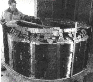 this prototype used 5-gauge insulated copper wire weighing 4,200 pounds and 300 pounds of 30-gauge copper wire wound over the 5-gauge winding, and a massive 4-foot long, 20-inch diameter permanent magnet of some 600 pounds in weight. The coil was wound with an inner diameter of 4-feet and a height of about 3-feet, wound on a fibreglass tube. The overall weight was about 5,000 pounds. Everybody who was it was asked: “Based on your expertise, how much power would be necessary to simply operate this device mechanically?”. Answers ranged from 200 watts to 1,000 watts. On learning that it had an air-cored coil, other skilled individuals stated that in their expert opinion, the unit would be highly inefficient since it contained no iron core. However, from the design information already presented here, it can be shown that the actual necessary power input is less than 1.5 watts providing a power output far in excess of 100%. Dr. Roger Hastings, Principle Physicist at Sperry Univac Corporation and former Associate Professor of Physics at North Dakota State University, tested this prototype and showed that it had an 800% efficiency – that is a Coefficient of Performance of 8.0 which is impressive. In addition, Dr Hastings estimated that with a 1.5 watt power input, the back emf exceeded 80,000 watts. In operation, the 600-pound, hand-made magnet rotates at just 200 rpm. Joseph’s patent which is in the Appendix of the eBook, indicates four different ways of implementing his design principles. It is very clear that Joseph has proved his point by producing and constructing a device which Lorentz considered to be impossible, thanks to his throwing out the free-energy sections of Maxwell’s equations. Joseph Newman has clearly earned our respect. Daniel Cook. In 1871, Daniel Cook obtained US Patent 118,825 for “An Improvement In Induction Coils”. It is by no means obvious how the device described could possibly operate, and it has been suggested that the patent information is incomplete having been edited at a later date. But as I have no direct evidence that it does not, or cannot, operate, it is shown here. Interestingly, the highly-respected Dr Harold Aspden considers this a very serious piece of equipment, operating as paired cross-linked capacitors, and his opinion carries very considerable weight. It is a very simple device which could be interesting to test, especially as it does not involve any electronics or complicated construction. The patent can be summarised as follows: My invention relates to the combination of two or more, simple or compound, helical coils with iron cores or magnets, in such a manner as to produce a constant electric current without the aid of a battery. Fig.1 represents the different parts of a compound helical coil and iron core.  Fig.2 is a perspective view of my invention.  In carrying out my invention, I do not confine myself to any particular mode of coil construction or to any particular size of wire, observing only that the quantity of wire in the various coils must be sufficient to produce the required result; also, the material used to insulate the wires must be suitable for producing the required result. However, I generally prefer to use the same size of wire in the construction of both simple and compound coils. When constructing simple coils, to produce the required voltage and current, it is desirable to use a long iron core as shown as A in Fig.1. This iron core may be two, three or even six feet in length, and two, three or more inches in diameter. The coil should be wound from good quality copper wire, insulated with silk or shellac. The iron core A may be a solid bar or a bundle of separate iron wires, the latter giving better results and providing more current for any given wire diameter. While the wire may be fine or coarse, I prefer to use No. 16 or even heavier wire, as the power output is in proportion to the length and diameter of the wire. When using compound coils, it is preferable in some cases to use a small wire, say, No. 30 or even less, for the primary coil, and No. 16 or even larger for the secondary coil. With this combination, the initial secondary current of the primary coil being very small in comparison to the terminal secondary current of the secondary coil, offers little resistance to the terminal secondary, hence a quicker action is obtained. Alternatively, the primary coil may be of uninsulated wire coiled into a solid helix, being insulated only between the coils, in which case there is little or no opposing initial secondary current. Helically wound coils alone with large quantities of wire will produce similar results. A ribbon spiral may be substituted for the secondary coil C, say, of three, six, twelve or twenty-four inches in width and of any convenient length, but always of sufficient length to raise its output current to the level necessary to sustain itself through its action on the primary coil B. In the use of compound coils, it is important that the secondary coil should be wound in the same direction as the primary coil, and the primary and secondary coils be cross-connected as shown in Fig.2. The action will then be as follows: The secondary current of the secondary coil C, will circulate through the opposite primary coil B, while at the same instant, a secondary current from the primary coil B will be generated and circulate through the opposite secondary coil C, both currents flowing in the same direction in the opposite coils B and C, producing a combined magnetic action on the iron core A in the centre. The opposing initial secondary currents of the two coils B and C being overpowered, do not show in the main circuit D of the device, there being eight distinct currents developed in the action of one entire circuit of the two pairs of coils, two terminal and two initial secondary currents to each pair of coils, the four initial secondaries constantly opposing the circulation of the four terminal secondary currents, but the initial secondaries being of much lower voltage and current than those of the terminal secondary, are overcome, leaving a sufficient surplus terminal power to overcome the resistance of the primary wire and charge the bar A to the degree needed to reproduce itself in the opposite secondary coil. By this means, a constant current is kept flowing in all of the coils. These coils may be constructed using 500 feet to 1,000 feet or more for each of the primary and secondary coils. The longer, and better insulated the wire, the greater is the power obtained from the device. The larger the wire diameter, the greater the current obtained. If only single coils are to be used, it is preferable to have a wire length of 1,000 feet or more in each coil. The action is the same as with the compound coils, but only four currents are produced: two initial and two terminal currents, the latter flowing constantly in the same direction - in effect, there being only one current in the same direction. The action in the coils may be started by using a permanent magnet, an electromagnet or by pulsing an extra coil wound around the outside of one of the coils of the device. If the load circuit is broken for any reason, the current stops immediately. It is then necessary to perform the start-up procedure again to get the device restarted. This can be overcome by permanently connecting a resistor across the terminal of the load so that if the load circuit is broken, the device can continue under very much reduced current until the load is restored. By this means, the device becomes the direct equivalent of a battery. A rheostat D may be introduced into the main circuit to limit the current and prevent the overheating of the coils through the drawing of excessive amounts of current. The iron cores may also be used for producing electromagnetic motion when the device is operating. Note: Interesting replication attempts are shown here. Michael Eskeli. One of the greatest expenses for most families is the cost of heating or cooling a home. Any device which can help with this task is definitely welcome. Michael Eskeli has produced several most interesting designs which may have been overlooked due to lack of emphasis of what they do. Normally, a central heating system uses an expensive method of heating a liquid, typically oil, which is then pumped through radiators around the building by a low energy pump. The vast majority of the cost is in heating, typically, a furnace and very little is spent on moving the heated liquid through the radiators. In this design from Michael, the cost of the heating is zero, and all that is left is a low-power (quarter to half horsepower) input, needed for spinning a rotor against the friction of its bearings and stuffing box. As this seems impossible, a little very technical explanation is given here. This information has come from the web site of Scott Robertson with his kind permission. In broad outline, the device comprises of a disc-shaped housing with a closely-fitting rotor spinning inside it. A gas under pressure and a liquid under pressure are both fed into the device and they intermingle in a pulsating sequence which alternately compresses and releases the pressure on both fluids. This heats both fluids very effectively, and most interestingly, without the use of any user-supplied heating power and without the use of any heating fuel. This next paragraph is for Engineers, so if you don’t understand it, then just ignore it, as the important thing is to understand what the device does, rather than exactly how it does it.  The Heat-Pump Work Cycle: The example diagram above shows the sequence of events caused by the rotation of the disc inside the device housing. This “Pressure / Enthalpy” or “Pressure / Internal-Energy” diagram shows the pressures and temperatures during a single pressure cycle of the device. Using nitrogen as the gas, the cycle starts at point “1” which has a pressure of 150 psi and a temperature of sixty degrees F. A pressure wave now hits the mix of nitrogen and the liquid. This pressure wave moves us to point “2” where the pressure has been boosted to 540 psi which raises the temperature to 280 degrees F. Moving to point “3” is where the wanted heat is passed throughout the gas a the liquid (performing the heating task which is the whole object of the exercise), even though the pressure is maintained, so at point 3 there is a pressure of 540 psi and a temperature of 138 degrees F. Next, comes a major drop in pressure, taking us to point “4” pulling the temperature down to below freezing: 250 psi at just 4 degrees F. At point “5” the pressure is dropped further to 150 psi, still at 4 degrees F. Point “6” takes us to 250 psi at 60 degrees F from where the cycle takes us back to point “1”, and the sequence starts all over again. The compression takes place on leg 1 to 2 and leg 5 to 6. The actual amounts are 53.2 and 13.5 respectively, giving a Compression Total of 66.7 B/lb. The expansion takes place on leg 3 to 4, leg 4 to 5, and leg 6 to 1. The actual amounts are 31.6, 16.6 and 18.7 respectively, giving an Expansion Total of 67.0 B/lb. As these two are virtually identical, the overall result of a complete cycle is effectively work-free. This work cycle can be readily performed by the Centrifuge-Type Heat Pump. This is a unit which has only one moving part, the rotor, the working fluid, such as nitrogen, is sealed in with the rotor and circulates in passages in the rotor. The circulation of the working fluid inside the rotor is accomplished by density control alone, in accordance with the work-cycle shown above, and there is no work input to the working fluid from the rotor shaft. Thus the work input for the heat transfer is nil, and a work-free heat pump results. In the diagram shown below, an axial cross-section and an end view with sections removed, shows a typical heat pump rotor suitable for use with the work-cycle discussed above. In the diagram, 10 is the heated-fluid heat exchanger, 11 is the heat-supply heat exchanger in two parts, and 12 are the vanes in passages which return the working fluid from the periphery to the centre of the disc. The work cycle process is of the non-flow type for the working fluid in this rotor, and this provides higher performance that that in the example shown above.  The fluid to be heated is usually a liquid, such as water, which enters and leaves the rotor via the rotor shaft. Similarly, the heat-supply fluid circulating through heat exchanger 11, is a liquid which enters and leaves via rotor shaft passages. The work-free heat pump obviously has many uses. One such use is in heating all types of buildings and homes, resulting in cost-free heating, since no fuel is needed, and the power usage is nearly nil. In the heat pump shown above, power is needed to drive the rotor against friction which may require a quarter to half horsepower motor. Another use is in power generation, resulting in cost-free power since the unit uses no fuel, the energy source being either ambient air, or water from some natural source. (Attached turbine generates the power; part of this is used to overcome the heat pump friction loss and the remainder is available for generation of electricity). Further uses are in portable power and transportation vehicles, etc. The apparatus and methods and work cycles are patented. For basic heat pump, see US Patent 3,926,010 and Canadian Patent 984,827. Michael Eskeli. Here is one of Michael’s many patents: US Patent 3,650,636 21st March 1972 Inventor: Michael Eskeli ROTARY GAS COMPRESSOR ABSTRACT Method and apparatus for a compressor for compressing air, gases and vapours isothermally using a liquid stream to compress the gas; the liquid issuing from an impeller intermittently, with the gas being entrained between these liquid pulses and compressed by the liquid; the liquid having high kinetic energy when leaving the impeller and in slowing the kinetic energy is converted to pressure for both the liquid and entrained gas. Also, this compressor may be used advantageously to compress vapours, wherein the liquid is the same fluid as the gas, in which case condensation of the gas to the liquid occurs, and work of compression is reduced.  BACKGROUND OF THE INVENTION This invention relates generally to devices for compressing gases, air and vapours, in which a liquid is in intimate contact with the gas or vapour to be compressed. DESCRIPTION OF PRIOR ART There are numerous devices and machines available for compressing a gas or a vapour. In some of these machines a liquid is rotated inside an eccentric casing, so that the machine rotor will cause the liquid to pulsate and the space between the rotor blades is increased or decreased, and this variation compresses the gas. These machines are called liquid piston type machines. Another device is the jet ejector compressor, where a stream of liquid or gas is used to entrain the gas or vapour to be compressed, and the kinetic energy of the stream is converted in a diverging nozzle to a pressure. The main disadvantage of the liquid piston type machine is its poor efficiency, since the liquid is rotated in the machine and requires relatively large power input for compressing the gas. In the ejector compressor, the velocity of the liquid stream is limited and it entrains poorly of any gas; therefore the efficiency of the device is very poor. The available kinetic energy in the liquid stream is high, but due to poor entrainment of the gas by the liquid, results for the device are poor. BRIEF DESCRIPTION OF THE DRAWINGS  Fig.1 is an end view of the compressor casing, showing the exterior.  Fig.2 is a side view and a section of the casing and the impeller of the compressor.  Fig.3 is a side view and a section of the impeller, and  Fig.4 is an end view of the impeller, showing the fluid passages. DESCRIPTION OF PREFERRED EMBODIMENTS It is an object of this invention to provide a method and a device for compressing gases or vapours essentially isothermally in which the kinetic energy contained by a liquid stream is used to compress said gas to a higher pressure where the liquid in slowing in speed will increase its pressure and increase the pressure of the gas being entrained in it. Also, it is an object of this invention to provide a method and a device in which the gas may be partially or fully be condensed in the liquid stream thereby lowering the work of compression; this occurring when the gas or vapour being compressed is the same fluid as the liquid; that is, the gas being compressed is the vapour phase of the fluid, and the liquid being used for as the motive fluid is the liquid phase of the fluid. Referring to Fig.1, there is shown an end view of the compressor, where 10 is the compressor casing, 11 is the liquid inlet, 12 is the gas or vapour inlet, and 13 is the outlet.  In Fig.2, a side view of the compressor is shown. The impeller 22 is rotated by shaft 28, supported by bearings and sealed by packing 23 and stuffing box 24. Alternately a mechanical seal could be used. The liquid that is used as the motive fluid enters through opening 11, passes through the impeller 22 and leaves the impeller at a high velocity and entering the throat section 21 and from there the diffuser section 29 in the casing 10. After leaving the diffuser at a higher pressure, and at a lower velocity, the gas and liquid mixture is collected in annular space 30, and from there passes out through opening 13. The liquid entrains gas from annular space 31, and the gas enters the annular space from outside through opening 12.  In Fig.3, the impeller 22 is shown in more detail, where 38 is the fluid passage, and 36 is the opening for the drive shaft. In Fig.4, the impeller is shown, with 22 being the impeller and 38 being the fluid passage. In operation, the compressor functions in a manner similar to a jet ejector compressor. A motive fluid is accelerated in a passage in the impeller to a high velocity; this corresponds to the motive fluid nozzle in a jet ejector. However, the fluid stream issuing from the impeller, when it rotates, is not continuous as seen by the compressor casing, since in this particular instance, the impeller has four fluid passages, with solid material between them. Therefore, the flow from impeller, as seen by the compressor casing, is pulsating, with empty spaces between the high speed liquid; these empty spaces being filled by the gas from the annular spaces, item 31, Fig.2, and the gas being rapidly moved with the liquid to the outer annular space 30, and from there to discharge. This pulsating action improves the entrainment of the gas by the liquid, and more fully utilises the kinetic energy available in the liquid stream. The sizing of the fluid passages and the calculations related to them, are fully described in thermodynamics literature for jet ejectors and for steam injectors. The space of the passage 38 in Fig.3, would be either converging for liquids that do not vaporise when leaving the passage; or the passage could be diverging at its outlet for fluids which will vaporise either partially or fully when leaving the passage. Of the non-vaporising liquids, water would be an example, and of the partially vaporising types, butane would be an example, both at atmospheric temperatures, and at low pressures. As illustrated in Figs. 2-4, passageways 38 comprise a converging section nearest the centre of the impeller but are at least non-converging at the discharge section. Preferably, the at least non-converging section is a diverging section for better taking advantage of the energy available in the motive fluid to achieve higher exit velocities. The fluid passages shown in Fig.4, item 38, can be radial as illustrated, or be forward or backward curved, depending on the fluid used. Also, the throat section 21, of Fig.2, may have vanes of proper shape to prevent circular motion of the fluid after it leaves the impeller. Vanes of this type are commonly used in turbines and pumps and so are not described here. There are four fluid passages shown in Fig.4, but this number will be determined when calculations are made for the size of the passages, and the frequency of pulses of liquid required to maintain suitable pressure and volume relationships inside the compressor; also, the rotational speed of the impeller would enter into these calculations. Normally, the amount of liquid is large when compared to the amount of gas or vapour. Therefore, when compressing a gas, the heat of compression from the gas is transferred to the liquid, resulting in a temperature increase of the liquid, as well as of the gas. This temperature increase is much less than it would be for the gas alone, resulting in nearly isothermal compression, and therefore reduced work of compression, as compared to isentropic compression which is often used in rotary compressors. Also, if a liquid that will expand in the impeller is used, with an expanding fluid passage, the temperature of the motive fluid is lowered, and the fluid velocity greatly increased, resulting in much better efficiency for the compressor; this is similar to the function of converging-diverging diverging nozzles in jet ejectors. The operation of the compressor may be inferred from the above descriptive matter. A liquid source is connected to the impeller inlet Fig.1, 11 and a gas or vapour source is connected to the gas inlet Fig.1, 12. Discharge from the compressor is from Fig.1, 13. A suitable power source, such as an electric motor, is connected to shaft Fig.2, 28, causing the shaft to rotate. The liquid is accelerated by the action of the impeller, and as it passes through the annular space Fig.2, 31 in a pulsating flow, it entrains the gas and carries it to annular space 30, from where it discharges. Materials of construction for the compressor would be similar to those used to make pumps for pumping liquids. Cast iron, steel, bronze, brass, stainless steel and various plastics could be used. CLAIMS What is claimed new is as follows 1. A machine for compressing gaseous fluid and having the major components of: 2. The machine of claim 1 wherein said at least non-converging section is diverging. Karl Schappeller. There have been a number of quite outstanding men who have had great insight as to how the universe is and how it operates. One of these is Karl Schappeller who is virtually unknown. One of the reasons for this is the fact that publicising his work has been strongly opposed by people who do not want his understanding to become widely known. One device produced by Karl in order to prove that his understanding of things was correct, produced substantial amounts of excess energy, and while I do not know of anybody who has replicated his device, I am including here, a short presentation on the subject, written by Henry Stevens web site and the book by Cyril Davson which he mentions, can be downloaded from here and read in full. In the presentation by Henry Stevens, he mentions UFOs or flying discs. There has been a propaganda campaign waged against the general public for more than fifty years now, with the objective of persuading people that “UFOs” are not real, and if they were, then they would be the vehicles of “little green men”. This campaign has been remarkably effective and members of the public in general will immediately dismiss flying discs as being “impossible” and not something which any sane person would consider for a moment. This attitude is based on an almost total lack of knowledge of the facts. There are at this time, large numbers of flying discs, built by humans and capable of spectacular flight abilities. There are two varieties: those which need the atmosphere to operate and those which don’t. If you feel that this is a “load of rubbish” then take a look at the following US patents:    This small selection of forty-seven patents is restricted to just those which have the well-known “flying saucer” shape. Do you seriously think that not a single one of these patents had a test prototype which flew or that they were all piloted by “little green men”? I have no interest in flying machines which need an atmosphere as they are just advanced versions of conventional aircraft. In the early 1900s, Nikola Tesla designed and built what he described as his “flying machine”. This was a small device without wings and which ‘flew’ without the use of a fuel. This design of Tesla’s was taken by the Germans and during World War II, developed and experimented with. After the war, it was taken to the USA and developed further at Groome Lake, and at this time, the US, UK, Canadian and Russian governments have got large working copies which they keep as secret as they possibly can. One major cover story is that these craft belong to “extraterrestrials” who have such an advanced level of technology that we will never be able to understand it. It is a good story, as it is not possible to disprove it. If you want a good deal of specific information on this, then read “The Hunt for Zero Point” by Janes researcher and writer Nick Cook. While I have no particular interest in electrogravitic propulsion (or "anti-gravity" as it is popularly known and incorrectly termed) if the subject interests you then take a look at the YouTube video sequence of Stan Deyo who was one of the people who developed electrogravitic propulsion for an international group, several decades ago. Stan explains "gravity" as being the product of spin affecting the space-time continuum and he shows practical mechanisms for generating a drive from this principle in his presentation here. The Karl Schappeller Device Author: Henry Stevens Karl Schappeller (1875-1947) literally went from being born in poor-house to owning a castle during his lifetime. His economic success was mirrored in his experiments in energy as a lay-scientist, culminating in the invention of a free-energy device which attracted considerable attention around 1930. Schappeller made no secret of his invention and actively sought private financing to manufacture and distribute the results of his research. He was in touch with financial concerns and he even spoke with a representative of the British Admiralty concerning the utilisation of his device to power Royal Navy's ships (1). At this time, 1930, the device was somehow appropriated and further worked upon by a governmental organisation of the German Weimar Republic, the Reichsarbeitsgemeinschaft or Reich Works Association (RAG). At least one aim of the RAG was to make Germany self-sufficient in energy production. Specifically, they published their intentions to utilise many Schappeller devices in a system of broadcast energy distribution throughout Germany which would result in the entire elimination of the electrical grid (2). As we know, Adolf Hitler assumed power three years later and for strategic reasons, he was also very interested in making Germany independent of foreign sources of energy. It is known that political and scientific structures were set up to work on the energy problem as evidenced later by the synthesising of gasoline and oil products from coal by the 3rd Reich. One of these political and scientific structures was contained within the SS and it is known that Karl Schappeller actually met with SS Reichsfueher Heinrich Himmler in Vienna in 1933 (3).  Left: Inventor Karl Schappeller Right: Karl Schappeller’s Device. A. Steel outer casing. B. Special ceramic lining in which tubes are embedded. C. Hollow centre, filled with glowing magnetism when in operation. D. Tubes, circuit and earthling. Fortunately, there are good descriptions of the Schappeller device upon which to draw in both German and English. Per Vril-Mythos is a complete discussion of Schappeller, his device, the history and the controversy surrounding it. "Vril, Die Kosmische Urkraft Wiedergeburt von Atlantis” and “Weltdynamismus Streifzuege durch technisches Neuland an Hand von biologischen Symbolen” represent an attempt by the RAG to popularise their ideas in booklet form. Finally, British electrical and mechanical engineer, Cyril W. Davson, visited Karl Schappeller in Austria and spent three years learning of his device and his theory before the Second World War. Davson's descriptive book, “The Physics of the Primary State of Matter”, was written in 1955, after the war and the death of Schappeller. Before describing the device itself it should be understood that Schappeller and all writing about his device believe that the energy-source being tapped is aether energy, sometimes called "Raumkraft" or "Raumenergie", that is space-energy (4)(5)(6). This device was also said to be capable of, perhaps with some tuning, emitting aether as a radiant energy (7). The physics of aether energy is described by Davson as “primary physics” as opposed to “conventional physics” which he believed could only be considered to be a secondary, derivative understanding. Aether Theory For readers who have never heard of "aether", perhaps the simplest explanation for aether physics is that of the late Dr. Hans A. Nieper (7) entitled “Revolution in Technology, Medicine and Society”. Aether could be thought of as an energy source emanating from everywhere equally at once. The universe could be considered, as is often said, to be "a sea of energy". It forms a background of energy everywhere, and since it is everywhere all the time, it is difficult make independent measurement of it. This aether energy is in constant motion. All energy is radiant energy, according to this theory. This can easily be appreciated as to electromagnetic radiation but it is also true of that very elusive thing called gravity. Newton described the effects of gravity but he never told us exactly what it was. Dr. Nieper tells us that gravity is really a push, and not a pull. Gravity is acceleration and is caused by the aether field. Again, all energy is radiant-energy whose fundamental basis is aether radiation. From the aforementioned book by Dr. Nieper: In addition, Nieper established the axiom that, “all natural accelerations can be attributed to a single unified basic principle, namely, the interception (or braking) of a field energy penetrating from the outside (gravity acceleration, magnetic, electromagnetic, electrostatic and radiesthesic acceleration)". In trying to explain aether, it might be thought of as an all-pervasive liquid, occupying all of space. This liquid concept is useful because a liquid can not be compressed but can only transfer the energy attempting to compress it from one location to another. This is how the brakes of a vehicle work. The driver presses the brake pedal when he wants to slow down or stop. The plunger of the brake pedal attempts to compress the liquid in the master cylinder. The master cylinder is connected to each wheel by metal tubes full of liquid. When pressure is put on the master cylinder by the driver it is transmitted to each of the four wheel cylinders full of the same fluid which transmits the force, moving the brake mechanism, slowing the wheels of the vehicle. In a similar way, the aether serves to transmit energy through this "non-compressible" quality. In a primary electric coil and secondary electric coil, for instance, induction in the secondary does not take place directly from the primary as is now said by current physics, but instead, the induction between the two windings is due to the aether field. This concept of the energy transfer function of the aether field is also expressed by Davson. Using this perspective, that all energy is radiation, the braking of aether radiation, that is the slowing down or stopping of this radiation, can cause a transfer to other forms of energy. The word "energy" means the entire electromagnetic spectrum. That includes, electric, magnetic and electrostatic fields. This means heat. This also means gravity. Again, gravity is the primary radiation of the aether field. It radiates from every point in the universe equally. This concept seems ridiculous until it is given some thought. One might ask: “How can gravity be a push when we know better?” After all, things fall to earth, don't they? The answer is that the effects which we feel and call “gravity” are due to aether shielding. Aether radiation can be braked, that is slowed down and absorbed by mass. It is then re-radiated or converted into mass. It is re-emitted as slower aether radiation or even as heat. Some of it can, and is, converted into mass inside a planet. If there is a loss of aether radiation, then there is shielding. Thus, a planet would shield from this radiation in one direction. That direction is always toward its centre which is the direction of greatest mass and that is what we describe as "down". This is simply the area which contains the maximum amount of shielding. In all other directions the aether radiation continues to exert its push on us. The area of minimum shielding is directly opposite the area of maximum shielding, so things fall (or more correctly are accelerated or "pushed") towards the earth. Think about this for a minute. Being in deep space is rather like being underwater. Underwater, the pressure at all points is so similar that we feel weightless. We are weightless in deep space because the aether field exerts a push on us from all directions equally. In space, the nearer one gets to a large body the stronger the push is from the opposite direction since the body shields or converts the aether radiation. The result of this thinking is a mechanism totally different from "gravity" as we know it but appearing as exactly the same observed phenomena. The beauty of this aether theory of gravity is that gravity functions like every other form of radiation. Its underlying cause, aether radiation, can be converted to mass or, in certain circumstances, re-radiated or converted to other forms of energy. No Unified Field Theory is necessary. The aether field is the unified field. Further, there is no need to look for something separate called "anti-gravity". If gravity is a push then it is all anti-gravity. All we have to do to make a UFO, is to find this particular gravity frequency and find out how to generate it. Aether physics was a lost physics. Physics was hijacked early in the 20th Century by the alleged results of the Michelson-Morley experiment. This experiment assumed that "aether" was matter. There is some confusion here. We know now that particles moving near the speed of light are measured as waves, that is energy, rather than as matter. Nevertheless, aether theory has been discredited among physicists who, in turn, discredit others who raise the subject. It is only through the efforts of "free-energy devices" and free- energy researchers, that this knowledge is being returned to us. Without this aether theory, the reason these devices work cannot be explained at all. Rejection of aether theory allows these devices to be dismissed as "theoretically impossible" and so “fraudulent” by implication. They are marginalised and dismissed as "perpetual-motion devices". According to established physics, perpetual-motion devices violate the physical laws of conservation of energy. Without an aether theory as an explanation, they do violate the laws of conservation of energy and so their detractors are able to simply dismiss them out of hand. The simple fact that some of these free-energy devices actually work, does not seem to bother these scientists in the least. Rather than change the theory to accommodate the observed facts, the facts are ignored and substituted by dogma. Whether we like it or not, we are living in an energy Dark Age. Instead of aether theory, we have all been led to focus upon Einstein and his Theories of Relativity. Two or three generations of scientists have wasted themselves on "trying to prove Einstein right". This misguided thinking has resulted in stagnation. One need go no further than the many "free-energy" devices which have arisen to the level of notice in spite of accepted scientific theory to see that this statement is true. Needless to say, German scientists of the Nazi period laboured under no such illusions. They never abandoned aether physics. This was the fundamental reason why field propulsion UFOs were first developed in Germany. After the Second World War two different sciences developed, both called "Physics". One was the relativity-based concept taught in schools, while the second, more esoteric type, was used secretly, by the secret government, for deep “black projects”. Structure of the Schappeller Device According to Davson's description, upon which we will rely, the Schappeller device is really composed of two separate units, the rotor and the stator. The stator is constructed as follows: Its surface is round or ball-shaped, being composed of two half-shells of steel. These half-shells contain the internal structure and are airtight. Attached at the "pole" of each half-shell is an iron bar-magnet, most of which is positioned inside the sphere. This means that the bulk of each magnet is inside the steel ball, one opposite the other. There is a space between the two bar magnets at the very centre of the sphere. An Insulating ceramic material, is placed on the inside of the steel ball, leaving a hollow central area. Within this hollow area, and around the space between the magnets, are two coils are mounted. These start at the pole of the bar magnet and finish at the centre of the sphere, with a connection leading out of the sphere to the rotor. These coils are wound using a hollow copper tube filled with a special, secret substance called the "electret". Upon leaving the sphere, the electret-filled copper tubes are replaced by conventional copper wire. An electrical connection is made from the outside surface of one pole to one pole of a special type of battery which is grounded at the other pole or, alternatively, to a special device called an "Ur-machine" which will be discussed later. This electret is a permanent magnet within the sphere. This type of magnetism is not identical with ferro-magnetism or electromagnetism, it is much stronger (8). The actual composition of Schappeller's electret remains a secret, but another electret has been made by Professor Mototaro Eguchi. It consists of carnauba wax and resin, perhaps also containing some beeswax. It was kept in a strong electric field while baking slowly until it solidified. For purposes of the production of Schappeller spheres, a complete electret manufacturing plant would have to be set up, which has no parallel in present science (9). Before being set into operation, all the air is pumped out of the hollow core of the sphere. This whole ball is mounted on a swivel mechanism so that the poles can be moved from the vertical to the horizontal. The stator is not attached to the rotor. The stator can function without the rotor and the stator is capable of producing electrical energy without the rotor. The rotor could also be used to generate additional electrical energy. The rotor consists of a steel wheel of special design fixed on the shaft to be driven, and surrounded on its outer surface by magnets which are attracted and repelled by the force of the stator. The copper wire attached to the internal electret-filled copper tubing, runs through this wheel and supplies electric power to the magnets. The magnets are hollow and filled with the same electret. There is always an odd number of magnets. A variant of this rotor comes to us from Taeufer, who refers to this further development as the "Ur-Machine". This machine is composed of six sphere units as described above, five revolving around a sixth one which is positioned either above or below the plane of the other revolving spheres. A seventh unit would be employed to rotate the five rotating spheres and so would be offset, and not attached to the others. The five rotating spheres would charge the sixth stationary sphere. The sixth and seventh spheres would function as an anode and cathode and so ground the unit. The Ur-machine could be used to activate other spheres instead of a battery-earthing procedure (10). As a prime mover, an engine, the rotor would be used to turn a drive shaft. The stator would be offset, that is, moved off centre in relation to the rotor. Schappeller worked out various angles of efficiency (11). The drive shaft could be used to power any number of machine applications such as, for instance, the propellers of a ship. Means of Operation The device is started through a connection to a totally unique battery and a connection to the earth (12). A specific excitation impulse must be given to the device (13). This electric impulse is conducted through the iron magnet and jumps the gap in the centre of the sphere to the other iron magnet. What occurred then sets this device apart from all others. In the vacuum of the sphere, in the centre space between the two bar magnets a field of "glowing magnetism" is set up. This glowing magnetism is something entirely unique. It is recognised as a magnetic field, but much more powerful and unlike any magnetic field produced by an iron bar or an electric coil. Once the initial input had been made to start the device, the battery and ground can be disconnected. The device then continues to operate on its own (14). For an understanding of what is really happening here we have to consider the bar magnet. We think of a bar of iron with two poles, one positive and one negative or perhaps one north pole and one south pole. But there are really three components to the bar magnet. There are the two poles and the neutral zone between the poles. If we cut the magnet in half we get two new poles. For the Schappeller device, this neutral zone is very important. Imagine a bar magnet running through the vertical axis of the ball. Then imagine the centre section cut out. We now have a north pole at the top of the ball, a south pole at the bottom of the ball just as we do with the planet Earth. In the centre we have a missing section with a south pole, opposing the north pole at the top of the ball and, likewise, a north pole opposite the south pole at the bottom of the ball. We have now four poles and a split bar magnet with a gap in its centre section. It is this gap in the centre where Schappeller's "glowing magnetism" is generated by grounding, that is, charging the device via a special battery and an earth connection. This glowing magnetism is the mystery. Davson cites Schappeller's calculations and gives this form of magnetism as being a thousand times more powerful than that produced by present magnetism (15). He also states that in this form of magnetism the electricity is stationary while the magnetism is radiated (16). To state this again, Davson contends throughout his book that this glowing magnetism is not found in secondary physics, that is, in modern physics, and that this glowing magnetism is a manifestation of primary physics. As a phenomenon of primary physics, it is responsible for, and can generate, heat, electricity and magnetism. After initial stimulation and in a state of glowing magnetism, no further input of energy is needed from the battery. The device is able to draw in energy to it directly from the surrounding aether, bind this energy though its magnetic electret material, that is the filling in the hollow copper coils of the internal coil, and then re-radiate energy producing heat, electricity, magnetism or mechanical work depending upon the application. Stated another way, this is an implosion device and it is described as such (17) (18). Unlike the Schauberger device which is associated with the word implosion, the Schappeller device operates purely at the energetic level. Energy is drawn towards the centre, through the magnets, into the field of glowing magnetism, and then radiated outward. My first explanation for this output of radiant energy involves the concept of the Bloch Wall. A Bloch Wall is defined by Van Norstrand's Scientific Encyclopedia, 1958 edition, pages 201 and 202, as: "This is a transition layer between adjacent ferromagnetic domains magnetised in different directions. The wall has a finite thickness of a few hundred lattice constants, as it is energetically preferable for the spin directions to change slowly from one orientation to another, going through the wall rather than to have an abrupt discontinuity" (18). In electromagnetics the Bloch Wall is external to the hardware itself. It is the point of division of the circling vortex, or spin, of the electronic magnetic energies of the north and south poles. The negative north pole magnetism spins to the left while the positive south pole spins to the right. Energy is being conducted into the Schappeller device through the un-insulated poles and being conducted and spun on its way to the centre of the unit. The point of zero magnetism, no spin and magnetic reversal, where the two spin fields join, is the Bloch Wall (19).  Bloch Wall, a gravity wave source as a function of the electromagnetic spectrum? (Dr. Richard Le Fors Clark)  Oscillating circuit. Charged capacitor (electric field) discharges, current carried through insulated wire to charge coil (magnetic field) which discharges, charging capacitor. Oscillating electric and magnetic fields yield electromagnetic waves. The Block Wall radiates energy. Remember, if energy is coming in then it must be going out. The Bloch Wall may generate radio, radar and other electromagnet frequencies but what is most interesting is that it is actually able to radiate gravity as according to Dr. Richard Le Fores Clark. According to this interpretation, the conjunction of two dipolar generated force-field vectors, a quadropole force field or gravity is generated according to Dr. Clark. Gravity being a quadropole source, it radiates in a circular, 360O, pattern of two cycles. Dr. Clark has fixed the point of emission as below that of radar and above infrared at 1012 Hz (20). Dr. Richard Le Fors Clark believes that gravity is a radiation (20) and so it is a "push". Another Opinion In late 2001, I wrote a magazine article on the Schappeller device (20) which contained most of the material described above. In that article, I requested alternative explanations for the Schappeller device. I received a letter from Mr. Michael Watson, BSc, Charted Physicist and Member of the Institute of Physics in the United Kingdom. But there was something in Mr. Watson's background even more impressive than his professional credentials. Cyril W. Davson was a family friend whom Mr. Watson knew well in his youth and with whom he had discussed Schappeller and his ideas at some length on many occasions. In Mr. Watson's letter was a brief summary of Schappeller's theory in which he cut through most of the confusing terminology. This summary is important for a couple of reasons. Mr. Watson's summary of Schappeller's aether theory as described by Davson dovetails nicely into the ideas of Schauberger yet seems to allow for Tesla's experimental results on aether as explained by Bill Lyne. The following is what I learned from Mr. Watson's letter: Most of us have heard of the two Laws of Thermodynamics. These are laws of heat. The First Law of Thermodynamics states that energy is conserved, meaning that the total amount of energy in the universe always remains the same. This is no surprise for most of us and it is not the real concern here. What is of concern is the Second Law of Thermodynamics which discusses heat and entropy. The word “entropy” might be thought of as a state of randomness or chaos. Negative entropy would then mean movement toward a less random or more ordered state of any particular thing. If we apply this to a system, then entropy tends to increase until the system breaks down in utter chaos. This will occur unless the system is re-charged with additional outside energy. A concrete example of this might be helpful: Imagine a new car just coming off an assembly line. It has taken a great deal of energy to find, refine, forge, weld, and paint the metal parts of this car. This same concept also applies to all the other components of the car. This energy and organisation constitute a highly organised state, or, in other words, a state of negative entropy. What happens next illustrates entropy. The car is purchased. Whether it is driven hard or just sits in the garage does not matter in the long run because what happens to the car is that it starts to fall apart. This change may be small at first and may only occur at the molecular level, but it occurs nevertheless. The engine, transmission, paint, rubber, electronics, etc. all will fail with time. Even it the car just sits in the garage, in a thousand years the metal will eventually oxidise. Finally, the car rusts away forming a reddish brown heap. This is exactly the opposite of the organisation and energy used to put the car together. This disorganisation is entropy. The only thing which will reverse this, as we all know, are additional inputs of energy by the owner in the form of maintenance and repairs. All things in a relative state of order move toward a state of disorder. In terms of heat, heat will always flow into a colder place from a warmer place. When something is heated there is a rise in its entropy. With increasing heat its molecules move faster and faster in random chaos, just as a bomb does when it explodes. Increasing heat means increasing randomness and chaos which is entropy. Cold, then, can be seen in terms of negative entropy. Any cold object is simply more organised and less random than the same object once it is heated. Schappeller had something to say about the Second Law of Thermodynamics. He said there was another and unknown thermodynamic cycle which runs opposite the Second Law. To name this idea we will call it "Reverse Thermodynamics". It is the reverse of the Second Law of Thermodynamics in that it leads to an increase in entropy. Not only is there an increase in order but there is an increase in cold! Schappeller, according to Mr. Watson's letter, built his spherical device primarily to demonstrate the principles behind this Reverse Thermodynamics. It was not designed as a practical machine. To demonstrate the difference between the Second Law of Thermodynamics and Reverse Thermodynamics two theoretical machines shall be examined. Actually, a machine running according to the Second Law of Thermodynamics is not theoretical at all. Combustion machines are of this type. For simplicity sake we will use a wood burning stove such as the type invented by Benjamin Franklin for the heating of a house. Wood is put in a hollow iron vessel with an adjustable hole at one end. The adjustable hole allows atmospheric oxygen in. An initial small input of heat is added to the wood and oxygen until burning occurs. A great deal of heat is produced once the wood begins to burn. We know heat expands. Carbon, carbon dioxide and water vapour are also produced as by-products of the combustion. Entropy is increased. Since entropy is increased, so is pollution so perhaps we all can agree that this is a good example of the destructive technology so characteristic of the world in which we live. In our example of a theoretical Reverse Thermodynamic machine the by-products of the previous example can be used as fuel. But Schappeller's machine has the additional property of being creative, that is, negatively entropic. Schappeller believed this creative process to be individualistic, so we need a specific template to use as a pattern for this creation. Heat, water, and carbon dioxide are fed into this machine. Quite amazingly, oxygen is yielded as a by-product of this reaction! The heat is also absorbed in Schappeller's Reverse Thermodynamic machine! This absorption of heat is another way of saying that the machine is implosive in nature rather than expansive or explosive as was the heat producing machine. What is most amazing, however, is that entropy is actually reduced yielding, something which has been created -wood! Actually, this machine is not theoretical either. It exists and works as we speak. These machines are all around us. We call these machine "life". In this case our machine is a tree. In the tree, energy, sunlight, is absorbed and combined in a cold process with water and carbon dioxide to form wood. The template used as a pattern for this seemingly intelligent, creative, process is simply a seed. In this type of reaction the "cold” force is something other than the absence of heat. This cold is an active cold. It is a "densifying", implosive cold. It is a life-giving cold. This is a cold, life giving force. To quote Watson: "This process is life force and the reverse of the second law of thermodynamics; it is the vital force: Vril." This is one huge difference between the physics of Schappeller and Schauberger and the physics of the Nineteenth Century. The physics of the Nineteenth Century explain everything in terms of the inanimate. Laws of physics are written using inanimate examples. Chemical reactions are described which stem from inanimate models. Animate models are simply made to conform with the inanimate assuming that life is just a special case which eventually will be shown to be nothing but chemistry and so subject to the same Second Thermodynamic Law as the inanimate. Schappeller and Schauberger both say in their own ways that this is not so. They say, each in their own ways, that a new and different law of thermodynamics applies to living forces. They say that this more akin to a life process than previous theories allow. They say this force is creative. Those who subscribed to these new ideas claimed that it was not only a new physical law but a new science and that Germany would lead the way in this new science. Let us take a closer look at what is claimed to be the physics behind this new science. The first concept to be considered is cold. Cold in this sense does not mean the mere absence of heat. This is interstellar cold, the cold found in the vacuum of space. In this relative vacuum, matter is not found in sufficient quantity to be used to measure this cold. Think about how we measure cold. We measure matter which is cold. We measure the heat in air or water for instance. In the absence of matter how would cold be measured? There is no doubt that if we could, for instance, place a thermometer in a glass of water in deep space, the temperature recorded would be at or very near absolute zero, 0O Kelvin or -273O Centigrade or -460O Fahrenheit. The presence or absence of matter in deep space may be the subject of conjecture. The presence or absence of energy in deep space is something universally accepted. For instance, we all know that light passes through interstellar space. We see the proof when we look up at the stars, planets or the moon. Besides visible light, other electromagnetic radiations freely pass through space. These include x-ray, gamma and cosmic rays. Yet besides electromagnetic radiation many people now believe that in the depths of space there resides another form of energy with is found there as well as everywhere else all around us. This energy sometime goes by the name of "zero-point energy" but for our purposes we can simply call it "aether energy". It is sometimes argued that this energy is really the result of aether rather than the aether itself and that aether really is matter. For a moment, let us postpone this discussion and focus on the vast, stretches of interstellar space which are filled with aether energy, near or at absolute zero. Mr. Watson points out Dawson's words on page 83 of “The Physics Of The Primary State Of Matter” where he says: "Cold is not therefore the absence of heat, primary heat and cold having nothing to do with molecular action (in the cosmos) there are no molecules available". The reader may recall that something strange happens to electrical energy at absolute zero. For instance, if a disc of conducting material is held at absolute zero and the disc is given an electric charge, the electric current will circulate around and around the disc forever, never losing its energy as it would if the disc were sitting on an office desk at room temperature. This property of cold is instrumental in the storage of at least one form of energy. The vast stretches of cold interstellar vacuum must be seen as a vast energy storage sea in a state of heightened negative entropy. Schappeller called this undirected matter-energy reserve potential "latent magnetism”. Out of this latent magnetism, both energy and matter could be produced with the corresponding stimulation. The non-excited electromagnetic field was viewed by Schappeller simply as latent magnetism. Matter is a condensation out of bipolar aether. Therefore, electromagnetism is a product of matter and is nothing more than bipolar aether in a different condition. Latent magnetism could be, then, excited into matter. Latent magnetism could be influenced by either of the thermodynamic principles discussed, the Second Law of Thermodynamics or by Reverse Thermodynamics. This vast aether field, whose most notable characteristic is the property of cold, latent and awaiting stimulus, is the predecessor of both energy and matter as we know them. Since primary cold, this vast reserve of negative entropy potential, is responsible for both matter and energy and since all energy eventually degenerates into heat, it follows that, as Davson puts it, again on page 83: "Primary heat, as may now be understood, is composed of cold energy". This is seems like a surprising play on words, especially from a man of science, nevertheless, this statement follows perfectly from Schappeller's reasoning. We turn now to Schappeller's concept of "stress". Both heat stress and cold stress can be applied to an electromagnetic field. Heat stress is the usual type of stress applied to electromagnetic fields in secondary physics. Secondary physics is the physics of our everyday world according to Schappeller. Primary physics is the physics dealing with the cold force and aether yielding matter and energy, which constitute the secondary reactions and so Schappeller uses the term "secondary physics" to describe our world as we know it. An example of heat stressing of the electromagnetic field is the capacitor and the coil. A charged capacitor produces an electric field and a charged coil produces a magnetic field. A charged capacitor and coil, connected by a wire circuit alternately charge and discharge each other, producing electromagnetic radiation unit the heat caused by the resistance of the wire degrades the whole process into heat. Heat stress on the electromagnetism is +/-. Cold stress on the electromagnetic field is something totally new to our science and technology. It is also seen in terms of +/- but the machines used to produce it are not known in our world. Mr. Watson did not say this but if we return to our examples of heat stressed machines, the capacitor and the coil, the corresponding cold stressed machines might be the Schappeller sphere and the Schappeller coil electret. The sphere collects the charge through the magnets, holds and condenses it in its glowing centre corresponding to the electric field of the capacitor. The internal coils filled with electret produce a magnetic field in the presence of the intense and pulsing electric field. According to my interpretation, the whole Schappeller sphere is a combined capacitor/coil combined into one machine made possible through an initial input of cold stress. As in our example of the capacitor/coil interaction producing an electromagnetic wave, so an attraction exists between a machine obeying the Second Law of Thermodynamics and one obeying the law of Reverse Thermodynamics. This attraction can lead to interaction. For example, an imploding or centripetal vortex can couple with an exploding or centrifugal vortex. The centripetal vortex is an example of a system following the law of Reverse Thermodynamics while the centrifugal vortex represents system following the Second Law of Thermodynamics. We have all seen these two systems working together in everyday life. The common toilet is such a machine although the centrifugal side forms inside the drain pipe which is out of sight.  Perhaps there is another example which is more germane to our discussion. It is the diagram of the Vril power plant. (This engine diagram is used here as an example for discussion and is not a blind endorsement of the diagram's existence or accuracy.) In this interpretation of this diagram, we are really dealing with two separate devices. First, is the central spherical device which may be a refined version of the Schappeller sphere. An initial charge would be imputed into the sphere to start it after which the unit would continue to gather up the surrounding energy. This is a Reverse Thermodynamic machine. The sphere generates a magnetic field which could be offset by rotating the Schappeller device. The offset field would feed and so rotate the arms of the electric generator surrounding the sphere. The electric generator would gather electric energy, feeding the four large broadcasting fixtures on the walls of the saucer. These fixtures might be, for instance, Tesla pancake coils. The electric generator is an example of a machine complying with the Second Thermodynamic Law. Both components of the power plant are bonded together in a single system since the output energy of the broadcasting fixtures on the walls of the saucer constitute additional input energy for the sphere. The two components attract one another and use and depend upon one another as they circulate and recirculate energy. As the energy level of one component increases so does the energy level of the other. Indeed, the biggest problem facing the use of such an engine may be getting some means of stopping it. The actual levitation might be the particular electromagnetic radiation coming out of the sphere. In this interpretation, the broadcast fixtures are used to steer the saucer. Davson gives output frequencies for the sphere as 106 (20). Mr. Watson points out in his letter that one reason machines utilising the Reverse Thermodynamic principle have not been recognised is that a cold stressed magnetic field is a cold machine. Even a centripetal vortex cools rather than heats. All our devices of measurement ultimately measure heat in some form. Measurement of cold is more difficult. The example already given, the problem of measuring temperature in interstellar space in the absence of matter is an example of this problem. Finally, the reader will recall that Mr. Watson points out that electromagnetism itself manifests bipolarity, yielding four components in all. These are +/- hot electromagnetism and +/- cold electromagnetism. The reader will recall that two hot electromagnetic components can be joined (the capacitor and the coil) and set into a cycle producing an electromagnetic wave. Is it possible that two complementary hot electromagnetic and cold electromagnetic machines could be set into cycle producing not a bi-polar but a quadropolar, 360O radiation to produce gravity, such as the one described by Dr. Richard Le Fores Clark? Planned Uses for the Schappeller Device If the above discussion has any meaning at all in the quest for an answer to the UFO question, one use for which the Schappeller device must have been destined was that of a power plant for a flying machine. Was this so? The Schappeller device had many planned uses. In 1930 this device was planned as a source of broadcast energy, reminiscent of Tesla, for both German homes and industry. The device could also be used as a generator, battery, transformer, or antenna (21). It is reported that toward the end of the war the SS researched the possibility of using this device in the form of a death ray (22). But additionally, and in answer to our question, the Schappeller device was envisioned as a levitation device for a flying machine. Here is some of that discussion from our sources: "The new dynamic technology will, in the future, be able to drive electric locomotives and cars without the manufacture of costly armatures and everywhere through connection to the atmospheric voltage network. Hypothetically, is certainly the installation of a sufficient number of central amplification facilities which transports from the Ur-Machine the specific magnetic impulse from the dynamic spherical element. New types of aircraft with magneto-static power devices and steering, which are completely crash and collision proof, could be built for a fraction of the cost of today's aircraft and without the lengthy training of everyone who will be servicing these aircraft". (From "Vril Die Kosmische Urkraft Wiedergeburt von Atlantis” by Johannes Taeufer, page 48). "Our goal must be to drive forward the space ship problem to new understanding and realisation! Here a definite postulate can be established: "A spherical space ship with its own atmosphere” also technical creation of small planets with world dynamic propulsion and buoyancy! Will this be possible? -- Major powers in the world prepare themselves in any case presently, especially in Germany." The above from “Weltdynamismus Streifzuege durch technisches Neuland an Hand von biologischen Symbolen” pages 11 and 12. Please note the use of the words "spherical space ship"(Kugelraumschiff). From Davson’s “The Physics Of The Primary State Of Matter”, page 240: "The Rotor is laminated to prevent eddying and the magnets do not project; the Rotor periphery is thus entirely equi-radial. The Rotor is fixed to the shaft to be driven and the Stator is fixed about a metre above the earth's surface. The latter is, of course, flexible because the earth can include the sea or even the floor of an aether-ship." From Davson, page 199: "As has already been explained, the new Technique will not concern itself with the air as a supporting medium, but directly with the aether. Therefore, the body may be a vertical sealed cylinder with conic ends or any other suitable form. Such a body is obviously rigid and inelastic, and it must contain an aether stress of sufficient intensity to support its mass against thither stress of the earth's stress field, which means that the glowing magnetism core in the Stator, provided in the body to be lifted, must be able to vary its intensity according to the height at which the aether-ship is to be raised and supported whilst in transit, as the aether stress or field, itself, varies inversely as the square of the distance from the earth's surface. The actual design and solution of all the various problems in the production of such ships, the choice of methods of propulsion, whatever independent or directional, belong to the new Technique, whereas here we are only interested in the principle as applied to the problem of Gravitation." Finally, from Davson, page 177: "Now the reason that an unsupported body falls to the ground is primarily because it has "no hold" on the medium. It was previously explained that any inert mass or body has only a latent stress field which functions merely as the force of cohesion and has no mobility and thus only a latent internal stressfield and no external stress field. This means that it has no "hold" on any elastic medium such as the aether or the air, therefore it must fall, and it falls towards the greater inductive energy. If the inductive energy, through some exterior cause, could be made suddenly to increase enormously, there would come a point when the body would be supported, or rather suspended, before it reached the earth's surface. The new Technique could accomplish this by placing a Schappeller Stator in the body in question, where the body is suitably constructed, thus setting up a glowing magnetic stressfield which would hold or keep the weight or mass of the unit body suspended, not in the air ”the stress field would have no reaction on the air” but only on the earth's magnetic stress field. This is the basis of the new principle for ‘aether ships’." Employing the Schappeller mechanism is only half the total explanation. In a field propulsion saucer there are possible two types of "drive" needed. The first is the "Auftrieb" or levitation. Employment of levitation makes the craft buoyant. It weighs nothing. If it weighs nothing it can be moved very easily. "Antrieb", impulse or motive power is the second drive involved. It moves the craft directionally. Levitation only would be supplied by the Schappeller system. Directional movement is so far best explained, in my mind, using the Tesla pancake coils as explained by Bill Lyne. Concluding Thoughts on the Schappeller Device In the end, what can be said of the Schappeller device? Certainly, it did exist. It drew attention and funding from people within the German government of the time. It was studied by a qualified outsider, a British engineer, for a period of three years and was judged to be genuine. However, there are some obvious problems. Exotic energies have been evoked which have not been explained satisfactorily. Therefore, the facts are not yet proven. Certainly more proof is required before the claims made for this device or the energies involved can be wholly accepted. For the time being we must put this discussion aside, awaiting further correlations. There are some solutions connected with this device also. If we accept the idea that both the Schauberger and the Schappeller devices worked on the theory of implosion, then one explanation will serve to explain them both. It also allows for an aether-as-matter explanation. This may fit into the evidence gathered by Nikola Tesla. The commonality of these devices could then be sought and perhaps a more efficient device built as a result. We will pick up this theme again in the discussion section of this book. It should be pointed out that the quest for this "new science" is not specific to Schappeller or Schauberger. Mr. Watson passed on these words from Ehrenfried Pfeiffer, a scientist who collaborated with Dr. Rudolf Steiner around 1920. Although he is not happy with the translation, he sent it as he found it which is as it is presented here: "...the method of science, in a materialistic sense, is based on analysis splitting apart, disintegration, separation, dissecting and all the procedures which have to destroy and take apart, to work on the corpse rather than to grow, to develop, to synthesise. That the human mind was captured by these methods of braking apart: in that I saw the source of our present situation. My question (to Rudolf Steiner) was therefore: is it possible to find another force or energy in nature, which does not have in itself the objective of atomising and analysis but instead builds up, and synthesises? Would we discover that constructive force, which makes things alive and grow, develop adequate building up of methods investigation, eventually use this force for another type of technic, applied to drive machines, than because of the inner nature of this force or energy we might be able to create another technology, social structure, constructive thinking of man rather than destructive thinking? This force must have the impulse of life, of organisation within itself as the so-called physical energies have the splitting, separating trend within themselves.” My question to Rudolf Steiner in October 1920 and spring 1921 therefore was: “Does such a force or source of energy exist? Can it be demonstrated? Could an altruistic technic be build upon it?" My questions were answered as follows: "Yes, such a force exists, but is not yet discovered. It is what is generally known the aether (not the physical aether) but the force which makes things grow, lives for instance in the seed as Samenkraft. Before you can work with this force you must demonstrate its presence. As we have reagents in chemistry, so you must find a reagent for the aetheric force. It is also called formative aetheric force because it is the force which relates the form, shape, pattern of a living thing - growth. You might try crystallisation processes to which organic substrata are added. It is possible then to develop machines, which react upon, and are driven by, this force. Rudolf Steiner then outlined the principles of the application of this force as source of a new energy..." Since this quest for a new science with the accompanying new machines had a relatively long history in Germany, certainly pre- dating the 3rd Reich, it is almost certain that the Schappeller device or others built along a similar understanding were further developed during the Nazi period. What became of it after the war is not known. It can be assumed that this device did not escape the scrutiny of the numerous Allied intelligence units tasked with combing Germany for examples of German science. Perhaps someday a government report will be de-classified explaining all this as it was in the case of another free-energy machine, that being the Hans Coler device, which was declassified by the British in 1978 (23) and which worked, according to Mr. Watson, using the same principles of cold magnetism. Until that final reckoning comes, aspects of the Schappeller device will still remain a mystery. And until a more final reckoning comes, the question of whether or not the Schappeller device was used as a source of field propulsion in German flying saucers, must be deferred. Sources and References
Condensation-Induced Water Hammer. There is another little-known effect which has a high potential for being a useful technique, and this is the water hammer effect produced by the sudden condensation of steam. Under suitable conditions, the effect can be harnessed to provide motive power.  One of the techniques which has been used is shown above. Here, steam under 55 psi pressure is forced into a tubular structure through a ring orifice. That steam then passes through a doughnut-shaped nozzle where it hits a stream of heavily aerated water. The bubbles in the stream of water are drawn in by the venturi effect of the water flow past small apertures in the tube. The result is a rapid series of water hammer shock waves which, because of the shape of the shock wave chamber, boost the water as it exits from the tube. This produces a thrust in the opposite direction, effectively forming a jet engine which is particularly suited to water-borne vessels. In the diagram shown above, the device shown is designated as an Underwater Jet Engine. The diagram is from this web display and is copyright of the New Scientist. Further information on this form of energy can be found: here and at this forum. William Hyde's Electrostatic Power Generator. This is best described by his patent, a slightly re-worded being shown here: This patent describes a device which can be a little difficult to visualise and so some colour shading of parts has been used to help matters. Essentially, it is two circular rotors spinning inside a section of plastic pipe. These rotors generate electrostatic energy which people have mistakenly been led to believe is not a source of significant power (despite Hermann Plauston producing hundreds of kilowatts of power from it). This design by William Hyde has an electrical output which is some ten times greater than the mechanical input power required. A Coefficient Of Performance = 10 result like this, has to be significant, especially since the device is of fairly simple construction. Patent US 4,897,592 30th January 1990 Inventor: William W. Hyde Abstract: Externally charged electrodes of an electrostatic generator induce charges of opposite polarity on segments of a pair of confronting stators by means of electric fields within which a pair of rotors are confined during rotation to vary the charge binding field linkages between confronting rotors and stators by a shielding action of the rotors in a plane perpendicular to the field flux. A high electric potential difference induced between the stators resulting from such rotation of the rotors, is transformed by an output circuit into a reduced DC voltage applied to a load with a correspondingly increase current conducted through it. US Patent References: 2522106 Electrostatic machine Sep 1950 Felici 310/309 3013201 Self-excited variable capacitance electrostatic generator Dec 1961 Goldie 322/2A 4127804 Electrostatic energy conversion system Nov 1973 Breaux 322/2A 4151409 Direct current variable capacitance electric generator Apr 1979 O'Hare 250/212 4595852 Electrostatic generator Jun 1986 Gundlach 310/309 4622510 Parametric electric machine Nov 1986 Cap 322/2A Description: This invention relates to the generation of electrical power by conversion of energy from an electrostatic field. The conversion of energy from a static electric field into useful electrical energy by means of an electrostatic generator is already well known in the art as exemplified by the disclosures in U.S. Pat. Nos. 2,522,106, 3,013,201, 4,127,804, 4,151,409 and 4,595,852. Generally, the energy conversion process associated with such prior art electrostatic generators involves the input of mechanical energy to separate charges so that a considerable portion of the output is derived from the conversion of mechanical energy. It is therefore an important object of the present invention to provide an electrostatic generator in which electrical power is derived from the energy of static electric fields with a minimised input of mechanical power. Summary: In accordance with the present invention, static electric fields are established between electrodes externally maintained at charge levels of opposite polarity and a pair of internal stator discs having segmental surfaces that are dielectrically spaced to confine thereon charges induced by the electric fields. A pair of rotor discs are rotated within continuous electric fields in planes perpendicular to the field flux to locationally vary the charge linkage established by the electric fields between the electrodes and stator discs. Such changes in charge linkage are effected by rotation of electrically conductive segments of the rotor angularly spaced from each other to partially shield the stator discs from the electric fields. The segments of each rotor disc have charged faces confronting the electrodes in its field to shield the stator disc over a total face area that is one-half the total area of the confronting segment surfaces on the stator disc to which the induced charges are confined. Charges on the rotors and stators are equalised by electrical interconnections established through the rotor shafts. The stator discs are electrically interconnected with an electrical load through an output circuit transforming a high potential between the stator discs into a reduced dc voltage to conduct a correspondingly multiplied current through the load. Brief Description of the Drawings: These and other objects and features of the present invention will become apparent from the following description taken in conjunction with the preferred embodiments thereof with reference to the accompanying drawings in which like parts or elements are denoted by the same reference numbers throughout all of the different views shown in the drawings and where:  Fig.1 is a simplified electrical circuit diagram corresponding to the energy conversion system of the present invention.  Fig.2 is a side section view of an electrostatic generator embodying the system of Fig.1 in accordance with one embodiment of the invention.  Fig.3 and Fig.4 are partial section views taken substantially through planes indicated by section lines 3--3 and 4--4 in Fig.2.  Fig.5A and Fig.5B are schematic partial laid out top views of the electrostatic generator of Figs.2-4, under static and dynamic charge distribution conditions, respectively.  Fig.6 is an electrical circuit diagram of the output circuit of the generator shown in Fig.2, in accordance with one embodiment. Detailed Description of the Preferred Embodiment:  Referring now to the drawings in detail, Fig.1 diagrammatically depicts the energy conversion system of the present invention generally referred to by reference numeral 10. As shown in Fig.1, the system includes a pair of electrostatic fields 12 and 14 established by electrostatic charges of opposite polarity applied to electrode plates 16 and 18 from some external energy source. Thus, the electrostatic field 12 is established between electrode 16 and a stator disc 20 while the electrostatic field 14 is established between electrode 18 and a stator disc 22. In accordance with the present invention, electrostatic charge linkages established by the flux of the fields between the electrodes and stators are periodically varied by displacement within the continuous energy fields 12 and 14 in response to rotation of rotors 24 and 26 aligned with planes perpendicular to their common rotational axis and the field flux, as will be described. The rotors are mechanically interconnected with an electric motor 28, as diagrammatically illustrated in Fig.1, which rotates them around their common axis. Electrical energy may be extracted from the electric fields 12 and 14 during rotation of the rotors 24 and 26 (by motor 28) through an output circuit generally referred to by the reference number 30. The output circuit 30 as shown in a simplified fashion in Fig.1, includes two pairs of current-conducting diodes 32A, 32B and 34A, 34B. The diodes of each pair are connected with opposite polarity and each pair is connected in parallel to one of the stators 20 and 22. The diodes of each pair are also electrically connected across an electrical load represented by resistors 36A and 36B with capacitor networks 38A and 38B interconnected between each pair of diodes by means of which the voltage potential between the stators 20 and 22 is reduced in favour of an increased current through the electrical load.  Referring now to Figs 2, 3 and 4 in particular, a physical embodiment of the energy conversion system shown in Fig.1 is shown. The electrodes 16 and 18 are in the form of circular plates or discs made of an electrically conductive metal having external surfaces 40 and 42 adapted to be charged from the external source as already mentioned. The internal surface 44 of electrode 18 is thereby adapted to maintain a positive charge opposite in polarity to the negative charge of the electrode 16 which is maintained in a stable ion form within a dielectric surface portion 46 of the electrode 16. The energy conversion system may be enclosed within an outer housing 48 to which the electrodes 16 and 18 are secured. With continued reference to Fig.2, the stators 20 and 22 mounted by housing 48 in axially fixed spaced relation to the electrodes 16 and 18 are provided with bearings 50 and 52 supporting the powered rotor shaft driving the shaft assembly which has electrically conductive shaft sections 54 and 56 to which the rotors 24 and 26 are respectively connected. In the embodiment illustrated in Fig.2, the drive motor 28 is mechanically interconnected with the shaft sections 54 and 56 through an electrically nonconductive shaft section 58 of the power shaft assembly for the simultaneous rotation of both rotors 24 and 26 at the same speed and in the same direction about their common rotational axis perpendicular to the parallel spaced planes with which the electrode and stator discs are aligned. The electrically conductive shaft sections 54 and 56 are respectively keyed or secured in any suitable fashion to hub portions 60 and 62 of the rotors and are provided with flange portions 64 and 66 forming electrical wipers in contact with confronting surfaces of the stators 20 and 22, which are inductively charged by the static electric fields 12 and 14 to equal levels of opposite polarity.  As more clearly seen in Fig.2 and Fig.3, the rotor 24 has several angularly spaced, field linkage controlling segments 68 projecting radially outwards from the hub portion 60. Each rotor segment 68 is made of an electrically conductive metal having a face 70 on one axial side confronting the adjacent electrode 16. The faces 70 confronting the electrode 16 are charged positively by the electric field 12 extending between the dielectric surface portion 46 of electrode 16 and the stator disc 20. While the electric field 12 projects through the spaces 72 between the rotor segments 68, the rotor segments 68 themselves shield portions of the stator disc 20 from the electric field. The rotor 26 is similarly formed with rotor segments 74 angularly spaced from each other by spaces 76 through which the electric field 14 extends between the positively charged surface 44 of electrode 18 and the stator 22. The rotor segments 74 of rotor 26 as shown in Fig.2, are provided with dielectric surface portions 78 confronting the internally charged surface 44 of electrode 18. While the rotor segments 74 are negatively charged by the electric field 14 within the surface portions 78, they also shield portions of the stator disc 22 from the electric field as in the case of the rotor segments 68 already described. The internal dielectric surface portion 46 of electrode 16 and dielectric surface portions 78 of rotor 26 act as a stabiliser to prevent eddy currents and leakage of negative charge. Further, in view of the electrical connections established between the rotors and the stator discs, the charge on each stator is equalised with that of the charge on its associated rotor.  closely spaced from each other by dielectric spacers 80. The segments 82 are electrically interconnected with the rotor segments 68 through rotor shaft section 54. Similarly, the segments 84 of the stator 22 are electrically interconnected with the rotor segments 74 through rotor shaft section 56. The stator segments 82 and 84 are therefore also made of electrically conductive metal. Each of the segments 82 of stator 20 is electrically interconnected through the output circuit 30 with each of the segments 84 of the stator. The stator discs being fixedly mounted within the housing 48, centrally mount the bearings 50 and 52 through which the electrically nonconductive motor shaft section 58 is journaled as shown in the embodiment of the invention illustrated in Fig.2. Further, the total area of the charged segment surfaces on each of the stator discs is greater than the total area of the faces 70 or 78 on the segments of each associated rotor disc 24 or 26. According to one embodiment, the total charged stator surface area is twice that of the rotor face area. According to the embodiment of the invention illustrated in Fig.6, the output circuit 30 includes the two oppositely poled capacitive circuit networks 38A and 38B connected across each aligned pair of stator segments 82 and 84 on the stators 20 and 22 by means of the oppositely poled diodes 32A and 34A. Each of these capacitive circuit networks includes a capacitor 86, the opposite sides of which are connected by oppositely poled diodes 88 and 90 to positive and negative load terminals 92 and 94 across which a suitable electrical voltage is established for operating an electrical load. The diode 88 is connected to the junction 102 between diode 104 and one side of capacitor 106. The diode 88 is also connected to the junction between one side of capacitor 100 and the diode 32A. The diode 90, on the other hand, is interconnected with the junction 96 between diode 108 and capacitor 100. Also, diode 90 is connected to the junction between the other side of capacitor 106 and the diode 34A. The foregoing circuit arrangement of capacitive network 38A is the same as that of network 38B by means of which aligned pairs of the stator segments 82 and 84 have the electrical potentials between them transformed into a lower voltage across the load terminals 92 and 94 to conduct a higher load current.  Fig.5A illustrates the distribution of charges established in the electric fields 12 and 14 between the electrodes and stators under static conditions in which each of the rotor segments 68 and 74 are positioned in alignment with one of the stator segments 82 and 84 to thereby shield alternate stator segments from the electric fields. The charges established by the electric fields are therefore confined to the faces of alternate stator segments confronting the electrodes and are equalised with the charges established on and confined to the shielding faces of the rotor segments confronting the electrodes by virtue of the electrical interconnection between the rotors and stators as already mentioned. As depicted in Fig.5B, when the rotors are rotated, the charge linkages established by the electric fields between the electrodes and alternate stator segments 82 or 84 are interrupted by the moving rotor segments 68 or 74 so that previously shielded stator segments become exposed to the fields to re-establish field energy linkages with the associated electrodes. Such action causes electrical potentials to be established between the stator segments 82 and 84. It will be apparent from the foregoing description that the electrostatic energy fields 12 and 14 of opposite polarity are established maintained between the externally charged electrodes 16 and 18 and the internally charged stators 20 and 22 under static conditions as depicted in Fig.5A. During rotation, the rotors 24 and 26 continuously positioned within the energy fields 12 and 14, exert forces in directions perpendicular to the field flux representing the energy linkages between electrodes and stators to cause interruptions and re-establishment of energy linkages with portions of different stator segments as depicted in Fig.5B. Such energy linkage locational changes and the charge binding and unbinding actions between electrodes and stators creates an electrical potential and current to flow between stators through the output circuit 30. Thus, the output circuit when loaded extracts energy from the electric fields 12 and 14 as a result of the field linkage charge binding and unbinding actions induced by rotation of the rotors. The stator segments 82 and 84 shielded from the electric fields by the moving rotor segments 68 and 74 as depicted in Fig.5B, have electric potentials of polarity opposite to those of the external electrodes 16 and 18 because of the field linkage charge unbinding action. Previously shielded stator segments being exposed to the electric fields by the moving rotor segments, have the same electric potential polarity as those of the external electrodes because of field linkage binding action. Since the forces exerted on the respective rotors by the electric fields 12 and 14 of opposite polarity act on the common rotor shaft assembly perpendicular to these fields, such forces cancel each other. The energy input to the system may therefore be substantially limited to mechanical bearing losses and windage during conversion of electrostatic field energy to electrical energy as well as electrical resistance losses and other electrical losses encountered in the output circuit 30. Based upon the foregoing operational characteristics, rotation of the rotors in accordance with the present invention does not perform any substantial work against the external electric fields 12 and 14 since there is no net change in capacitance thereby enabling the system to convert energy with a reduced input of mechanical energy and high efficiency, as evidenced by minimal loss of charge on the electrodes. It was therefore found that working embodiments of the present invention require less than ten percent of the electrical output energy for the mechanical input. Further, according to one prototype model of the invention, a relatively high output voltage of 300,000 volts was obtained across the stators. By reason of such high voltage, an output circuit 30 having a voltage reducing and current multiplying attribute as already described, was selected so as to render the system suitable for many practical applications. Patrick Kelly engpjk@yahoo.co.uk http://www.free-energy-info.co.uk/ |