| There are two or three main
objectives for people who create automotive devices – increasing the mpg
performance and reducing the harmful emissions are the top two priorities,
while running the vehicle on water alone is the aim of a few people.
The first two objectives are readily achievable, but running a vehicle on water alone is not going to happen for almost everybody. This idea is peddled by con artists who sell worthless “plans”, claiming that these will run a vehicle on water for anybody who wants to construct these simple devices. This is just not true. You are welcome to download the "HydroStar" and "HydroGen" plans free from my web site: HydroStar and HydroGen. However, most experienced people looking at these plans are convinced that they could not possibly produce enough hydrogen/oxygen gas mix to run an engine. While I have never heard of anyone, anywhere, ever getting an engine to run on these plans, the present day science of water is so inadequate, that I am not in a position to be certain that they could not work, and so I am just highly doubtful about them being viable devices. Just before getting on to explain the construction details of practical systems, let me put the running of an engine on water alone in its proper context. The internal combustion engine which you own has an efficiency less than 50%. This means that at least half of the energy available from the fuel which you use is wasted and does not produce any useful mechanical output power. In many cases, that percentage can be as high as 90%, but let’s be generous and assume that your particular engine is especially good and manages 50% efficiency. The main way of running an engine with water as the only fuel, involves splitting water into hydrogen and oxygen and then burning those gases to power the engine. To be self-sustaining, the splitting of the water has to be done by the electrics of the vehicle and that means that the efficiency of the water splitting has to be more than 200% efficient. That just doesn’t happen with simple systems, so please forget the notion of building some device in your garage with a couple of hours work and waving goodbye to filling stations forever – it ain’t going to happen. Just to set the record straight, it is possible to run a vehicle without using fossil fuel, but the difficulty level of doing that is about the same as building a rocket capable of going into orbit, which is something well beyond the capabilities of most people, including me. This document does tell you how it can be done, but please understand that it calls for exceptional skills, very considerable expenditure and a great deal of patience, so for the time being, please forget about it. What can be done quite readily and at low cost, is to construct a device which will raise the efficiency of your engine. This is done by feeding a hydrogen/oxygen gas mix (called “hydroxy” gas) into your engine along with the air which is drawn in to make the engine run. A device of this type is called a “booster” as it boosts the fuel burn, extracting a greater percentage of the fuel’s available energy. An important side effect of this improvement in the burn quality of the fuel is the fact that unburnt fuel no longer gets pushed out of the exhaust as harmful emissions. Another effect is that the engine has greater pulling power and runs smoother. Inside your engine, carbon deposits will have built up from previous un-boosted running. These deposits get burnt away when you use a booster and that extends the engine life. Some people worry about the fact that burning hydroxy gas produces water and they imagine this water causing rusting inside the engine. What they don’t realise is that the ordinary fuel used in the engine is a “hydrocarbon” which is a compound of hydrogen and carbon and that fuel actually splits up to form hydrogen which the engine burns. It is the carbon part of the hydrocarbon fuel which is the problem, producing Carbon dioxide (greenhouse gas), Carbon monoxide, and physical carbon deposits inside the engine. A normal fuel burn produces water anyway, but you don’t get rusting inside the engine as the temperature there is so high that any water is in the form of steam or vapour which dry out completely when the engine is switched off. Adding a small amount of hydroxy gas has no adverse effects at all. This document describes different types of booster. Let me stress that each engine is different and it depends on how inefficient the engine is to begin with, what sort of mpg improvement is likely to be produced by a booster. Just to make sure that you understand what is involved, a booster is a simple container which holds a set of plates submerged in water which probably has an additive to make the water conduct electrical current better. A pipe from the top of the container feeds the gas into the air filter of the vehicle, via one or two simple safety devices. Adding this gas causes a major improvement in the quality of the fuel burn inside the engine and cuts harmful emission to near zero. As a consequence of this, it is possible to reduce the amount of fossil fuel being sent to the engine, which is not something which should be done if hydroxy gas is not being added, as the engine is liable to overheat and some valve damage could occur. It is a completely different matter if hydroxy gas is being added. However, all recent engine designs have an Electronic Control Unit (“ECU”) which controls the amount of fuel being sent to the engine. The ECU accepts input signals from an “oxygen sensor” placed in the exhaust stream, and often a second sensor after the catalytic converter to make sure that the catalytic converter has not failed. Unfortunately, the much improved exhaust caused by the better fuel burn caused by the hydroxy gas, causes the ECU to think that the engine fuel-air mix must be too low, and so it pumps in more fuel in an effort to compensate. Ideally, this can be dealt with by adding a circuit board which adjusts the signal coming from the oxygen sensor so that it is correct for the improved fuel burn. Details of how to do this are in a companion document. So, to recap, the only practical device which you can build yourself and use to improve automotive performance is a ‘booster’. Using a booster improves the efficiency of the fuel burn inside your engine and that results in more power, better torque, smoother running and vastly improved exhaust emissions. If the ECU is not adjusted or its input signal not controlled, the mpg figures may actually get slightly lower due to unwanted excess fuel being pumped into the engine. If a control circuit is used to correct this ECU error, then mpg gains will be produced. So, what mpg gains can be expected? The worst I have ever heard of was 8% which is very rare. The lowest likely gain is 20%. Typical gains are in the 25% to 35% bracket. Not particularly unusual is 35% to 60%, while gains up to 100% and over have been achieved but they are rare. A realistic expectation would be a 33% gain. This chapter is divided up into the following sections: 1. Simple DC boosters, using a 12-volt electrical input. 2. Advanced DC boosters using much higher DC voltages. 3. Water-splitters which use pulsed electrical signals to change water into "hydroxy" gas. 4. Running engines without fossil fuels. 5. Other useful devices. One thing which needs to be understood: Caution: A booster is not a toy. If you make and use one of these, you do so entirely at your own risk. Neither the designer of the booster, the author of this document or the provider of the internet display are in any way liable should you suffer any loss or damage through your own actions. While it is believed to be entirely safe to make and use a properly built booster, provided that the safety instructions shown in this document are followed, it is stressed that the responsibility for doing this is yours and yours alone. 1. Simple DC Boosters It is important that you understand the basic principles of electrolysis if you are to be successful in building and operating a booster, or alternatively, buying and operating a booster. A "DC booster" operates on "Direct Current" which is the sort of electrical power delivered by a car battery. The method is very simple in basic outline. Two metal plates are placed in water and an electric current is passed between the plates. This causes the water to break down into a mixture of hydrogen gas and oxygen gas (The two components used in the Space Shuttle). The greater the flow of current, the larger the volume of gas which will be produced. The arrangement is like this:  Remembering that the result of doing this is to produce fuel for the Space Shuttle, you should avoid doing this indoors and letting the gas produced by the process collect on the ceiling. There are many videos on the web where people act in a dangerous manner and perform electrolysis indoors using a container which is open at the top as shown above. Please, please don't do that as it is highly dangerous - it is not a party popper which pushes the Space Shuttle into space! If you were to collect a cupful of hydroxy gas and light it, the resulting explosion would probably damage your hearing permanently, so don't do it under any circumstances. Just like the fact that a very useful chain saw is a dangerous device which needs to be treated with respect, so too, please understand that the very useful hydroxy gas mix contains a lot of energy and so needs to be treated with respect. This style of electrolysis of water was investigated by the very talented and meticulous experimenter Michael Faraday. He presented his results in a very technical and scientific format which are not understood by most ordinary people. But in simple terms, he tells us that the amount of hydroxy gas produced is proportional to the current flowing through the water, so to increase the rate of gas production, you need to increase the current flow. Also, he found that the optimum voltage between the two "electrode" plates is 1.24 volts. This sounds a bit technical, but it is a highly useful piece of information. In the arrangement shown above, twelve volts is being connected across two plates in water. Faraday tells us that only 1.24 volts of that twelve volts will go to make hydroxy gas and the remaining 10.76 volts will act as an electric kettle and just heat the water, eventually producing steam. As we want to make hydroxy gas and not steam, this is bad news for us. What it does tell us is that if you choose to do it that way, then only 10% of the power taken by the booster actually makes hydroxy gas and a massive 90% is wasted as heat. We really don't want a low electrical efficiency like that. One way around the problem is to use two cells like this:  This arrangement uses our 1.24 volts twice while the twelve volts stays unchanged and so the electrical efficiency goes up to 20% and the heat loss drops to 80%. That is quite an improvement but even more important is the fact that twice as much hydroxy gas is now produced, so we have doubled the electrical efficiency and doubled the gas output, giving a result which is four times better than before. We could go one step further and use three cells like this:  This time we are using three of our 1.24 volt sections and this gives us an electrical efficiency of 30% and three times the amount of gas, making the system nine times more effective. This is definitely going in the right direction, so how far can we take it when using a twelve volt battery? When we use the construction materials which years of testing has shown to be particularly effective, there is a small voltage drop across the metal plates, which means that the very best voltage for each cell is about 2 volts and so with a twelve volt battery, six cells is about the best combination, and that gives us an electrical efficiency of 62% and six times as much gas, which is 37 times better than using a single cell, and the wasted electrical power drops down from 90% to 38%, which is about as good as we can get. Of course, it would not be practical to have six boxes each as large as a car battery as we would never manage to fit them into most vehicles. Perhaps we could just put all the plates inside a single box. Unfortunately, if we do that, a good deal of the electric current would flow around the plates and not make much gas at all. A top view of this arrangement is shown here:  This is a disaster for us as now we will not get your six times the gas production or our massively reduced heating. Thankfully, there is a very simple fix for this problem, and that is to divide the box up into six watertight compartments using thin partitions like this:  This gives us back our high efficiency by blocking the current flow past the plates and forcing the current to flow through the plates, producing gas between every pair of plates. In passing, if this booster were to be powered by the electrics of a vehicle, then the voltage although called "twelve volts" will actually be almost fourteen volts when the engine is running so that the "twelve volt" battery will get charged. This would allow us to use seven cells inside our electrolyser, rather than the six cells shown above and that would give us seven times the gas volume that a single pair of plates would give. Some people prefer six cells, and others, seven cells - the choice is up to the person constructing the unit. We have been discussing the methods of increasing the gas production and reducing the wasted energy, but please don't assume that the objective is to make large volumes of hydroxy gas. It has been found that with many vehicle engines, very good performance gains can be had with a hydroxy gas production rate of less than 1 litre per minute ("lpm"). Flow rates of as little as 0.5 to 0.7 lpm are frequently very effective. Remember, the hydroxy gas from a booster is being used as an igniter for the regular fuel used by the engine and not as an additional fuel. The big advantage of an efficient booster design is that you can produce the wanted volume of gas using a much lower current, and so, a lesser extra load on the engine. Admittedly, there is not much additional engine load needed by a booster, but we should reduce the extra amount by intelligent design. In the discussion above, the battery has been shown connected directly across the booster or "electrolyser". This should never be done as there is no protection against a short-circuit caused by a loose wire or whatever. There should be a fuse or a circuit-breaker as the first thing connected to the battery. Circuit breakers are available from any electrician's supply outlet as they are used in the "fuse box" in homes, to provide protection for each lighting circuit and each power socket circuit. They are not expensive as they are manufactured in very large volumes. They are also available on eBay. The circuit breaker is wired like this:  a common design (rated at 32 amps) looks like this:  Some would-be constructors feel that some aspects of the construction are too difficult for them. Here are some suggestions which might make construction more straightforward. Constructing a seven-cell housing is not difficult. Pieces are cut out for two sides, one base, one lid and six absolutely identical partitions. These partitions must be exactly the same so that there is no tendency for leaks to develop. If you decide to use the bent-plate system of electrodes shown on the next few pages, then drill the bolt holes in the partitions before assembling them:  The bottom piece is the same length as the sides, and it is the width of the partitions plus twice the thickness of the material being used to build the housing. If acrylic plastic is being used for the construction, then the supplier can also provide an “adhesive” which effectively “welds” the pieces together making the different pieces appear to have been made from a single piece. The case would be assembled like this:  Here, the partitions are fixed in place one at a time, and finally, the second side is attached and will mate exactly as the partitions and ends are all exactly the same width. A simple construction for the lid is to glue and screw a strip all the way around the top of the unit and have the lid overlap the sides as shown here:  A gasket, perhaps of flexible PVC, placed between the sides and the lid would assist in making a good seal when the lid is bolted down. The gas outlet pipe is located in the centre of the lid which is a position which is not affected if the unit is tilted when the vehicle is on a steep hill. Years of testing have shown that a really good choice of material for the electrode plates is 316-L grade stainless steel. However, it is very difficult to connect those plates electrically inside the cells as you need to use stainless steel wire to make the connections and bolted connections are really not suitable. That leaves welding the wires to the plates and welding stainless steel is not something which a beginner can do properly as it is much more difficult than welding mild steel. There is a good alternative, and that is to arrange the plate material so that no wire connections are needed:  While this six-cell design may look a little complicated to a quick glance, it is really a very simple construction. Each of the plates used in the central cells is just this shape:  The plate shapes shown above are arranged so that there is access to the bolts from above and they can be reached by a spanner and held steady while the other nut is being tightened. Unless you are skilled in bending plates, I suggest that you use stainless steel mesh for the plates. It works very well, can be readily cut using tin snips or any similar tool and it can be bent into shape by the home constructor using simple tools - a vice, a piece of angle iron, a small piece of mild steel sheet, a hammer, etc. You will find a skip outside any metal fabrication shop where scrap pieces are tossed for recycling. There will be off-cuts of various sizes of angle iron and all sorts of other small sections of sheet and strip. They are in the skip mainly to get rid of them as the fabrication business gets paid almost nothing for them. You can use some of these pieces to shape your booster plates, and if you feel bad about costing the business about a penny, then by all means put them back in the skip afterwards. If you clamp your plate between two angle irons in a vice, then careful, repeated gently tapping with a hammer close to the bend location, will produce a very clean and neat bend in the plate:  The bent sheet can then be clamped between two steel strips and a sharp U-shaped bend produced by tapping with a hammer, again, along the line of the required bend:  The thickness of the steel bar on the inside of the bend has to be the exact width of the required gap between the finished plate faces. This is not particularly difficult to arrange as 3 mm, 3.5 mm, 4 mm, 5 mm and 6 mm are common thicknesses used in steel fabrication, and they can be combined to give almost any required gap. There are many varieties of stainless steel mesh. The style and thickness are not at all critical but you need to choose a type which is reasonably stiff and which will hold its shape well after it is bent. This style might be a good choice: 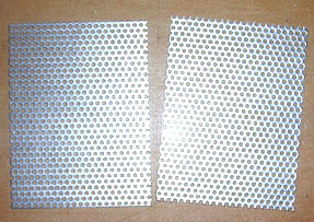 Your local steel supplier probably has some types on hand and can let you see how flexible a particular variety is. The shape shown above is for a "three plate per cell" design where there are two active plate faces. Ideally, you want two to four square inches of plate area per amp of current flowing through the cell, because that gives very long electrode life and minimum heating due to the plates. This style of construction is reasonably easy to assemble as the two bolts which pass through the partitions and which hold the plates rigidly in place, can be accessed from above, two spanners being used to lock them tight. Lock nuts are optional. If you feel that your particular mesh might be a little too flexible or if you think that the bolts might eventually loosen, then you can attach two, or more, separator insulating pieces - plastic washers, plastic bolts, cable ties or whatever to one of the plate faces. These will hold the plates apart even if they were to become loose. They also help to maintain the gap between the plates. This gap has to be a compromise because the closer the plates are together, the better the gas production but the more difficult it is for the bubbles to break away from the plates and float to the surface and if they don't do that, then they block off some of the plate area and prevent further gas production from that part of the plate as the electrolyte no longer touches the plate there. A popular choice of gap is 1/8 inch which is 3 mm as that is a good compromise spacing. Circular spacers would look like this:  If the current is low enough, an even more simple shape which has just a single pair of active plate surfaces per cell, can be used as shown here:  Any of these designs can be 6-cell or 7-cell and the plates can be constructed without outside help. You will notice that the electrical connections at each end of the booster are submerged to make sure that a loose connection can't cause a spark and ignite the hydroxy gas in the top of the housing. There should be a gasket washer on the inside to prevent any leakage of the electrolyte past the clamping bolt. If you want to use three active plate pairs in each cell, then the plate shape could be like this:  The electrolyte is a mix of water and an additive to allows more current to flow through the liquid. Most of the substances which people think of to use to make an electrolyte are most unsuitable, producing dangerous gasses, damaging the surfaces of the plates and giving uneven electrolysis and currents which are difficult to control. These include salt, battery acid and baking soda and I strongly recommend that you do not use any of these. What is needed is a substance which does not get used up during electrolysis and which does not damage the plates even after years of use. There are two very suitable substances for this: sodium hydroxide, also called "lye" or "caustic soda". In the USA, this is available in Lowes stores, being sold as "Roebic ‘Heavy Duty’ Crystal Drain Opener". The chemical formula for it is NaOH. One other substance which is even better is potassium hydroxide or "caustic potash" (chemical formula KOH) which can be got from soap-making supply shops found on the web. Both NaOH and KOH are very caustic materials and they need to be handled with considerable care. Bob Boyce of the USA is one of the most experienced people in the construction and use of boosters of different designs. He has kindly shared the following information on how to stay safe when mixing and using these chemicals. He says: These materials are highly caustic and so they need to be handled carefully and kept away from contact with skin, and even more importantly, eyes. If any splashes come in contact with you, it is very important indeed that the affected area be rinsed off immediately with large amounts of running water and if necessary, the use of vinegar which is acidic and so will neutralise the caustic liquid. When making up a solution, you add small amounts of the hydroxide to distilled water held in a container. The container must not be glass as most glass is not high enough quality to be a suitable material in which to mix the electrolyte. The hydroxide itself should always be stored in a sturdy, air-tight container which is clearly labelled "DANGER! - Potassium (or Sodium) Hydroxide". Keep the container in a safe place, where it can’t be reached by children, pets or people who won't take any notice of the label. If your supply of hydroxide is delivered in a strong plastic bag, then once you open the bag, you should transfer all of its contents to sturdy, air-tight, plastic storage containers, which you can open and close without any risk of spilling the contents. Hardware stores sell large plastic buckets with air tight lids that can be used for this purpose. When working with dry hydroxide flakes or granules, wear safety goggles, rubber gloves, a long sleeved shirt, socks and long trousers. Also, don’t wear your favourite clothes when handling hydroxide solution as it is not the best thing to get on clothes. It is also no harm to wear a face mask which covers your mouth and nose. If you are mixing solid hydroxide with water, always add the hydroxide to the water, and not the other way round, and use a plastic container for the mixing, preferably one which has twice the capacity of the finished mixture. The mixing should be done in a well-ventilated area which is not draughty as air currents can blow the dry hydroxide around. When mixing the electrolyte, never use warm water. The water should be cool because the chemical reaction between the water and the hydroxide generates a good deal of heat. If possible, place the mixing container in a larger container filled with cold water, as that will help to keep the temperature down, and if your mixture should “boil over” it will contain the spillage. Add only a small amount of hydroxide at a time, stirring continuously, and if you stop stirring for any reason, put the lids back on all containers. If, in spite of all precautions, you get some hydroxide solution on your skin, wash it off with plenty of cold running water and apply some vinegar to the skin. Vinegar is acidic, and will help balance out the alkalinity of the hydroxide. You can use lemon juice if you don't have vinegar to hand - but it is always a good idea to have a bottle of vinegar handy. The concentration of the electrolyte is a very important factor. Generally speaking, the more concentrated the electrolyte, the greater the current and the larger the volume of hydroxy gas produced. However, there are three major factors to consider: 1. The resistance to current flow through the metal electrode plates. 2. The resistance to current flow between the metal plates and the electrolyte. 3. The resistance to current flow through the electrolyte itself. 1. In a good electrolyser design like those shown above, the design itself is about as good as a DC booster can get, but understanding each of these areas of power loss is important for the best possible performance. We were taught in school that metals conduct electricity, but what was probably not mentioned was the fact that some metals such as stainless steel are quite poor conductors of electricity and that is why electrical cables are made with copper wires and not steel wires. This is how the current flow occurs with our electrolyser plates:  The fact that we have folds and bends in our plates has no significant effect on the current flow. Resistance to current flow through the metal electrode plates is something which can’t be overcome easily and economically, and so has to be accepted as an overhead. Generally speaking, the heating from this source is low and not a matter of major concern, but we provide a large amount of plate area to reduce this component of power loss as much as is practical. 2. Resistance to flow between the electrode and the electrolyte is an entirely different matter, and major improvements can be made in this area. After extensive testing, Bob Boyce discovered that a very considerable improvement can be made if a catalytic layer is developed on the active plate surface. Details of how this can be done are given later in the companion document "D9.pdf" as part of the description of Bob’s electrolyser.  3. Resistance to flow through the electrolyte itself can be minimised by using the best catalyst at its optimum concentration. When using sodium hydroxide, the optimum concentration is 20% by weight. As 1 cc of water weighs one gram, one litre of water weighs one kilogram. But, if 20% (200 grams) of this kilogram is to be made up of sodium hydroxide, then the remaining water can only weigh 800 grams and so will be only 800 cc in volume. So, to make up a 20% "by weight" mix of sodium hydroxide and distilled water, the 200 grams of sodium hydroxide are added (very slowly and carefully, as explained above by Bob) to just 800 cc of cool distilled water and the volume of electrolyte produced will be about 800 cc. When potassium hydroxide is being used, the optimum concentration is 28% by weight and so, 280 grams of potassium hydroxide are added (very slowly and carefully, as explained above by Bob) to just 720 cc of cold distilled water. Both of these electrolytes have a freezing point well below that of water and this can be a very useful feature for people who live in places which have very cold winters. Another factor which affects current flow through the electrolyte is the distance which the current has to flow through the electrolyte - the greater the distance, the greater the resistance. Reducing the gap between the plates to a minimum improves the efficiency. However, practical factors come into play here as bubbles need sufficient space to escape between the plates, and a good working compromise is a spacing of 3 mm. which is one eighth of an inch.  However, there is a problem with using the optimum concentration of electrolyte and that is the current flow caused by the greatly improved electrolyte is likely to be far more than we want. To deal with this we can use an electronic circuit called a "Pulse-Width Modulator" (or “PWM”) circuit. These are often sold as "DC Motor Speed Controllers" and if you buy one, then pick one which can handle 30 amps of current. A PWM circuit operates in a very simple way. It switches the current to the electrolyser On and Off many times every second. The current is controlled by how long (in any one second) the current is On, compared to how long it is Off. For example, if the On time is twice as long as the Off time (66%), then the average current flow will be much greater than if the On time were only half as long as the Off time(33%). When using a PWM controller, it is normal to place its control knob on or near the dashboard and to mount a simple low-cost ammeter beside it so that the driver can raise or lower the current flow as is considered necessary. The arrangement is like this:  There is a more sophisticated circuit controller called a "Constant-current Circuit" and that allows you to select the current you want and the circuit then holds the current at your set value at all times. However, this type of circuit is not readily available for sale although some outlets are preparing to offer them. Some of the most simple boosters don't use a PWM circuit because they control the current flow through the booster by making the concentration of the electrolyte very low so that the resistance to current flow through the electrolyte chokes off the current and holds it down to the desired level. This, of course, is far less efficient and the resistance in the electrolyte causes heating, which in turn, is an operational problem which needs careful handling by the user. The advantage is that the system appears to be more simple. Feeding the hydroxy gas to the engine. When using a booster of any design you need to realise that hydroxy gas is highly explosive. If it wasn’t, it would not be able to do it’s job of improving the explosions inside your engine. Hydroxy gas needs to be treated with respect and caution. It is important to make sure that it goes into the engine and nowhere else. It is also important that it gets ignited inside the engine and nowhere else. To make these things happen, a number of common-sense steps need to be taken. Firstly, the booster must not make hydroxy gas when the engine is not running. The best way to arrange this is to switch off the current going to the booster when the engine is not running. It is not sufficient to just have a manually-operated On/Off switch as it is almost certain that switching off will be forgotten one day. Instead, the electrical supply to the booster is routed through the ignition switch of the vehicle. That way, when the engine is turned off and the ignition key removed, it is certain that the booster is turned off as well. So as not to put too much current load on the ignition switch, and to allow for the possibility of the ignition switch being on when the engine is not running, instead of wiring the booster directly to the switch, it is better to wire a standard automotive relay across the oil pressure unit and let the relay carry the booster current. The oil pressure drops when the engine stops running, and so this will also power down the booster. An extra safety feature is to allow for the (very unlikely) possibility of an electrical short-circuit occurring in the booster or its wiring. This is done by putting a fuse or contact-breaker between the battery and the new circuitry as shown in this diagram:  If you choose to use a contact-breaker, then a light-emitting diode (“LED”) with a current limiting resistor of say, 680 ohms in series with it, can be wired directly across the contacts of the circuit breaker. The LED can be mounted on the dashboard. As the contacts are normally closed, they short-circuit the LED and so no light shows. If the circuit-breaker is tripped, then the LED will light up to show that the circuit-breaker has operated. The current through the LED is so low that the electrolyser is effectively switched off when the contact breaker opens. This is not a necessary feature, merely an optional extra:  A good source for general components needed in building boosters is The Hydrogen Garage in the USA, website. A very important safety item for any booster is the “bubbler” which is just a simple container with some water in it. The bubbler has the gas coming in at the bottom and bubbling up through the water. The gas collects above the water surface and is then drawn into the engine through an outlet pipe above the water surface. To prevent water being drawn into the booster when the booster is off for any length of time and the pressure inside it reduces, a one-way valve is placed in the pipe between the booster and the bubbler. If the engine happens to backfire, then the bubbler blocks the flame from passing back through the pipe and igniting the gas being produced in the booster. A bubbler is a very simple, very cheap and very sensible thing to install. It also removes any traces of electrolyte fumes from the gas before it is drawn into the engine. In practice, it is a very good idea to have two bubblers, one close to the booster and one close to the engine. The second bubbler makes sure that every last trace of electrolyte fumes are washed out of the hydroxy gas before it enters the engine. There are various ways to make a good bubbler. In general, you are aimed at having a five-inch (125 mm) depth of water through which the hydroxy gas must pass before it leaves the bubbler. It is recommended that a bubbler is built inside a strong container such as this one: 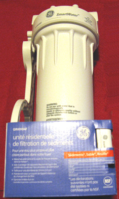 These strong containers are generally sold as water filters. They can be adapted to become bubblers without any major work being done on them. At this point, we need to consider the mechanism for moving the hydroxy gas out of the booster and into the engine. It is generally a good idea to position the gas take-off pipe in the centre of the lid so that if the booster gets tilted due to the vehicle operating on a sloped surface, then the surface level of the liquid remains unchanged underneath the gas pipe. A common mistake is to use a gas pipe which has a small diameter. If you take a length of plastic pipe of a quarter inch diameter (6 mm) and try blowing through it, you will be surprised at how difficult it is to blow through. There is no need to give your booster that problem, so I suggest that you select a gas pipe of half an inch (12 mm) or so. If in doubt as to how suitable a pipe is, then try blowing through a sample length of it. If you can blow through it without the slightest difficulty, then it is good enough for your booster. One other thing is how to deal with splashes and the spray from bubbles bursting at the surface of the electrolyte. You want some device which will prevent any spray or splashes caused by the vehicle going over a very rough road, from entering the gas pipe and being drawn out of the booster along with the hydroxy gas. Various methods have been used and it is very much a matter of personal choice as to how you decide to deal with the issue. One method is to use a piece of suitable material across the end of the pipe. This is generally called anti-slosh material because of the job which it does. The material needs to let the gas pass freely through it but prevent any liquid getting through it. Plastic pot-scrubbers as a possible material as they have an interlocking mesh of small flat strands. The gas can flow around and through the many strands, but splashes which go in a straight line will hit the strands and drip back into the booster again. Another possible device is one or more baffles which will catch the liquid but let the gas pass freely by: 
OR 
OR  The hydroxy gas produced by a DC booster of this type contains about 30% monatomic hydrogen, which means that 30% of the hydrogen is in the form of single atoms of hydrogen and not combined hydrogen pairs of atoms. The monatomic form is about four times more energetic than the combined form and so it takes up a greater volume inside the booster housing. If the booster is left turned off for a long period of time, then these single hydrogen atoms will eventually bump into each other and combine to form the less energetic diatomic form of the gas. As this takes up less space inside the booster, the pressure inside the booster drops and this has been known to suck water out of the bubbler back into the booster. We don't want this to happen as it dilutes our carefully measured electrolyte concentration and it can make the bubbler ineffective due to lack of water. To deal with this, a one-way valve is put between the booster and the bubbler, positioned so that it does not allow flow back into the booster. In very cold climates, a 28% by weight potassium hydroxide electrolyte will not freeze until -40o C, it is more difficult to stop the bubblers freezing. While it is possible to have equipment which unplugs and can be taken indoors overnight, an alternative is to use alcohol or paraffin (kerosene) instead of water and they generally do not freeze and their fumes are not harmful to an engine.  The bubbler design is not difficult. Ideally, you want a very large number of small bubbles to be formed and float upwards through the water. This is because it gives the best connection between the gas and the water and so can do a really good job of washing any traces of hydroxide vapour out of the hydroxy gas before it gets fed to the engine. Small bubbles are also better separated from each other and so there is no real chance of a flame passing through the water where large bubbles might merge together and form a column of gas as they rise to the surface.  In this good bubbler design, the pipe which feeds the hydroxy gas into the bubbler is bent into an L-shape. The end of the pipe is blocked off, and many small holes are drilled in the horizontal section of the pipe. Only a few holes are seen in this diagram, but there will be a large number in the actual construction. Like the booster itself, the gas outlet pipe needs to be protected from splashes of water caused by the vehicle going over a bump. It is very important to make sure that water is not drawn into the engine along with the gas, so anti-slosh material or one or more baffles are used to prevent this happening. So the overall protection for the gas flow is:  Where the first bubbler is close to the booster and the second one is placed close to the engine. Once in a while, the water from the first bubbler can be used to top up the water inside the booster so that any traces of hydroxide which may have reached the bubbler are returned to the booster, keeping its electrolyte concentration exactly right and making sure that the water in the bubbler is always fresh. There is one final item which is an optional extra. Some people like to add a gas-pressure switch. If, for any reason, the pressure starts to rise - say that the outlet pipe became blocked - then the pressure switch would disconnect the electrical supply and stop the pressure rising any further: 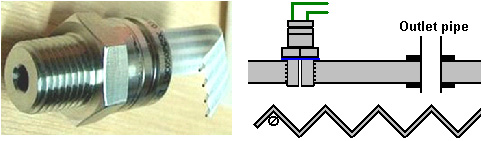 One decision which has to be made is the rate of hydroxy gas production which is the best for you. Most people seem to think that the larger the volume of hydroxy gas the better. That is not necessarily true because a very effective use of the gas is to make it act as an igniter for the engine's normal fuel and very satisfactory results have been achieved with hydroxy gas flow rates in the range of 0.4 to 0.7 litres per minute. You control the rate of gas production by controlling the current, either by the concentration of the electrolyte or by adjusting the current flow using an electronic circuit. Each litre of water produces about 1,750 litres of hydroxy gas, so you can estimate the length of time the booster can operate on one litre of water. If, for example, your booster is producing 0.7 litres of gas per minute. Then, it will produce 1,750 litres in 1,750 / 0.7 minutes and that is 2,500 minutes or 41 hours 40 minutes. As the booster only operates when you are driving, you are looking at 41 hours of driving time and if you drive about two hours per day, it would take three weeks to use one litre of water. The internal dimensions of your booster allow you to calculate how far the electrolyte level will drop if one litre of water is taken out of it. Generally speaking, it is normally considered that topping up the booster with water by hand every so often, is a perfectly good method of operation. The booster design described above has a good electrolyte capacity in each cell and so topping up with water should not be a major task. As tap water and well water have a good deal of dissolved solids in them, when the water is taken away by electrolysis, these solids drop out of solution and fall to the bottom of the housing, and/or coat the plates with an layer of unwanted material. For this reason, life is so much easier if distilled water is used for making electrolyte and for topping up the booster after use. It is possible to have an automatic water supply for your booster even though that is probably over-kill for such a simple device. If you decide to do that, then you need a water supply nozzle for each of your six or seven cells. It is not necessary for the electrolyte level to be exactly the same in each cell, but you would normally have them at roughly the same height. Your automated water supply could be like this:    A point which might not be immediately obvious is that because the gas pressure inside the booster is probably about 5 pounds per square inch ("psi"), once the water pump stops pumping, it is possible for the gas pressure to push out the remaining water in the inlet pipes and escape through the body of the pump. To prevent this, an ordinary one-way valve is put in the water supply pipe to prevent flow back towards the pump. Up to now, the hydroxy gas feed to the engine has just been indicated in a vague way in spite of the connection point being important. With most engines, the hydroxy gas should be fed into the air filter where it mixes well and is fully dispersed inside the air being drawn into the engine. You sometimes see diagrams which show the connection point being close to the engine intake manifold. This is not a good idea because the lowered pressure there causes reduced pressure inside the booster which in turn produces more unwanted hot water vapour, so stick with feeding the gas into the air filter. If there is a supercharger on the engine, then feed the hydroxy gas into the low-pressure side of the supercharger. The style of booster described above has the advantages of high electrical efficiency, easy construction, very few specialist parts and a large electrolyte volume per cell. There are many other very successful booster designs which have very different forms of construction. One of these is the "Smack's Booster" where electrical cover plates are clamped together and placed inside a length of plastic pipe: 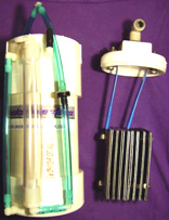 The advantages of this design are the very simple construction, compact size, reasonable performance and the fact that you can buy one ready-made if you want to. The website with full details and advice for this design is here or you can download a copy of the construction details free from here The electrical efficiency of this design is lowered a bit because only a single body of electrolyte is used and so current can bypass the plates. The overall performance is a respectable 1.3 lpm for 20 amps, though you may wish to lower the current and settle for about half that rate of hydroxy gas production. Another design which is very easy to build is the "HotSabi" booster, which is a single threaded rod inside a length of plastic pipe with a stainless steel inner lining. It has the lowest possible electrical efficiency, being just a single cell with the full vehicle voltage connected directly across it, but in spite of that, it's performance in actual on the road use has been remarkable, with a reported 50% improvement on a 5 litre capacity engine. This excellent performance is probably due to the design having a steam trap which removes the hot water vapour produced by the excessive heating caused by having only a single cell with so much voltage across it (remember, 90% of the power supplied to this booster design goes in heating the electrolyte). 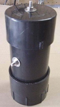  As the designer of this booster has freely shared his design, the free construction plans can be downloaded from here Another, very different booster design comes from Zach West who uses stainless steel shimstock for the electrodes, rather than flat plates. He coils the electrodes round and round in a spiral and inserts each pair into a separate, small-diameter plastic pipe, to make one cell. These separate cells can then be connected in various ways, and the gas output can be very high:  The construction details for this, rather more complicated design, can be downloaded free from here A fully-submerged design from Bill Williams in the USA is another different style of booster:  The construction details for this booster design, can be downloaded free from here There are many other designs, including those with concentric pipes, each having its own advantages and disadvantages, some being commercially available as ready-made devices, and there are links to these boosters on the web sites mentioned above and a general booster forum and another here where people will answer any queries. One problem with the use of boosters is that if the hydroxy gas volume is higher than it needs to be, the vehicle's Electronic Control Unit ("ECU") is liable to detect the improved fuel burn and start pumping in excess fuel to offset the improved conditions. How to deal with this situation is covered in the free document which can be downloaded from here 2. Advanced DC Boosters All of the practical construction details on electrical safety, gas safety, engine connections, type of water, safe mixing of electrolyte, etc. already discussed, apply to all kinds of electrolysers and boosters of every design. So, please understand that these are universal features which need to be understood when using any design of booster. It is possible to produce large volumes of hydroxy gas from a DC booster, enough gas to run a small motor directly on it. For this, we need to pay attention to the efficiency factors already covered in this document. The person who is outstanding in this field is Bob Boyce of the USA who has kindly shared his experience and expertise freely with people who want to use serious electrolysers. Bob's attention to detail when constructing high-performance electrolysers has resulted in efficiencies which are more than double those of the very famous Michael Faraday whom most scientists consider to be the final word on electrolysis. We are now moving from the "casual" style of booster to the "serious" style of electrolyser. In this category, you will find that the units built are not cheap, weight a considerable amount, require considerable skill to make and usually are quite large physically. I will mention two designs here. First, the very well-known design from Bob Boyce. For this electrolyser, Bob makes solid stainless steel electrode plates act as cell partitions as well as being electrodes. This is a clever technique but it takes a very high level of construction accuracy to make a box with slots in the side and base, so that the stainless steel plates can be slid into the box and when there, form a watertight seal between the cells, preventing electrical current bypassing the places by flowing around them. The number of cells in the electrolyser depends on the electrical DC voltage supply which is produced from the electrics of the vehicle. This higher voltage is created by using a standard off-the-shelf "inverter" which produces high-voltage alternating current ("AC") meant to be the equivalent of the local electricity mains supply. In the USA, the voltage produced is in the 110 to 120 volt region, elsewhere, it is in the 220 to 230 volt region. If you are not familiar with electrical jargon, then check out chapter 12 which explains it step by step. The AC output from whatever inverter you buy, is changed back into DC by using a component called a "diode bridge" and a reservoir device called a capacitor. When this is done, the resulting DC voltage is 41% greater than the quoted AC voltage, so a 110-volt inverter will produce about 155 volts and a 220-volt inverter about 310 volts. As you want about 2 volts per cell, the number of cells would be about 80 or 150 depending on which inverter is used. This large number of stainless steel plates each sized at six-inches (100 mm) square, creates a substantial weight which then is increased by the weight of the case, and the electrolyte. The overall arrangement (without the capacitor) is like this:  A very high-precision box for this style of electrolyser can be had from Ed Holdgate of Florida who has also shared the construction methods if you fancy yourself as a skilled fabricator: 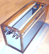 Ed's website is here and each case is hand-made. The gas production rate is so high that the gas outlet pipe has to have holes drilled along the top in order to try to exclude spray and moisture from the massive rate of bubbles bursting at the surface of the electrolyte. The high efficiency of Bob's electrolysers is due to his meticulous preparation and construction methods. You will notice that Bob recommends the use of a particle filter with a 1-micron mesh, between the engine and the hydroxy system. Apart from ensuring that everything entering the engine is very clean, the particle filter with a mesh of that small size, also acts as a flashback-preventer as flame can't pass through it. Firstly, the stainless steel plates are cross-scored with sandpaper to create a specially shaped plate surface which helps high-speed bubble release. Secondly, the plates are put through a rigorous "cleansing" process where they are subjected to repeated periods of electrolysis followed by rinsing particles off the plates and filtering the electrolyte solution. When no further particles break free from the plates, they are then put through a "conditioning" process which develops a catalytic layer on the plate surfaces. This processing and the various construction details are provided in the following free download document, thanks to Bob's generosity in sharing his experience with us here and there is a forum for Bob's design here where questions are answered. 3. Pulsed Water-splitters There is a much more efficient way of converting water into a hydroxy gas mix. Unlike the electrolysis devices already described, this method does not need an electrolyte. Pioneered by Stanley Meyer, pulse trains are used to stress water molecules until they break apart, forming the required gas mix. Henry Puharich also developed a very successful system with a somewhat different design. Neither of these gentlemen shared sufficient practical information for us to replicate their designs as a routine process, so we are in a position today where we are searching for the exact details of the methods which they used. The first significant replication of which I am aware, came from Dave Lawton of Wales. By using very considerable tenacity, he discovered the practical details of how to replicate one of Stan Meyer's early designs which is called by the rather confusing name of the "Water Fuel Cell". Dave's work was copied and experimented with by Ravi Raju of India who had considerable success and who posted videos of his results on the web. More recently, Dr Scott Cramton of the USA has adapted the design construction slightly and achieved very satisfactory rates of electrical efficiency, producing some 6 lpm of hydroxy gas for just 3 amps of current at 12 volts.  The video of Dave Lawton’s replication of Stanley Meyer’s demonstration electrolyser (not Stan's production system) seen here has caused several people to ask for more details. The electrolysis shown in that video was driven by an alternator, solely because Dave wanted to try each thing that Stan Meyer had done. Dave’s alternator and the motor used to drive it are shown here: 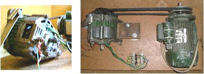 The technique of DC pulsing requires the use of electronics, so the following descriptions contain a considerable amount of circuitry. If you are not already familiar with such circuits, then you would be well advised to read through Chapter 12 which explains this type of circuitry from scratch. The field coil of Dave's alternator is switched on and off by a Field-Effect Transistor (a “FET”) which is pulsed by a dual 555 timer circuit. This produces a composite waveform which produces an impressive rate of electrolysis. The tubes in this replication are made of 316L grade stainless steel, five inches long although Stan’s tubes were about sixteen inches long. The outer tubes are 1 inch in diameter and the inner tubes 3/4 inch in diameter. As the wall thickness is 1/16 inch, the gap between them is between 1 mm and 2 mm. The inner pipes are held in place at each end by four rubber strips about one quarter of an inch long. The container is made from two standard 4 inch diameter plastic drain down-pipe coupler fittings connected to each end of a piece of acrylic tube with PVC solvent cement. The acrylic tube was supplied already cut to size by Wake Plastics, 59 Twickenham Road, Isleworth, Middlesex TW7 6AR Telephone 0208-560-0928. The seamless stainless steel tubing was supplied by http://www.metalsontheweb.co.uk/asp/home.asp It is not necessary to use an alternator - Dave just did this as he was copying each thing that Stan Meyer did. The circuit without the alternator produces gas at about the same rate and obviously draws less current as there is no drive motor to be powered. A video of the non-alternator operation can be downloaded here. Dave's electrolyser has an acrylic tube section to allow the electrolysis to be watched, as shown here: 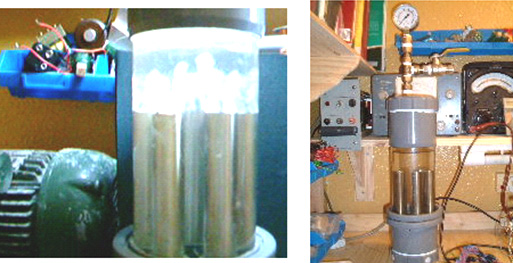 The electrolysis takes place between each of the inner and outer tubes. The picture above shows the bubbles just starting to leave the tubes after the power is switched on. The picture below shows the situation a few seconds later when the whole of the area above the tubes is so full of bubbles that it becomes completely opaque: 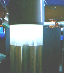 The mounting rings for the tubes can be made from any suitable plastic, such as that used for ordinary food-chopping boards, and are shaped like this: 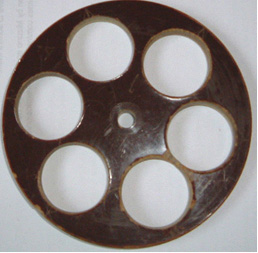 And the 316L grade stainless steel, seamless tubes are held like this: 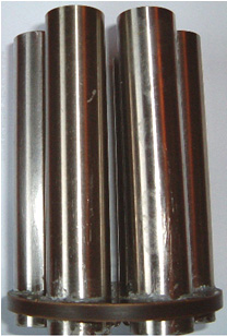 Here is the assembly ready to receive the inner tubes (wedged into place by small pieces of rubber): 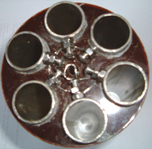 The electrical connections to the pipes are via stainless steel wire running between stainless steel bolts tapped into the pipes and stainless steel bolts running through the base of the unit:  The bolts tapped into the inner tubes should be on the inside. The bolts going through the base of the unit should be tapped in to give a tight fit and they should be sealed with Sikaflex 291 or marine GOOP bedding agent which should be allowed to cure completely before the unit is filled for use. An improvement in performance is produced if the non-active surfaces of the pipes are insulated with any suitable material. That is, the outsides of the outer tubes and the insides of the inner tubes, and if possible, the cut ends of the pipes. While Dave’s style of construction is simple and straightforward, recently, a copy of one of Stan Meyer’s actual construction drawings has surfaced. The image quality of this copy is so low that much of the text can’t be read, so the replication presented here may not be exact or might be missing some useful item of information. Stan’s construction is unusual. First, a piece of plastic is shaped as shown here:  The size of this disc is matched exactly to the piece of clear acrylic used for the body of the housing. The drawing does not make it clear how this disc is attached to the acrylic tube, whether it is a tight push fit, glued in place or held in position with bolts which are not shown. The implication is that a ring of six bolts are driven through the top and tapped into the acrylic tube, as these are shown on one of the plan views, though not on the cross-section. It would also be reasonable to assume that a similar ring of six bolts is also used to hold the base securely in position. There is a groove cut in the plastic base to take an O-ring seal which will be compressed tightly when the disc is in place. There are either two or three threaded stud recesses plus two through holes to carry the electric current connections. The pipe support arrangement is unusual:  A ring of nine evenly-spaced inner pipes are positioned around the edge of a steel disc which is slightly smaller than the inside dimension of the acrylic tube. The pipes appear to be a tight push-fit in holes drilled very accurately through the disc. These holes need to be exactly at right-angles to the face of the disc in order for the pipes to be exactly aligned with the acrylic tube – definitely a drill-press job. The disc is mounted on a central threaded rod which projects through the plastic base disc, and a plastic spacer is used to hold the disc clear of the studs positioned at ninety degrees apart around the outer edge of the base disc. The mounting for the outer tubes is also most unusual. A piece of steel plate is cut with nine projecting arms at evenly-spaced positions around a circular washer shape as shown here:  This piece has four holes drilled in it to match the stud positions of the plastic base piece. The number of studs is not specified and while I have shown four, the plate resonance might be helped if there were just three. The size is arranged so that when the arms are bent upwards at right-angles, they fit exactly against the inner face of the acrylic tube. These arms get two bends in them in order to kink them inwards to form mounts for the outer tubes. The degree of accuracy needed her is considerable as it appears that there are no spacers used between the inner and outer tubes. This means that the very small gap of 1.5 mm or so has to be maintained by the accuracy of these mounts for the outer tubes. It should be noted that the inner tubes are much longer than the outer tubes and that the outer tubes have a tuning slot cut in them. All of the inner tubes are mechanically connected together through their steel mounting disc and all of the outer tubes are connected together through the ring-shaped steel disc and its kinked arm mounts. It is intended that both of these assemblies should resonate at the same frequency, and they are tuned to do just that. Because the inner tubes have a smaller diameter, they will resonate at a higher frequency than a larger diameter pipe of the same length. For that reason, they are made longer to lower their natural resonant frequency. In addition to that, the slots cut in the outer tubes are a tuning method which raises their resonant pitch. These slots will be adjusted until every pipe resonates at the same frequency. Looking initially at the mechanical design, suggests that the assembly is impossible to assemble, and while that is almost true, as it will have to be constructed as it is assembled and it appears that the inner and outer pipe assembly can’t be taken apart after assembly. This is the way they are put together:  The ring support for the outer pipes is not bolted securely to the plastic base but instead it is spaced slightly above it and mounted on just the stud points. This ring is underneath the slightly smaller diameter disc which holds the inner pipes. This makes it impossible for the two components to be slid together or apart, due to the length of the pipes. This suggests that either the inner pipes are pushed into place after assembly (which is highly unlikely as they will have been assembled before for tuning) or that the outer pipes are welded to their supports during the assembly process (which is much more likely). One of the “studs” is carried right through the plastic base in order that it can become the positive connection of the electrical supply, fed to the outer pipes. The central threaded rod is also carried all the way through the plastic base and is used to support the steel plate holding the inner pipes as well as providing the negative electrical connection, often referred to as the electrical “ground”. Another plastic disc is machined to form a conical lid for the acrylic tube, having a groove to hold an O-ring seal and the water inlet for refilling and the gas output tube. The drawing mentions the fact that if tap water is used, then the impurities in it will collect in the bottom of the electrolyser when the water is removed by being converted to hydroxy gas. This means that the cell would have to be rinsed out from time to time. It also draws attention to the fact that the gasses dissolved in the tap water will also come out during use and will be mixed with the hydroxy gas output. When these various components are put together, the overall cell construction is shown like this:  This cross-sectional view may be slightly misleading as it suggests that each of the nine outer pipes has its own separate bracket and this is probably not the case as they are connected together electrically through the steel ring-shaped disc and should vibrate as a single unit. It is tempting to use separate brackets as that would allow the assembly to be taken apart quite easily, but the electrical contacts of such a system would be much inferior and so it is not to be recommended. Because of the way that all of the inner pipes are connected together and all of the outer pipes are connected together electrically, this form of construction is not suited to the three-phase alternator drive shown below, where the nine pipes would have to be connected in separate sets of three. Instead, the solid-state circuit is used, which is very effective and which does not have the size, weight, noise and increased current of the alternator arrangement. If accuracy of construction is a problem, then it might be possible to give the outer pipes a deliberate slope so that they press against the inner pipes at the top, and then use one short spacer to force them apart and give the desired spacing. It seems clear that Stan worked to such a degree of constructional accuracy that his pipes were perfectly aligned all along their lengths. Dave Lawton points out that the connection point of the brackets for the outer pipes is highly critical as they need to be at a resonating node of the pipes. The connection point is therefore at 22.4% of the length of the pipe from the bottom of the pipe. Presumably, if a slot is cut in the top of the pipe, then the resonant pipe length will be measured to the bottom of the slot and the connection point set at 22.4% of that length. Dave Lawton’s pipe arrangement can be driven either via an alternator or by an electronic circuit. A suitable circuit for the alternator arrangement is:  In this rather unusual circuit, the rotor winding of an alternator is pulsed via an oscillator circuit which has variable frequency and variable Mark/Space ratio and which can be gated on and off to produce the output waveform shown below the alternator in the circuit diagram. The oscillator circuit has a degree of supply de-coupling by the 100 ohm resistor feeding the 100 microfarad capacitor. This is to reduce voltage ripple coming along the +12 volt supply line, caused by the current pulses through the rotor winding. The output arrangement feeding the pipe electrodes of the electrolyser is copied directly from Stan Meyer’s circuit diagram. It is not recommended that you use an alternator should you decide to build a copy of your own. But if you decide to use one and the alternator does not have the windings taken to the outside of the casing, it is necessary to open the alternator, remove the internal regulator and diodes and pull out three leads from the ends of the stator windings. If you have an alternator which has the windings already accessible from the outside, then the stator winding connections are likely to be as shown here:  The motor driving Dave’s alternator draws about two amps of current which roughly doubles the power input to the circuit. There is no need for the size, weight, noise, mechanical wear and current draw of using a motor and alternator as pretty much the same performance can be produced by the solid-state circuit with no moving parts. Both circuits have been assessed as operating at anything from 300% to 900% of Faraday’s “maximum electrical efficiency”, it should be stressed that the inductors used in this circuit, form a very important role in altering and amplifying the voltage waveform applied to the cell. Dave uses two “bi-filar wound” inductors, each wound with 100 turns of 22 SWG (21 AWG) enamelled copper wire on a 9 mm (3/8”) diameter ferrite rod. The length of the ferrite rod is not at all critical, and a ferrite toroid could be used as an alternative, though that is more difficult to wind. These bi-filar coils are wound at the same time using two lengths of wire side by side. The solid-state circuit is shown here:  Circuit operation: The main part of the circuit is made up of two standard 555 chip timers. These are wired to give an output waveform which switches very rapidly between a high voltage and a low voltage. The ideal waveform shape coming from this circuit is described as a “square wave” output. In this particular version of the circuit, the rate at which the circuit flips between high and low voltage (called the “frequency”) can be adjusted by the user turning a knob. Also, the length of the ON time to the OFF time (called the “Mark/Space Ratio”) is also adjustable. This is the section of the circuit which does this:  The 100 ohm resistor and the 100 microfarad capacitor are there to iron out any ripples in the voltage supply to the circuit, caused by fierce pulses in the power drive to the electrolysis cell. The capacitor acts as a reservoir of electricity and the resistor prevents that reservoir being suddenly drained if the power supply line is suddenly, and very briefly, pulled down to a low voltage. Between them, they keep the voltage at point “A” at a steady level, allowing the 555 chip to operate smoothly. The very small capacitor “B” is wired up physically very close to the chip. It is there to short-circuit any stray, very short, very sharp voltage pulses picked up by the wiring to the chip. It is there to help the chip to operate exactly as it is designed to do, and is not really a functional part of the circuit. So, for understanding how the circuit works, we can ignore them and see the circuit like this:  This circuit generates output pulses of the type shown in green with the voltage going high, (the “Mark”) and low (the “Space”). The 47K variable resistor (which some people insist on calling a “pot”) allows the length of the Mark and the Space to be adjusted from the 50 - 50 shown, to say, 90 - 10 or any ratio through to 10 - 90. It should be mentioned that the “47K” is not at all critical and these are quite likely to be sold as “50K” devices. Most low cost components have a plus or minus 10% rating which means that a 50K resistor will be anything from 45K to 55K in actual value. The two “1N4148” diodes are there to make sure that when the Mark/Space 47K variable resistor is adjusted, that it does not alter the frequency of the output waveform in any way. The remaining two components: the 10K variable resistor and the 47 microfarad capacitor, both marked in blue, control the number of pulses produced per second. The larger the capacitor, the fewer the pulses per second. The lower the value of the variable resistor, the larger the number of pulses per second. The circuit can have additional frequency tuning ranges, if the capacitor value is altered by switching in a different capacitor. So the circuit can be made more versatile by the addition of one switch and, say, two alternative capacitors, as shown here:  The capacitors shown here are unusually large because this particular circuit is intended to run relatively slowly. In the almost identical section of the circuit which follows this one, the capacitors are very much smaller which causes the switching rate to be very much higher. Experience has shown that a few people have had overheating in this circuit when it is switched out of action, so the On/Off switch has been expanded to be a two-pole changeover switch and the second pole used to switch out the timing elements of the 555 chip. The complete version of this section of the circuit is then:  which just has one additional switch to allow the output to be stopped and the 12-volt supply line to be fed instead. The reason for this is that this part of the circuit is used to switch On and Off an identical circuit. This is called “gating” and is explained in Chapter 12 which is an electronics tutorial. The second part of the circuit is intended to run at much higher speeds, so it uses much smaller capacitors:  So, putting them together, and allowing the first circuit to switch the second one On and Off, we get:  The final section of the circuit is the power drive for the electrolyser cell. This is a very simple circuit. Firstly, the output of the second 555 chip is lowered by a basic voltage-divider pair of resistors, and fed to the Gate of the output transistor:  Here, the 555 chip output voltage is lowered by 220 / 820 or about 27%. When the voltage rises, it causes the BUZ350 transistor to switch on, short-circuiting between its Drain and Source connections and applying the whole of the 12-volt supply voltage across the load, which in our application, is the electrolyser cell:  The transistor drives the electrolysis electrodes as shown above, applying very sharp, very short pulses to them. What is very important are the wire coils which are placed on each side of the electrode set. These coils are linked magnetically because they are wound together on a high-frequency ferrite rod core and although a coil is such a simple thing, these coils have a profound effect on how the circuit operates. Firstly, they convert the 555 chip pulse into a very sharp, very short, high-voltage pulse which can be as high as 1,200 volts. This pulse affects the local environment, causing extra energy to flow into the circuit. The coils now perform a second role by blocking that additional energy from short-circuiting through the battery, and causing it to flow through the electrolysis cell, splitting the water into a mix of hydrogen and oxygen, both gases being high-energy, highly charged atomic versions of those gases. This gives the mix some 400% the power of hydrogen being burned in air. When the transistor switches off, the coils try to pull the transistor Drain connection down to a voltage well below the 0-volt battery line. To prevent this, a 1N4007 diode is connected across the cell and its coils. The diode is connected so that no current flows through it until the transistor Drain gets dragged down below the 0-volt line, but then that happens, the diode effectively gets turned over and as soon as 0.7 volts is placed across it, it starts to conduct heavily and collapses the negative voltage swing, protecting the transistor, and importantly, keeping the pulsed waveform restricted to positive DC pulses, which is essential for tapping this extra environmental energy which is what actually performs the electrolysis. You can easily tell that it is the environmental “cold” electricity which is doing the electrolysis as the cell stays cold even though it is putting out large volumes of gas. If the electrolysis were being done by conventional electricity, the cell temperature would rise during the electrolysis. A John Bedini pulser circuit can be used very effectively with a cell of this type and it adjusts automatically to the resonant frequency as the cell is part of the frequency-determining circuit. The BUZ350 MOSFET has a current rating of 22 amps so it will run cool in this application. However, it is worth mounting it on an aluminium plate which will act as both the mounting and a heat sink but it should be realised that this circuit is a bench-testing circuit with a maximum current output of about 2 amps and it is not a Pulse-Width Modulation circuit for a high-current DC electrolyser. The current draw in this arrangement is particularly interesting. With just one tube in place, the current draw is about one amp. When a second tube is added, the current increases by less than half an amp. When the third is added, the total current is under two amps. The fourth and fifth tubes add about 100 milliamps each and the sixth tube causes almost no increase in current at all. This suggests that the efficiency could be raised further by adding a large number of additional tubes, but this is actually not the case as the cell arrangement is important. Stan Meyer ran his VolksWagen car for four years on the output from four of these cells with 16-inch (400 mm) electrodes, and Stan would have made a single larger cell had that been feasible. Although the current is not particularly high, a five or six amp circuit-breaker, or fuse, should be placed between the power supply and the circuit, to protect against accidental short-circuits. If a unit like this is to be mounted in a vehicle, then it is essential that the power supply is arranged so that the electrolyser is disconnected if the engine is switched off. Passing the electrical power through a relay which is powered via the ignition switch is a good solution for this. It is also vital that at least one bubbler is placed between the electrolyser and the engine, to give some protection if the gas should get ignited by an engine malfunction.  Although printed circuit boards have now been produced for this circuit and ready-made units are available commercially, you can build your own using stripboard if you want to. A possible one-off prototype style component layout for is shown here:  The underside of the strip-board (when turned over horizontally) is shown here:    Although using a ferrite ring is probably the best possible option, the bi-filar coil can be wound on any straight ferrite rod of any diameter and length. You just tape the ends of two strands of wire to one end of the rod and then rotate the rod in your hands, guiding the strands into a neat side-by-side cylindrical winding as shown here:   Dave, who built this replication, suggests various improvements. Firstly, Stan Meyer used a larger number of tubes of greater length. Both of those two factors should increase the gas production considerably. Secondly, careful examination of video of Stan’s demonstrations shows that the outer tubes which he used had a rectangular slot cut in the top of each tube:  Some organ pipes are fine-tuned by cutting slots like this in the top of the pipe, to raise it’s pitch, which is it’s frequency of vibration. As they have a smaller diameter, the inner pipes in the Meyer cell will resonate at a higher frequency than the outer pipes. It therefore seems probable that the slots cut by Stan are to raise the resonant frequency of the larger pipes, to match the resonant frequency of the inner pipes. If you want to do that, hanging the inner tube up on a piece of thread and tapping it, will produce a sound at the resonant pitch of the pipe. Cutting a slot in one outer pipe, suspending it on a piece of thread and tapping it, will allow the pitch of the two pipes to be compared. When one outer pipe has been matched to your satisfaction, then a slot of exactly the same dimensions will bring the other outer pipes to the same resonant pitch. It has not been proved, but it has been suggested that only the part of the outer pipe which is below the slot, actually contributes to the resonant frequency of the pipe. That is the part marked as “H” in the diagram above. It is also suggested that the pipes will resonate at the same frequency if the area of the inside face of the outer pipe (“H” x the inner circumference) exactly matches the area of the outer surface of the inner pipe. It should be remembered that as all of the pipe pairs will be resonated with a single signal, that each pipe pair needs to resonate at the same frequency as all the other pipe pairs. It is said that Stan ran his VolksWagen car for four years, using just the gas from four of these units which had pipe pairs 16-inchs long. A very important part of the cell build is the conditioning of the electrode tubes, using tap water. Ravi in India suggests that this is done as follows: 1. Do not use any resistance on the negative side of the power supply when conditioning the pipes. 2. Start at 0.5 Amps on the signal generator and after 25 minutes, switch off for 30 minutes 3. Then apply 1.0 Amps for 20 minutes and then stop for 30 minutes. 4. Then apply 1.5 Amps for 15 minutes and then stop for 20 minutes. 5. Then apply 2.0 Amps for 10 minutes and afterwards stop for 20 minutes. 6. Go to 2.5 Amps for 5 minutes and stop for 15 minutes. 7. Go to 3.0 Amps for 120 to 150 seconds. You need to check if the cell is getting hot...if it is you need to reduce the time. After the seven steps above, let the cell stand for at least an hour before you start all over again. You will see hardly any gas generation in the early stages of this conditioning process, but a lot of brown muck will be generated. Initially, change the water after every cycle, but do not touch the tubes with bare hands. If the ends of the tubes need to have muck cleaned off them, then use a brush but do not touch the electrodes!! If the brown muck is left in the water during the next cycle, it causes the water to heat up and you need to avoid this. Over a period of time, there is a reduction in the amount of the brown stuff produced and at some point, the pipes won’t make any brown stuff at all. You will be getting very good gas generation by now. A whitish powdery coat of chromium oxide dielectric will have developed on the surfaces of the electrodes. Never touch the pipes with bare hands once this helpful coating has developed. Important: Do the conditioning in a well-ventilated area, or alternatively, close the top of the cell and vent the gas out into the open. During this process, the cell is left on for quite some time, so even a very low rate of gas production can accumulate a serious amount of gas which would be a hazard if left to collect indoors. It has been suggested that if a BUZ350 can’t be obtained, then it would be advisable to protect the output FET against damage caused by accidental short-circuiting of wires, etc., by connecting what is effectively a 150-volt, 10 watt zener diode across it as shown here:  While this is not necessary for the correct operation of the circuit, it is helpful in cases where accidents occur during repeated testing and modification of the cell components. Dr Scott Cramton. Dr. Cramton and his team of Laesa Research and Development scientists have been investigating and advancing this technology and they have reached an output of six litres per minute for an electrical input of 12 watts (1 amp at 12 volts). In addition, Dr. Cramton’s cell has stable frequency operation and is being run on local well water. The objective is to reduce the amount of diesel fuel needed to run a large capacity standard electrical generator. The style of design is similar to Stan Meyer’s original physical construction although the dimensions are slightly different. The cell body is transparent acrylic tube with end caps top and bottom. Inside the tube are nine pairs of pipes, electrically connected as three sets of three interspersed pipe pairs. These are driven by a three-phase pulsed supply based on a replication of Stan Meyer’s original cell. It consists of a Delco Remy alternator driven by a 1.5 horsepower 220 volt AC motor. This arrangement is, as was Stan Meyer’s, for demonstration purposes. In a working application, the alternator is driven by the engine being supplied with the hydroxy gas. The 120 degree phase separation is the critical component for maintaining the resonant frequency. It should be noted that the alternator must maintain a rate of 3,600 rpm while under load. It needs to be stressed that Dr. Cramton’s cell is very close in construction principles to Dave Lawton’s cell and the quality of construction is very important indeed. The first and foremost point which can be easily missed is the absolutely essential tuning of all of the pipes to a single, common frequency. This is the equivalent of tuning a musical instrument and without that tuning, the essential resonant operation of the cell will not be achieved and the cell performance will not be anything like the results which Dr. Cramton and his team are getting. Dr. Cramton is using 316L-grade stainless steel pipes 18 inches (450 mm) long. The outer pipes are 0.75 inches in diameter and the inner pipes 0.5 inches in diameter. This gives an inter-pipe gap of 1.2 mm. The first step is to get the pipes resonating together. First, the frequency of an inner pipe is measured. For this, a free internet frequency-analyzer program was downloaded and used with the audio card of a PC to give a measured display of the resonant frequency of each pipe. The download location is here The method for doing this is very important and considerable care is needed for this. The quarter-inch stainless steel bolt is pressed into the inner pipe where it forms a tight push-fit. It is very important that the head of each nut is pressed in for exactly the same distance as this alters the resonant frequency of the inner pipe. The steel connecting strip is then bent into its Z shape and securely clamped to the bolt with a stainless steel nut. The assembly of pipe, steel strip, nut and bolt is then hung up on a thread and tapped gently with a piece of wood and its resonant frequency measured with the frequency analyzer program. The frequency is fed into the program using a microphone. All of the inner pipes are tuned to exactly the same frequency by a very slight alteration of the insertion length of the bolt head for any pipe with a resonant frequency which is slightly off the frequency of the other pipes in the set of nine inner pipes. Next, the outer tubes are slotted to raise their resonant frequency to match that of the inner pipes. Their frequency is also measured by hanging them up and tapping them gently with a piece of wood. If the frequency needs additional raising, then the tube length is reduced by a quarter of an inch (6 mm) and the testing continued as before. Adjusting the width and length of the slot is the best method for adjusting the resonant frequency of the tube. A small file can be used to increase the slot dimensions. This procedure is time consuming and tedious but it is well worth the effort. The average finished length of the outer pipes is 17.5 inches (445 mm) and the slot dimensions 0.75 inch long and 0.5 inch wide (19 mm x 13 mm). When setting the resonant frequency of the outer pipes, it is important to have the clips in place. These "hosepipe", "jubilee" or "Terry" clips are used to make electrical connections to the outer pipes as shown in the diagrams and they do have an effect on the resonance of the pipes, so fit them before any tuning is done. The pipe arrangement is shown here:  The outer pipes are drilled and tapped to take either a 6/32” nylon bolt available from Ace hardware stores in the USA, or alternatively, drilled and tapped to take a 4 mm nylon bolt. Three of these bolt holes are evenly spaced around the circumference of each end of all of the outer pipes.  These nylon bolts are used to adjust and hold the inner pipe gently in the exact centre of the outer pipe. It is very important that these bolts are not over tightened as that would hinder the vibrations of the inner pipe. The bolts are adjusted so that a feeler gauge shows that there is exactly the same 1.2 mm gap all round, both top and bottom. The weight of the inner pipe is carried by a 3/4 inch (18 mm) wide strip of stainless steel bent into a Z-shape, and none of the weight is carried by the nylon bolts. Dr Cramton describes this Z-shaped steel strip as a “spring” and stresses its importance in constructing a set of resonating pipe pairs. The arrangement is shown here:  The supporting springy strip of steel is shown in blue in the above diagram as it also forms the electrical connection for the inner tubes. The outer tubes are held securely in position by two plastic discs which form a tight push-fit inside the 6” (150 mm) diameter acrylic tube which forms the body of the cell. The cell is sealed off with plastic caps (ideally, the upper one being screw threaded for easy maintenance) and the electrical connections are carried through the lower cap using 1/4” (6 mm) x 20 stainless steel bolts. The bolts are sealed using washers and rubber O-rings on both sides of the cap. For clarity, the diagram above shows only the electrical connections for the inner pipes. The electrical connections for the outer pipes are shown in the following diagram. The connections are made at both the top and the bottom of each outer pipe by attaching a stainless steel hose clamp with a stainless steel bolt welded to each clamp. The wiring is then carried across inside the cell so that all six connection points for each set of three pipes are carried out through the base of the cell with just one bolt, again, sealed with washers and rubber O-rings. The nine pipe pairs are electrically connected in three sets of three, and each set is fed with a separate phase of a 3-phase waveform. This sets up an interaction through the water and produces a complex pulsing waveform with each set of pipes interacting with the other two sets. The sets are arranged so that the individual pipes of each set are interspersed with the pipes of the other two sets, making the sets overlap each other as shown in this diagram:  For clarity, the diagram above does not show the electrical connections for the inner pipes and it omits the pipes of the other two groups of three, the water-level sensor, the gas take off pipe and the gas-pressure sensor. At this time, Dr. Cramton is driving the pipe arrays with the circuit shown below. It uses an AC sinewave generated by a pulsed alternator. The current fed to the motor driving the alternator accounts for about 24 watts of power while the current drive to the alternator winding is just 12 watts. It should be realised that the alternator can easily drive many cells, probably without any increase in power required. Dr. Cramton is investigating methods of producing the same waveform without the need for an alternator and while that would be useful, it should be realised that a gas output of six litres per minute for a power input of only 36 watts is a very significant result. Others have shown that it is possible to power a 5.5 kilowatt electrical generator on hydroxy gas alone with a flow rate of this sort of magnitude, and obviously, the 36 watts can very easily be provided from that 5.5 kilowatt output. It is absolutely essential that the pipe pairs are “conditioned” as there will be very little gas production until the white conditioning layer is built up on the active surfaces of the pipes. As has already been described, one method is by powering the cell up for a few minutes, and then letting it rest unused for a time before repeating the process. Dr. Cramton emphasises that at least a hundred hours of conditioning will be needed before the gas output volume starts to rise, and it will be three months before the white conditioning layer reaches its full thickness and the gas production rate increases dramatically. Dr Cramton stresses that it is the mechanical construction which will make the difference in the gas production rate. The inner and outer pipes must be tuned to a common frequency. It is vital that the pipe pairs must be conditioned, which can be done through repeated use over a period of time. A very important alternative to this long conditioning process is coating the whole of the pipe surfaces with the insulating material "Super Corona Dope" (http://www.mgchemicals.com/products/4226.html) as this gives immediate conditioning of the pipes. When a complete set of tuned tubes has been achieved, then the electronics must be built and tuned to the resonant frequency of the tube sets. Voltage builds up on the pipes from the repeated pulsing of the low voltage circuit and the action of the bi-filar wound coils each side of each pipe set and allowed by the insulation of the pipes. With Super Corona Dope this voltage has been measured at 1,480 volts but with the insulating layer from a local water supply, that voltage is around 1,340 volts. It should be understood that the bi-filar wound coil (that is, wound with two strands of wire side by side) generates very sharply rising, very short voltage spikes, typically in excess of 1,000 volts in spite of the electrical supply being less than fourteen volts. The coils used by Dr Cramton are wound on ferrite rods, 300 mm (11.8”) long and 10 mm (3/8”) in diameter. As only 100 mm long rods were available, these were constructed by placing three inside a plastic tube. The coil winding is of enamelled copper wire and to allow sufficient current carrying capacity, that wire needs to be 22 swg (21 AWG) or a larger diameter, that is, with a lower gauge number such as 20 swg. These coils are wound to give an inductance of 6.3 mH on each of the two windings. This is the circuit presently being used. You will notice that an additional pole has been added to the Gating On/Off switch so that the timing components are switched out when the gating signal is turned off. This gives added protection for the Gating 555 chip in the circuit, preventing overheating when it is running but not being used. The frequency used with Dr. Cramton’s cell is 4.73 kHz although this is not the optimum frequency for the cell. The alternator imposes a certain limitation on the highest possible frequency, but the frequency used has been shown to be the most effective and it is a harmonic of the optimum frequency. This is a bit like pushing a child on a swing and only pushing every third or fourth swing, which works quite well.  Dr. Cramton says: “I would like people to know that the scientific community is working on these projects and this technology is now a fact of science and not conjecture”. Dr Cramton has performed repeated performance tests on a 40 kilowatt diesel generator and the results were highly consistent, coming in within 1% each time on ten successive tests. Here is his graph of the results of this preliminary work:  The gains at full 40 kW load are about 35%, representing a reduction of 1.4 gallons of diesel per hour. As the generator is part of the equipment of a major power supplier, it is likely that the number of generators will be manipulated in relation to the demand and so the continuous overall gain is likely to be about 33% even with such a low hydroxy input as 6 lpm. The investigation and development is continuing. Bob Boyce: has recently released a different method for water-splitting using his flat-plate electrolyser-style construction and pulsed with just twelve volts as in the above water-splitter designs. Bob's circuit is:  Here, the electronics board produces three separate, tuneable, very sharp square waveforms as described in the D9.pdf document mentioned earlier. These three waveforms are integrated into a single complex waveform when each is fed into a separate high-precision, high-specification winding on an iron-dust toroidal transformer core. This signal is stepped up to a higher voltage in the secondary coil of the transformer and then applied to the electrode plates via a choke coil on each side of the unit in exactly the same way as in the previous designs. Resonance: Water-splitters only operate properly if are held on their resonant frequency. Stan Meyer has a patent on his electronics system which would locate, lock on to and maintain the electronic pulsing at the resonant frequency of his cell. Unfortunately, Stan's patent just gives broad outlines for the methods used. The John Bedini battery-charging pulse circuits have been very successfully applied to water-splitter cells. Here, the cell itself is part of the frequency control of the oscillator circuit and the arrangement might look like this:  This idea is advocated on a YouTube video put up by a user whose ID is "TheGuru2You" where this arrangement is suggested:  TheGuru2You states that he has built this circuit using a capacitor instead of the water-splitter and he says that he can confirm that it is self-powering, something which conventional science says is impossible (unless perhaps, if the circuit is picking up radiated power through the wiring of the circuit). Once a twelve volt supply is connected briefly to input terminals, the transistor switches on powering the transformer which feeds repeating pulses to the base of the transistor, sustaining the oscillations even when the twelve volt supply is removed. The rate of oscillation is governed by the resonant frequency of the water-splitter unit. Consequently, as the resonant frequency of the cell alters because bubbles form, the pressure changes, the temperature changes, or whatever, the circuit automatically tracks and maintains that optimum frequency. Dave Lawton uses a different method as he has designed and built a Phase-Lock Loop ("PLL") circuit which does the same thing that Stan Meyer's automatic circuit did. This is Dave's circuit:  Note: This circuit diagram was corrected on 28th December 2009 and again on 5th March 2010 where the HEF4047B output pin has been switched from pin 11 to pin 10, the alternative output pin. Water Injection Systems. Stan Meyer moved on from his Water Fuel Cell to produce a system where instead of breaking water down into hydroxy gas and then feeding that gas into the engine for combustion, he switched to a system where a spray of fine water droplets was injected into the engine to produce the driving force for the engine. I do not know if the water droplets are converted into flash-steam inside the engine, or if some is converted into hydroxy gas during the ignition process, or if some other mechanism was used.  Stan received assurances of financial backing for his proposed retro-fit conversion kit to allow cars to run on water as the only fuel. His target retail price for the kit was US $1,500. Stan stopped at a restaurant for a meal, but as soon as he started eating, he jumped up and rushed out to the car park, saying that he had been poisoned. He died in the car park (which was very convenient timing for the oil companies) and nobody has managed to replicate his injection system although there are several relevant patents of Stan’s on his system. Stan started by pumping energy into hydroxy gas by passing it through transparent tubes with arrays of solid state UV laser LEDs on each side, pumping energy into it:  He then adds more energy by pumping both heat and magnetic energy into the mix with a special assembly heated by the previous power strokes in the cylinder:  At this point, the highly energetic monatomic hydroxy gas is ready for injection into the cylinder along with a separate stream, of cold water fog (tiny water droplets) and some recirculated exhaust gas to raise the heat and give greater volume. Stan’s patent on this is in the Appendix section, as are several of his other patents in this field. However, Stan’s different patents show different features and it is widely believed that not all of the vital information is included in any one of the patents. For example, Canadian patent 2,067,735 shows an arrangement where the injector schematic shows three separate injections:  One component is described as ionised gas and ambient air is mentioned. The second component is part of the exhaust gas which is hot water vapour fed through a limiting valve, although inert gases are also mentioned. The third injection component is a very fine spray of water droplets or “mist”. This mixture is passed between high voltage electrodes and if the mix does not ignite spontaneously, then it is ignited with a spark. It seems likely that the exhaust gas component has two separate functions; to add heat to the mix entering the engine (though not enough heat to convert the water mist into steam), and to ‘dilute’ the mix and slow down the ignition as that little or no spark timing adjustment would be needed. When running on hydroxy gas alone, the sheer speed of ignition, requires the spark to be retarded to several degrees after Top Dead Centre, but when diluted with a non-combustible gas, and with water droplets, the high-speed ignition will be slowed down, possibly to nearly that of the fossil fuel normally used in the engine. You will notice that earlier, Stan was mentioning “combustible gas” ions, and here he mentions a fine water mist. Generally speaking, you would not describe a water mist as a “combustible gas”, so I am going to make a suggestion (and only a suggestion) that a system worth experimenting with might have three inputs:
The laser LED arrays shown above were not included in Stan’s patent just as decoration, so they were definitely used to pump extra energy into something which flowed between the LED banks. It is easy to assume that what flowed between the LEDs was the water mist and the extra energy was used to add energy to the water, but it is more likely that the UV LEDs were used to pump extra energy into hydroxy gas which would be used as an igniter. There is a well-proven method of powering an internal combustion engine using ’flash-steam’ where the sudden application of great heat to a water mist, causes it to ‘flash’ immediately into steam which has a far greater volume than the mist, and which then produces pressure on the pistons, driving the engine. Add to that, the fact that Stan’s Canadian patent shows the water mist being injected almost directly into the cylinder. It is therefore, not unreasonable to suggest that Stan’s injection system either was, or can be emulated by, the water mist being boosted into flash-steam by the ignition of a small amount of specially energised hydroxy gas. The system might be like this:  For clarity, just one of the injectors is shown here, while of course, there will be one for each cylinder of the engine. The injection igniters are shown by Stan to be like this:  This cross-section shows only two of the three entry points through the injector as they are spaced 120 degrees apart, and so the third one is not seen. Each of these has its own one-way valve so that when the pressure inside the cylinder is raised during the compression and power strokes, no flow back along the feeder tubes occurs. The positive electrode is a cylinder which is threaded and screws into the standard spark-plug seating of the engine block. A 220-page digest of Stan Meyer’s information is here. This information from Stan Meyer seems very technical, high-tech and probably difficult to manufacture. Injector plugs which create a powerful spark and yet have tiny gas injector ports with very tiny one-way valves to block the power stroke pressure from pushing the fuels back up the supply pipes do not sound like something which the average person could construct from scratch in his garage or workshop. However, pay special attention to the components which Stan used to run any size of engine: Hydroxy gas, fine water droplets and some hot exhaust gas from the engine. In the UK, three men managed to do the same using just simple things which are within the scope of the average handyman in his workshop. They bought a standard petrol-driven electrical generator off eBay and managed to run it without using any petrol. They used a hydroxy gas flow which they measured at just 3 lpm and they test loaded the 5.5 kilowatt generator with 4 kilowatts of equipment. Afterwards they abandoned the generator and moved on to a much bigger engine as their plans are to sell electricity to the local power company. They have no plans to ever sell adapted generators and so they have no objection to the sharing of the following information. Here is how they made their eBay generator operate without petrol.  In Broad Outline In order to achieve this objective, very much like Stan Meyer, we need to feed the engine three things:
 Here, they have opted to feed the hydroxy gas into the air system after the air filter (a thing which we normally avoid as it is not helpful for the hydroxy gas production efficiency, but the first step is to reproduce their successful method exactly before seeing if it can be improved further). Also fed into this same area is the cold water fog which is comprised of a very large number of very tiny droplets. The air enters this area as normal, through the existing air filter. This gives us the three necessary components for running the generator engine without using any fossil fuel. Creating the cold water fog There are three different ways to generate the spray of very fine water droplets which are a key feature of the success of this way of running the engine. One way is to use a Venturi tube, which, while it sounds like an impressive device, is actually very simple in construction:  It is just a pipe which tapers to a point and which has a very small nozzle. As the engine draws in the air/hydroxy mix on it's intake stroke, the mixture rushes past the nozzle of the Venturi tube. This creates an area of lower pressure outside the nozzle and causes water to exit through the nozzle in a spray of very fine droplets. Some perfume spray bottles use this method as it is both cheap and effective. An alternative method of making the cold water fog is to use one or more "pond foggers". These are small ultrasonic devices which are maintained at the optimum operating depth in the water by a float. They produce large amounts of cold water fog which can be fed into the engine like this:  A third method is to use a small carburettor of the type used with model aircraft. This does the same job as a regular engine carburettor, feeding a spray of tiny water droplets into the engine air intake. The physical arrangement of this option depends on the construction of the air filter of the generator being modified. Some Safety Features Up to this point, the electrolyser has been shown in bare outline. In practice, it is essential that some safety features are incorporated as shown here:  These safety devices should be familiar to you by now as they have already been explained earlier in this document. The Reason for Changing the Timing The fuels used with most internal combustion engines are either petrol (gasoline) or diesel. If you are not interested in chemistry, then you are probably not aware of the structure of these fuels. These fuels are called "hydrocarbons" because they are composed of hydrogen and carbon. Carbon has four bonds and so a carbon atom can link to four other atoms to form a molecule. Petrol is a long chain molecule with anything from seven to nine carbon atoms in a chain:  Diesel has the same structure but with eleven to eighteen carbon atoms in a chain. In a petrol engine, a fine spray of petrol is fed into each cylinder during the intake stroke. Ideally, the fuel should be in vapour form but this is not popular with the oil companies because doing that can give vehicle performances in the 100 to 300 mpg range and that would cut the profits from oil sales. The petrol in the cylinder is compressed during the compression stroke and that reduces its volume and raises its temperature substantially. The air/fuel mix is then hit with a powerful spark and that provides enough energy to start a chemical reaction between the fuel and the air. Because the hydrocarbon chain is such a large molecule, it takes a moment for that chain to break up before the individual atoms combine with the oxygen in the air. The main engine power is produced by the hydrogen atoms combining with oxygen, as that reaction produces a large amount of heat. The carbon atoms are not particularly helpful, forming carbon deposits inside the engine, not to mention some carbon monoxide (CO) and some carbon dioxide (CO2) as well. The key factor here is the slight delay between the spark and the combustion of the fuel. The combustion needs to happen a few degrees after Top Dead Centre when the piston is about to start its downward movement in the power stroke. Because of the delay caused by the hydrocarbon chain breaking down, the spark occurs a few degrees before Top Dead Centre:  If you were to replace the petrol vapour with hydroxy gas, then there would be a major problem. This is because hydroxy gas has very small molecule sizes which do not need any kind of breaking down and which burn instantly with explosive force. The result would be an explosion which occurs far too soon and which opposes the movement of the rising piston as shown here:  The forces imposed on the piston's connecting rod would be so high that it would be quite liable to break and cause additional engine damage. In the case of our electrical generator, we will not be feeding it a mix of air and hydroxy gas, but instead, a mix of air, hydroxy gas and cold water fog. This delays the combustion of the hydroxy gas by a small amount, but it is still important to have the spark occur after Top Dead Centre, so the ignition of the generator needs to be retarded by eleven degrees. Engine design varies considerably in ways which are not obvious to a quick glance at the engine. The timing of the valves is a big factor here. In the smallest and cheapest engines, the engine design is simplified by not having the spark timing taken off the cam-shaft. Instead, production costs are cut by taking the spark timing off the output shaft. This produces a spark on every revolution of the engine. But, if it is a four-stroke engine, the spark should only occur on the power stroke which is every second revolution of the output shaft. If the fuel is petrol, then this does not matter as the extra spark will occur near the end of the exhaust stroke when only burnt gasses are present in the cylinder. Some people are concerned when they think of hydroxy gas burning and producing water inside the engine. They think of hydrogen embrittlement and rusting. However, because of the nature of the hydrocarbon fuel already being used, the engine runs primarily on hydrogen anyway and it always has produced water. The water is in the form of very hot vapour or steam and the engine heat dries it out when the engine is stopped. Hydrogen embrittlement does not occur as a result of using a hydroxy gas booster. Anyway, if we were to delay the spark until after Top Dead Centre as we must, then the situation is quite different as the waste spark will also be delayed by the same amount. With most engines, at this point in time the exhaust valve will have closed and the intake valve opened. Our very flammable gas mix will be being fed into the engine on it's intake stroke. This means that our gas supply system is openly connected to the cylinder through the open intake valve, and so, the waste spark would ignite our gas supply system (as far as the bubbler which would smother the flashback). The situation is shown here:  this leaves us with two engine adjustments: timing delay and waste spark elimination. There are various ways in which these can be done and as each engine design is different, it is difficult to cover every possibility. However, there is a technique which can be used with many engines and which deals with both issues at the same time. Most engines of this type are four-stroke engines with intake and exhaust valves, perhaps something like this: 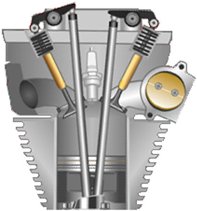 The intake valve (shown on the right in this illustration) is pushed down by a cam shaft, compressing the spring and opening the inlet port. The exact arrangement will be different from one engine design to the next. What is fixed is the movement of the valve itself and that movement only takes place every second revolution. There are various ways of using those movement to eliminate the waste spark and retard the timing. If a switch were mounted so that it opens when the intake valve opens and closes when the intake valve closes, then the switch closure shows when the piston starts upwards on its compression stroke and a simple electronic circuit can then give an adjustable delay before firing the coil which produces the spark. This, of course, involves disconnecting the original electrical circuit so that no waste spark is generated. The current flowing through the switch contacts can be arranged to be so low that there will be no sparking at the contacts when the circuit is broken again. The switch positioning might be like this: 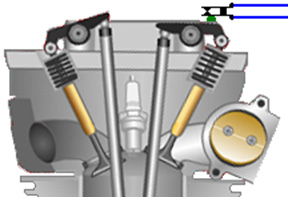 An alternative is to attach a strong permanent magnet to the rocker arm, using epoxy resin, and then position a solid state "Hall-effect" sensor so that it triggers the delay before the spark is generated. If the engine did not have a waste spark, then in theory, the timing mechanism of the engine could be used to retard the spark. However, in practice, the timing mechanism is almost never capable of retarding the spark to the position that is needed for running without fossil fuel, and so, some kind of delay circuit will be needed anyway. The sort of delay circuit needed is called a "monostable" as it has only one stable state. A basic circuit of that type is:  If you are not at all familiar with electronic circuits, then take a look at the beginner's electronics tutorial as that explains how circuitry works and how to build any simple circuit from scratch. We can use two of these circuits, the first to give the adjustable delay and the second to give a brief pulse to the ignition circuit to generate the spark:  Making the hydroxy gas When the generator is running, we have a ready supply of electrical energy, coming from a piece of equipment which has been specifically designed to supply large quantities of electricity for any required application. We are not dealing with the spare capacity of some low-grade alternator in a car, but we have substantial electrical power available. Having said that, the electrolysers described at the start of this document are efficient and it is unlikely that an excessive amount of power would be needed when using one of those designs. Another convenient factor is that this is a stationary application, so the size and weight of the electrolyser is not at all important, and this gives us further flexibility in our choices of dimensions. As this is an application where it is highly likely that the electrolyser will be operated for long periods unattended, an automated water supply system should be provided. The main details of such a system have already been covered, but what has not yet been dealt with is the switching for the water pump. The water pump itself can be an ordinary windscreen-washer pump, and we need some form of switch which operates on the electrolyte level inside the electrolyser. It is sufficient to sense the level in just one of the cells inside the electrolyser as the water usage will be pretty much the same in every cell. If you make the electrolyser in a suitable size or shape, then a simple off-the-shelf miniature float switch can be used. If you prefer, an electronic level sensor can be operated, using two bolts through the side of the electrolyser as the level sensor. A suitable circuit for this simple switching task could be:  When the electrolyte level inside the electrolyser is in contact with the upper bolt head, the circuit is switched off and the water pump is powered down. The electrolyte has a low resistance to current flow, which is not surprising as we went out of our way to make sure that it has, and so it is short-circuiting the ten thousand ohm variable resistor VR1, and dragging the voltage at point A down to a low value which keeps the three transistors TR1, TR2 and Tr3, switched off and the relay powered down. When the electrolyte level falls below the upper bolt head, the voltage at point A is no longer pinned down to a low value and it starts to rise. This rise is delayed by the capacitor C so that minor ripples on the surface of the electrolyte do not keep tripping the circuit on and off in rapid succession. After a few seconds have elapsed during which the electrolyte has stayed below the upper bolt head, the voltage at point A rises far enough to trigger the circuit. Transistors TR1 and Tr2 are wired together in such a way that they switch on suddenly and change transistor TR3 cleanly over from its Off state to its On state, powering the relay and starting the water pump. When the water pump adds enough water to the electrolyte to bring the level back up to the upper bolt head, the short-circuiting effect of the electrolyte pulls the voltage at point A back down again and switches the water pump off again. The big advantage of this arrangement is that the sensor inside the electrolyser has no moving parts and there is not the slightest chance of a spark occurring between the bolt heads. This circuit can be built in many different ways: using screw-connector strips, a printed circuit board, stripboard, etc. A possible physical layout for this circuit is shown here: The following layout is based on the standard 10-strip, 39-hole strip-board, the underside of which looks like this:  For convenience in drawing, the holes are represented as the points where the lines cross in the diagram shown here:  The horizontal lines represent the copper strips and the intersections with the vertical lines represents the matrix of holes. Many different layouts could be used for this circuit, so the following diagram is only a suggestion:   The water-level control for the water supply to the pond fogger or Venturi tube misting device does not need any form of fancy mechanism. The standard ball-cock valve mechanism which is used with toilets is quite adequate, especially if a floating pond fogger is being used as it maintains its own optimum depth below the surface and so the overall depth is not in any way critical provided, of course, there is sufficient depth for the fogger to float correctly. Starting: When left for any length of time, the gas pressure inside the electrolyser will drop because the nature of the hydroxy gas alters. This means that there will not be sufficient hydroxy gas available to start the engine and no more gas will be generated until the engine drives the generator. So, to deal with this situation, a lead-acid car battery is included so that it can be switched in to replace the generator for a brief period before the engine is started. That inclusion gives this overall arrangement:  This arrangement is perfectly capable of running a standard generator without the use of any fossil fuel. A generator run like this has almost no harmful emissions as the only possible contaminant is a minute amount of lubricating oil escaping past the piston rings and being burnt along with the hydroxy gas. It should be noted that while no fossil fuel needs to be bought to run this generator system, the electrical output is far from free and is actually quite expensive as there is the purchase cost of the generator, the electrolyser and the minor additional equipment. Also, generators have a definite working life and so will need to be refurbished or replaced. It might also be remarked that if a generator of this type is going to be used in an urban environment, then the addition of sound-reducing baffles and housing would be very desirable. At this point in time I am aware of five different electric generators which have been adapted to run on water. At least four of these are from different manufacturers. The method of altering the timing and dealing with the waste spark is different from one adaption to the next. One user has altered the spark timing of his generator to after Top Dead Centre by rotating the timing disc to a position not envisaged by the manufacturer. The timing disc is held in place by a locking ("key") bar which fits into a channel cut in the shaft of the engine, matching it to a similar channel cut in the disc. The alteration was achieved by cutting a new channel in the shaft, allowing the timing disc to be positioned further around the shaft, producing the required timing delay. This arrangement also makes the waste spark ineffective and so it can be ignored. While this method requires the cutting of a slot, it does away with the need for any electronics and it is a very simple solution. If you feel that the construction of a suitable electrolyser would be a problem or that the amount of electric current needed to operate it would be excessive, let me show you the actual figures involved: Michael Faraday was an exceptional and highly respected researcher who investigated the electric current needed to convert water into hydrogen gas and oxygen gas by electrolysis. His results are accepted by pretty much every scientist everywhere. While he expressed the results of his work in terms which would be meaningless to the average person, his result is that an electrical input of 2.34 watts produces one litre of hydroxy gas in one hour. In practical terms, that means that a current of 0.195 amps at 12 volts will produce 1 litre of hydroxy gas in one hour. In passing, only a nearly discharged lead-acid battery would have a voltage of 12 volts as the fully charged state is 12.85 volts and a vehicle alternator produces about 14 volts in order to charge the battery. It is easier then, to compare the gas output of electrolysers directly to the figures produced by Faraday as shown here, based on a gas output of 15 litres per minute which is 900 litres per hour: Faraday: 900 litres in one hour, takes 2,106 watts or 100% Faraday Boyce: 900 litres in one hour, takes 998 watts or 211% Faraday without pulsing Boyce: 900 litres in one hour, takes 180 watts or 1,170% Faraday with pulsing Cramton: 900 litres in one hour, takes 90 watts or 2,340% Faraday Much of this is not very important as it has been demonstrated that a gas production rate of around 3 lpm (180 lph) is sufficient to run a generator which produces 5,500 watts. Let us assume that the measured figure is 100% wrong and that it takes 360 lph of hydroxy gas, plus cold water fog, plus air, to run the generator, then: Faraday would need 843 watts Boyce would need 400 watts without pulsing Boyce would need 72 watts with pulsing Cramton would need 36 watts None of these figures are important for running a generator because with an electrolyser efficiency of only 50% Faraday still leaves a massive generator excess of nearly 4 kilowatts on a 5.5 kilowatt generator. The gain is in running a generator as an internal combustion steam engine and not in the great efficiency of the electrolyser. It is distinctly possible that the pessimistic figures shown above are twice what is actually needed, but who cares? - the facts speak for themselves, with several people scattered around the world, already running generators on water. Many different generator designs have been adapted, typically, by modifying the flywheel, filling in the keyway and cutting another one to give a spark 2 degrees after TDC. Experience has shown that the 6.6 kVA Honda V-twin petrol motor generator and the Vanguard V-twin work very well long-term when adapted to run on water only. Please Note: This document has been prepared for information purposes only and must not be construed as an encouragement to build any new device nor to adapt any existing device. If you undertake any kind of construction work, then you do so entirely at your own risk. You, and only you, are responsible for your own actions. This document must not be seen as an endorsement of this kind of generator adaption nor as providing any kind of guarantee that an adaption of this kind would work for you personally. This document merely describes what has been achieved by other people and you must not consider it as being a foolproof blueprint for replication by anyone else. Peter Lowrie of New Zealand developed an electrolysis system for use with internal combustion engines. Like the previous systems, Peter feeds a spray of fine water droplets into the engine, using a carburettor, supplied by a water tank. He also feeds in some exhaust gas and heated hydroxy gas, which is a technique which is almost identical to Stan Meyer's method. Peter also produces a very large volume of hydroxy gas with a most unusual method. He uses a delta-wound, GEC marine alternator (though he says that the alternator from a truck would do). He modifies the alternator by removing the diodes inside it and leading each of the three phase-windings out to his electronics. He uses each of the three phase-windings to power one electrolysis cell. He applies only 2 volts or so, to the DC winding of the alternator, which is about the minimum which allows the alternator to work. The DC current supplied is less than one amp while the pulsed current to the electrolysis cells is much higher. When a snap-on ammeter surrounds the wires to the cells, a current of at least 800 amps is displayed. A point of particular interest is the inductor (coil) placed between the electrolysis cells and the windings of the alternator. Peter describes this as a choke out of a 3-phase industrial power supply. It is comprised of a laminated steel core with a sheet of copper wound around it. This is remarkably like the arrangement used by Stan Meyer and already described earlier in this document. Peter has run a 1,600 cc car engine at 5,500 rpm with the gas output from his cells. He believes that his method of cascading the gas output from the cells through each other, produces a more active form of hydroxy gas. He also uses a heat-exchanger which allows the exhaust to pre-heat the hydroxy gas before it is passed to the engine (a method also used by Stan Meyer for running a car on water alone). Peter also uses impulse-operated valves to control the flow of gas to the engine as shown here:  The use of water in engines. I can fully understand someone having difficulty with accepting the idea that water can be used as part of the fuel inside an internal combustion engine. However, there is an old saying that "fact is stranger than fiction" and that certainly appears to apply in this case. First, it is essential to accept the fact that it can be an important component inside the engine, as this has been demonstrated by several different people who do not know each other and who live in different countries around the world. Second, having accepted that fact, the next step is to ask what exactly happens with the water. I have come across an interesting document dated May 2009. I have been unable to trace its origin in order to ask permission to reproduce it here, so if you know how to contact the author, then please let me know. This is a report on an actual experimental tests on an internal combustion engine: Ambient heat into work conversion. Water-steam car, simple concept: simple Otto engine running from water mist using standard off-the-shelf ultrasonic humidifier (4 stroke diesel engine will work as well...could even perform better). Replication log: Ultrasonic humidifier 0.25 litter water vaporisation per hour was set to 1/3 of its power. Use the water humidifier at air intake. Remove carburettor (or injection stuff if any) and filter for first. The way from duster to the engines air intake should be as short as possible to avoid the micro water droplets created by the humidifier collecting on the inside of the tube which feeds the water mist to the engine air intake. The engine used was a 1-cylinder 200 cc electrical generator. The engine ran very slowly at first. In the case of a 4-stroke Otto engine, it is possible to speed it up using a propane cartridge. The engine then tends to "lock" into a higher rpm band, where the propane can be cut off permanently. The air going into the engine has a temperature of 22° C, while on average the air temperature leaving the engine was -16° C ( a 38° C drop). This is amazing – but this concept really does work! You can make the car engine idle using this method. The water may need to be a bit warm. Ignition is not needed but it does facilitate the engine running. You may need to “turn the key” several times (based on this replication test). In the case of a diesel engine, you may need to replace the injectors with some kind of spark plug like on an A.E.R.O.P.S engine or use Firestorm plugs or any other stuff which is able to give the water an additional blast via plasma discharge, to increase performance further. You can make a gasoline generator work with water steam, also a lawn mower, etc. Now – when it idles you have gone ‘over the edge’ so you need to add some more power, possible options are: adding hydrogen or HHO, preheating the water (possibly with solar energy), adding some fuel or spirit, powerful ignition or maybe some magnetic polarisation. This concept is now public and you can experiment with it on your own. Follow safety precautions and use common sense. Do not expect high rpm results on the very first test run. Its a very basic concept which shows just one kind of transformation of environment heat into pressure and usable work. Also, do not pre-heat the engine before using it. The engine must not be hot! A bit of physical background: During the first stroke of a 4-stroke Otto engine, the piston moves down and sucks ambient air into the cylinder. During the second stroke, the piston moves up and compresses this air to a pressure of 25 bar (atmospheres). According to the “ideal gas law”: the temperature rises due to compression above its initial ambient temperature. The compression ratio of the engine will boost the temperature, typically up to 450°C to 500°C. This second stroke of an Otto engine NEEDS ENERGY FOR COMPRESSION! Now consider what will happen to microscopic water droplets contained in the air inside the cylinder. If the water converts instantly to flash-steam, then its volume increases dramatically, boosting the pressure inside the cylinder and powering the piston during its power stroke and storing energy in the flywheel. Please note, that the water mist isn’t water vapour...it’s not a gas! It is still a liquid! The important DIFFERENCE becomes evident during the compression stroke! As the piston starts to move upwards to compress air which contains the water droplets, pressure AND HEAT, as described before, start to rise. BUT the compression itself is NOT able to raise the water temperature directly, as the water is still a LIQUID and therefore the temperature of the water isn’t affected from higher pressure! So initially, only the air temperature rises due to compression. But tiny water droplets are present inside the cylinder, and as the air temperature gets greater and greater than the temperature of the water droplets, heat starts to flow from the air into the water droplets, heating them up! But as long the water temperature does not reach its boiling point, the droplets will not expand due to this rise in temperature and they will simply keep the same volume. So the water droplets acting as a heat-absorber during the compression stroke! Lower heat implies lower pressure, and lower pressure during the compression stroke implies ENERGY SAVING DURING THE COMPRESSION STROKE! Please have a look at the following graph (no losses are included in the calculation): The graph shows the pressure within a 4-stroke engine cylinder in respect of time, starting from the beginning of the compression stroke (second one), ending with the end of the power stroke (third one). The work that is needed for the compression stroke is represented by the integral of the graph, from the very left to the yellow marker. The work which is done by the piston during the power stroke is represented by the integral of the graph from the yellow marker to the very right of the graph (20,000 at the time scale). Let's assume that engine is an ideal one (loss-less). The red graph line represents the pressure within engine cylinder, if no water is present, and no ignition occurs. The graph is symmetrical to the Top Dead Centre (the yellow marker in the middle), so we put in energy at compression and we get the same amount back during the 3 stroke (power stroke). No loss, no gain. We get plus and minus zero. The blue graph line shows what happens, if microscopic water droplets are present. The pressure does not rise as much as in case without water droplets, because the water works as a heat absorber during the compression stroke, and this lowers the pressure as well. The shape of the graph changes, so that symmetry of the compression and power strokes isn’t there any longer, resulting in a gain of energy. Factors which affect this process include the water droplet diameters, droplet distribution, the engine's rpm which controls the length of time, the ambient air temperature, the engine's compression ratio and even the water hardness and it's physical properties. It is certainly not a simple case where you can say “more water, means higher revs giving more power”. For example, if the water droplets are too large, then there will be too little conversion to steam and insufficient power will be produced. Alternatively, if there are too few water droplets, then there may ne no effect at all or the conversion to steam may take place too early to provide useful power. The theory given here is a very simplified one, but should suffice for the first steps towards a better technology and a better understanding of the concepts of “energy from the environment”. It is tempting to conclude that the power gained from water droplets inside an engine cylinder are caused by the water turning into flash-steam and nothing else. However, that is probably not the case, nor is it the case that energy placed in the water by the sun heating it is extracted (which does happen) and that is the only additional source of energy. In the scientific paper entitled "Possibility of Liberating Solar Energy via Water Arc Explosions" by George Hathaway and Peter Graneau, they discovered that when they produced an electric arc discharge in cold water fog: "The principal discovery made in the past two years was that it is a collection of fog droplets in the water which explodes and not the liquid water itself. The term 'fog' is meant to include not only the tiny droplets which float in air but also larger droplets which fall in the atmosphere and would be more correctly described as 'mist'. The sole explanation of the explosions so far put forward contends that the intermolecular bonding energy in fog is less than 540 callg, the latent heat of bulk water. The bonding energy difference is then liberated in a quantum jump when the fog is formed in micro-seconds". Summing up their experiments, they conclude that "virtually all the kinetic energy developed by the explosion must be internal water energy" In the earlier scientific paper "The Anomalous Strength of Cold Fog Explosions Caused by High-Current Water Arcs" by N. Graneau, he comments: "The unusual strength of explosions caused by a pulsed current flowing through water plasma was first noticed in 1907 by Trowbridge in his early high-voltage laboratory at Harvard University. When he passed as arc through a spray of water, the resulting explosion was louder than in ordinary laboratory air. During the Second World War, Frungel measured the strength of water arc explosions and published his results in 1948. He concluded that they were not caused by heat and steam and freely admitted that he was unable to explain the phenomenon. In 1969, the US Bureau of Mines issued a long report on their investigation into using water arc explosions for rock fragmentation. In one experiment, the investigators at the Twin City Mining Research Centre noticed that the energy output was apparently 156% of the input. This result was reported but treated as an experimental error". The bottom line appears to be that using cold water mist droplets in an internal combustion engine has a minimum of the following energy additions:
5. Other Useful Devices The Vortex Air-feed system Ted Ewert has developed and tested a very effective and simple device which can improve the running of some vehicles. This device works best with four-cylinder vehicles because the pulsed air intake of vehicles with fewer cylinders, enhances the beneficial effect. This is a silent, simple and cheap device which enhances the airflow into the engine. This can have a dramatic effect on the performance of the engine. For example, Ted has an old Datsun 310 which has been sitting unused for years. Gasoline loses it’s lighter fractions in six months or so and that makes it far less volatile and more difficult to burn. Ted’s Datsun has gasoline in the tank which is five years old and the car will not run on that fuel with it’s normal air intake. However, when Ted put one of his turbines on it, it starts immediately and runs fine with that old fuel. That particular vortex turbine has been dubbed "The Respirator". The Datsun has a carburettor which shows that this turbine works well with carburettors. 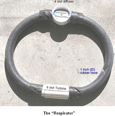 This simple device is a vortex tube made from a short piece of PVC pipe which has been slotted and shaped. It fits between the air filter and throttle body, or carburettor, and causes the incoming air to spin at a relatively high rate, creating a vortex. Angular velocity is crucial in the formation of a strong vortex and the air entering the Respirator from the air filter, arrives at right angles to the turbine slots, giving an immediate and powerful spin inside the tubing. Ted says: “Most people think of a spinning air mass as having no particularly unusual properties. This is not correct. A spinning air mass has some very unique and useful properties. Standard aerodynamics, and linear Newtonian physics are unable to explain the properties of a flow of air spinning at high speed. In fact, when compared to a static flow of air within a pipe, a vortex behaves in almost completely the opposite way. All spinning objects, whether they are solid, liquid or gaseous, contain two opposing forces: centrifugal and centripetal. Centrifugal is the expanding force travelling away from the centre axis, and centripetal is the contracting force pulling in towards the centre. This concept of dual forces is key to understanding a vortex. "Modern" physics has decided that the centrifugal force doesn't exist and now refers to it as a ‘false’ or ‘phantom’ force. This illustrates how detached from the real world academia has become and why it has stagnated. The combination of these two forces, acting together in a vortex, create some unique conditions. One of these conditions is a laminar configuration. Co-axial laminations form throughout the vortex, creating numerous layers of air spinning virtually independently of each other. These layers are separated by zones of extremely low, virtually zero, friction and this allows them to spin at different rates. As the vortex spins faster, the two opposing forces become stronger. This further laminates the flow as well as compressing the layers. The low-friction zones allow the compressed central air mass an unimpeded pathway for it’s axial flow through the pipe. This is the reverse of the flow conditions for a straight, non-coherent air mass which has a tendency to develop friction and resistance, due to turbulence, in direct proportion to its velocity through a pipe. Spin rate determines the degree of air compression and the linear flow rate of the mass. The faster that the vortex spins, the more it does just what we want, which is to create a dense, compressed and fast-moving flow. This is why we take the flow of air from the air box and use its speed and direction (90 degrees) to initiate the spin in our tube. This is by far the simplest and most efficient way to get the air spinning fast. The properties of a vortex are increased in step with the angular velocity. Just as a top wobbles and falls when spun slowly, so a vortex will not exhibit any strong properties until spun really fast. As you may know, an important part of supplying air to an engine is the ability to supply a lot of air in a short burst. This turbine creates a spinning air mass which is uniquely able to supply this air due to its virtually frictionless laminar composition and pressure built up through compression. The vortex provides compressed, dense air to the cylinder, which takes significantly less energy to draw in due to it’s stored inertial energy, and it’s ability to move freely in the direction of it’s axis of rotation. Between engine cycles, when air is not needed, the vortex continues to spin and build up additional pressure. This spinning air mass acts like a flywheel and stores energy which is put to use on the next intake stroke. A static air flow has no such stored energy and has to be accelerated by the engine intake stroke every time air is needed, thereby wasting energy. This flywheel property is key to understanding why the vortex works as well as it does. Unless the vortex is pulsed, or modulated, no extra energy can be developed. In a multi-cylinder car the flow of air becomes so steady that no effect is produced with just the turbine because there is no pulsing in the airflow into the engine. The rapidly rotating air within the turbine acts as a flywheel. When it is pulsed by the cylinder on the intake stroke, force is applied to the vortex as air is sucked down the pipe and into the cylinder. As soon as the intake valve closes, the pulse ends, the air stops its linear movement, but increases it's angular spin velocity. This is where the extra power is generated. While the intake valve is closed, the vortex continues to draw more air into the pipe, where it is accelerated and compressed, until the intake valve opens again. Power cannot be accessed until the pulse ceases. In a steady flow this never happens. Force has to be alternately applied and relaxed. To help visualise this imagine a coil spring attached to a shaft. When a sharp pulse is applied to the shaft, the spring expands. Only when the pulse ceases, and the spring starts to contract does the power get translated into movement. This also applies to a flywheel. You can also see with the coiled spring that the pulse must be timed to coincide with the resonant frequency of the spring for the highest efficiency. Random pulses, or pulses that are badly timed, will not have nearly the effect that correctly timed pulses have. The air turbine doesn't rely as much on resonance as it does on large, well spaced pulses. This is because the power of the pulse is huge in comparison to the inertia of the air. Resonance is essential for anything that has a fair amount of mass - solids or liquids. In the case of a multi-cylinder engine, the pulses become less distinct the greater the number of cylinders. A six-cylinder vehicle barely sees any gain from the turbine, and an eight-cylinder little to none. With this type of engine the vortex needs to be modulated to gain energy. This enhancement can be done through manipulating the shape of the intake tube. A round tube gives no gain but if the tube is "egg shaped" it produces an alternate centripetal / centrifugal pulse which imparts extra energy to the vortex. Just as the Earth draws energy from it's elliptical orbit, so in the same way, the vortex gains energy with each rotation it makes through an elliptical, or egg shaped tube. I put a slice of a smaller diameter pipe along the inner top of my tube. This small addition accomplished a noticeable increase in performance for the unit in my car. A curve in the pipe will also act like an ellipse since the rotation is compressed on the inside of the curve and expanded around the outside. Another interesting thing with the turbine is that it works much better when the engine gets hot. I notice a large increase in power in my bike as soon as the engine gets hot. This is because the heat adds energy to the vortex, just like a hurricane travelling across warm water. The heat added by the intake tube adds velocity and compression to the vortex as it spins waiting for the intake valve to open”. 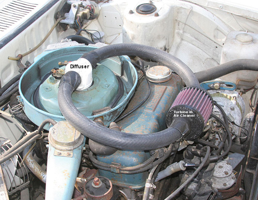 The vortex is created by cutting angled slots into a piece of PVC piping as shown here:  The air enters through each of six tapered slots cut parallel to the axis of the pipe. These give the air an initial spin inside the pipe and the pulsating intake of the engine, combined with the oval shape of the PVC exit T-piece, accelerates the air into a serious vortex which improves the intake to the engine, raising it’s efficiency and giving more engine power.  Ted created the egg-shaped part of the final PVC T-piece by adding an extra cut section of PVC pipe to a standard T-piece as shown here:  The turbine which Ted put on his bike works outstandingly well. The torque curve is extended well below it's former efficiency range. It is possible to substantially enrich the fuel / air ratio and still maintain the same mpg results as before. When the turbine is removed, both the mpg and the engine performance go way down. The turbine adds more air to the engine. To take full advantage of the possible increase in performance, the mixture should to be enriched. Ted also put one in his 1995 Toyota Corolla car which has an 1800 cc 4 cylinder engine and a 5 speed gearbox and he is getting over 40 mpg on the open road and the low 30s around town. Originally, those figures were 34 on the open road and 27 around town. The performance has also increased very noticeably. Another nice feature is the lack of knocking and pinging under load. Performance in the mountains at high altitude is also significantly improved. Ted has spent only a couple of months testing and evaluating this device on his cars and bike. A problem with this device is that it cannot be run directly through a carburettor, as it can with a fuel injection system. A carburettor works with a venturi which develops a low pressure zone in the throat with respect to the float bowl pressure. A vortex has no respect for a venturi and creates it's own pressure gradient which screws up the fuel metering. Ted has somewhat solved this issue by diffusing the vortex just before it enters the carburettor. Pressure and velocity are built up before the carb then sent through a diffuser. There is still plenty of research to do with this device. And there will be many improvements and beneficial modifications still to be made to it. Ted remarks that he does not have access to any engine test facilities and that makes it difficult for him to assess accurately the results of any design variations which he may make. Ted is hoping that someone will take his design and improve it further. There is great potential in this little piece of plastic pipe. Ted has fitted a different style of his turbine to his Toyota as shown here. The turbine section is marked “PMT” which stands for “Poor Man’s Turbo”, though obviously, you don’t need to be poor to benefit from a turbine system like this which has no moving parts:  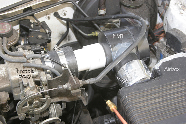 Cam Timing A deceptively simple way of improving mpg performance has been discussed recently in the watercar forums, and that is the adjustment of the cam settings on American cars made since 1971. This sounds most unlikely, but it is a proven fact. For example, a 2004 Jeep Wrangler 2.4 litre received a 10 degree advancement on both cams, and that gave a 70% improvement on the mpg, much more engine power and an exhaust which runs much cooler. Over the years, one man experienced a 50% to 100% improvement in mpg over a range of personally owned cars and trucks, and the emissions were improved by nearly 90%. It is not suggested that everybody should make a cam adjustment, just to be aware that an adjustment of that nature can have a dramatic effect. Another example: “Advancing the cam timing will make the engine run cooler. I have been messing with cam timing for about 25 years. I had a 1985 Ford Ranger with a 2.8 litre engine - it was a dog. The same engine used in the 1970 Mercury Capri had lots of power. The Ranger was a dog because the cam timing was set almost 10 degrees retarded. I gave it an 8 degree advance and the Ford Ranger came to life and hauled ass. Also, after-market ratio-rocker arms help a lot on late model cars. I changed the cam timing on my 1998 Chevy truck by 10 degrees. With it’s 350 cubic inch engine and ratio rocker arms installed, it gained almost 90 horsepower and brought the power band lower giving more torque because the rocker makes the cam have higher lift and longer duration on the cam which makes it breath better.” Comment from a man with 25 years experience in this field: “Cam timing is when the valves open and close in relation to the crank shaft and piston movement. The number 1 piston is set at true Top Dead Centre. At this point the degree wheel is set to the front of the engine against the front pulley at the zero degrees mark and you install a pointer mounted to the engine block pointing at the zero mark on the wheel. When the crank is turned to about the 108 to 112 degree mark, the intake valve is fully opened. That is where most engines are set nowadays. This what I call retarded cam timing. The engine seems to run well but doesn't really to seem to have much low and mid-range pulling power. When racing, you would retard a cam for high RPMs, they also could breath and had no restriction in the exhaust. The power may come in at, lets say, 3000 - 6500 RPM and advancing a cam for more torque and power, that same cam may produce power at 1000 - 4000 RPM and after all, who drives over 4000 rpm on the road?” Another comment: “Our jeep has twin overhead cams. Advancing them does not make them stay open longer, they just open and close sooner. My reason for advancing both cams was, if I only advance the intake cam, the intake would open earlier causing more overlap if the exhaust wasn't advanced. Normally the intake valve closes after Bottom Dead Centre. Just by looking at the piston, sometimes it's almost one quarter of the way up on the compressing stroke before the intake closes. By advancing the cams, the intake closes closer to BDC. This produces higher compression. Years ago, when I did this to some of the V8s, I would switch to adjustable rocker arms and a solid lifter cam. I was able to adjust the overlap by backing off on the rockers. On an engine with one cam, advancing the cam will adjust both the intake and the exhaust. Rule of thumb is: lets say most engines are retarded by 4 degrees or more, you really don't want to advance the cams more than 4 degrees advanced. I sometimes push this as far as 6 degrees advanced for improved mpg. That is a total difference of 10 degrees from 4 degrees retarded to 6 degrees advanced. This works well with low compression engines. I also don't see a need to go to a higher compression ratio. Think about it: if you had a compression ratio of 12 to 1 and the intake closes a quarter of the way up the compression stroke, how much is compression will there be, compared to a 8 to 1 compression ratio where the full stroke compresses the mixture? If you had a engine that made it easy to get to the cam or cams by just removing a dust cover, like on our Jeep 4-cylinder, I would say to install adjustable timing gears. Then you could just remove the cover and play with the cam timing until you came up with the best power and mileage. The FireStorm Spark Plug: The “FireStorm” plug was developed by Robert Krupa and it is an innocuous looking spark plug which can be used to replace a standard spark plug in an ordinary production engine: 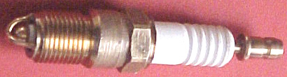 However, this plug is far from ordinary. The central electrode has been changed from a cylindrical post to a hemispherical dome, surrounded by four arched electrodes, each of which being positioned at a constant distance from the hemisphere. This allows a much greater spark area and results in very much improved performance. The fuel/air mixture can be made leaner without any harmful side effects. If this is done using standard plugs, then the engine will run at a much higher temperature which can damage the engine. But when using FireStorm plugs, a leaner fuel/air mix actually results in the engine running at a lower temperature. Robert has measured this effect and found that under identical running conditions, the engine exhaust was 100oF cooler when using FireStorm plugs. A mixture ratio of 24:1 is used rather than the current 14.7:1 mix and polluting emissions are very much reduced by the use of this plug design. Mixtures of up to 40:1 can be used with this plug. Robert has been awarded two patents for this plug design: US 5,936,332 on 10th August 1999 and US 6,060,822 on 9th May 2000. These show variations of the basic dual arch electrodes, two of which are shown here:  It was hoped that these plugs would go into production early in 2008 but there is no word of manufacturing starting. Robert gave Bosch of Germany a set of FireStorm plugs to test. After ten weeks of testing, their response was “This is unbelievable - we have never seen anything like this in all the time we have been building sparkplugs”. When standard spark plugs fire for a long time, the spark gap increases and the spark is weakened. Bosch ran an eight-week endurance test on the FireStorm plugs and found that there was zero gap growth. They concluded that FireStorm plugs would never wear out (which may well be why they are not yet in production - after all, who wants to manufacture something which never wears out?). Robert’s first FireStorm plug was made in 1996 and he has encountered strong opposition to their introduction and manufacture ever since. This plug will not be popular with the oil companies as less fuel is burnt. This is probably a fallacy because, human nature being what it is, people are likely to keep spending the same amount on fuel and just drive more. For the same reason, the plug will not be popular with governments who tax fuel. The companies who make spark plugs will not like it as it does not wear out like standard plugs do. It uses less fuel and cuts harmful emissions dramatically, so it will be popular with motorists and environmentalists, if Robert can get it into production. Water Vapour Injector System: Fifty years ago car engines were not nearly as powerful as they are now. In those says it was quite common for a driver to remark that his car ran smoother and more powerfully on wet days. This was not imagination as water vapour drawn into the engine along with the air, turned to steam at the moment of ignition, and expanding provided additional thrust to the pistons while lowering the running temperature slightly. This fact was utilised in World War II when units which were effective standard bubblers used with hydroxy boosters were added to the vehicles. Roger Maynard has built and used these units extensively since 1978, and my thanks goes to him for providing this information and illustrations. 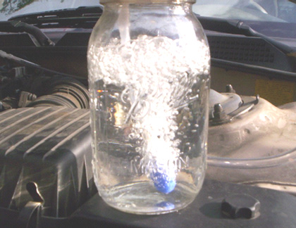 The unit is attached to the air intake of the vehicle, between the air filter and the engine. A small diameter plastic pipe is lead from there to a glass or plastic container holding water. In the above picture Roger is using a glass Mason jar with a screw-on metal lid which has a seal. Sometimes called a preserving jar, these jars are very convenient. The air feed into the jar is by a length of the same plastic piping and terminated with a standard air-stone or “soap-stone” as used in a home aquarium, as this causes a large number of separate bubbles. It is good practice to glue the plastic fittings to the lid of the jar, but this can make the jar too airtight and if that happens it may be necessary to remove the rubber seal which is around the neck of the jar. 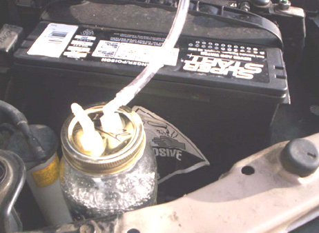 A glass jar has the advantage of not being affected by the heat produced by the engine. This is a very simple unit and it uses ordinary water which is not exactly a hazardous substance. The effect of using it is far greater than would be imagined. On Roger’s 4-cylinder KIA car, the mpg rose from 320 miles per tank full of fuel to 380 miles around town (18%) and 420 miles on the open road (31%) which is a very marked improvement. On his 6-cylinder Tacoma shows an 8% increase around town and a 12% increase on the open road. The water is topped up every 1200 miles or so. However, some engines are suited to the air-stone and some are not. Smaller engines may work much better if a stainless steel screw is used instead of the air-stone: 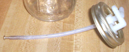 Just to clarify the operation of the device:  The container has a plastic elbow connection in the lid through which the outside air is drawn into the container. The air flows down through a plastic tube to either an air-stone from a pet shop, or a loose bolt in the end of the plastic tube. The air-stone has many small holes in it and these break the incoming air up into many streams of small bubbles. There is a second elbow in the lid and the air, which is now very damp, is drawn out through it by the reduced pressure in the normal air intake of the engine. The lower pressure there is caused by the intake strokes of the engine and the air going to the engine now comes from two sources – the normal path through the air filter, and the new path through the bubbler. Most of the air flows through the air filter as normal, but there is now a small percentage which flows through the water, adding cold moisture to the airflow. Some people feel that this couldn’t possibly make any difference, but experience has shown that the addition of this extra stream of damp air can and usually does have a beneficial effect, improving the mpg, making the engine run a little cooler and generally improving the operation of the engine. It is a very simple low-tech device which does not cost much, so if you feel inclined, then try it out and see what effect it has on your vehicle, after all, if it does not provide a useful improvement, then you can easily remove it. Fuelsavers: A similar system is on offer from the website where they offer small aluminium fins which mount on top of the trailing edge of the bodywork of a vehicle. The devices are reckoned to save some 10% to 12% on fuel consumption, they can be home-made, nine per vehicle is the recommended number. The device and mounting look like this:  The Ram Implosion Wing: The next device may not be a “free-energy” device as such, but if not, it is very close to being such. It is a structure, which when mounted on top of a motor vehicle, improves the airflow to such an extent that the fuel consumption is said to be reduced by a major factor. The device was invented by Robert Patterson and is said to create a vortex which not only decreases wind resistance but may also create a forward propulsion force.  It is claimed that the effect created by one of these wings reduces the amount of dust stirred up when driving along a dirt road and if there is a paper bag sitting in the middle of the road, it is left unmoved when the vehicle passes over it at high speed. About a dozen people are testing this device at the present time. The biggest effect is at speeds of 60 mph or more. One researcher states that he installed the wing on the roof of his Lincoln Town car using a roof rack which allowed the wing to hang over the rear window by some six inches. He states that his fuel consumption has improved from 17 mpg to 56 mpg. Positioning of the wing, texturing of the wing surface, and the speed of the vehicle appear to be important factors in gaining an improvement. There is a research group and the website is at: http://www.pureenergysystems.com/news/2005/03/08/6900067_RamWingUpdate/. High Mileage Carburettors. The very poor mpg figures produced by most US vehicles is a quite deliberate arrangement forced on drivers by the oil companies. In 1997, an engineer working at a US Ford company plant witnessed a 351 CID V8 started at about 4:30 pm. with a 1 litre bottle of fuel as an exactly measured amount. The next morning when he went to the factory floor, that engine was still running and had only consumed about one third of the one litre bottle. On asking about the fuel consumption, he was shown a display that read, "248.92 mpg". He was shocked and said, "This must be a mistake" but the engineer said that it was true. He then asked when they would have it ready to be put in a new Ford, he was told that he would not see it in his lifetime. This is company policy and has nothing to do with engineering which is easily capable of this level of performance. That 249 miles per US gallon is 298 miles per European gallon since the European gallon is 20% bigger than the US gallon. There have been more than 200 patents granted for high-mpg carburettors. These designs all give between 100 and 250 mpg on a US gallon of fuel. Not a single one of these designs has made it to the marketplace due to the fanatical opposition of the oil companies. Last year, the Shell oil company posted typical earnings for the year, which showed that that one (average) oil company made US $3,000,000 profit per hour for every hour of every day of the entire year. Did you enjoy contributing to that profit every time you bought fuel to burn? Nearly all of these high-mpg carburettor designs convert the fuel to vapour form before it enters the engine. There is no magic about this performance, just good engineering practice. It will probably come as a great surprise to you that the oil companies now put additives into the gasoline sold in the USA. They have 103 varieties of additives and they will explain that these are used to reduce evaporation in summer (as if they care about that !) and combat freezing in the winter. An “unfortunate” side effect of these additives is that they clog up any carburettor which converts the fuel to vapour form. Instead of 200 mpg, it is now quite common for US vehicles to have a 15 mpg performance and that effectively increases the cost per mile by more than ten times. I am confident that it would be possible to design a high-mpg carburettor which deals with the additive sludge left over when the fuel is converted to vapour. In passing, the present situation gives added encouragement to stop burning oil-based products and switch to electric, compressed air, or water-powered vehicles. That is a perfectly viable option technically, but it would create frantic opposition from the oil companies and most governments which raise massive revenues from taxing oil products. The energy problem is not technical, it is financial and political. I am not including details of any of these high-mpg carburettors in this chapter as they will be ineffective nowadays, but you will find nine of these high-mpg carburettor patents in the Appendix. Vortex Fuel Reforming This is a very important technology which has been around for more than a hundred years. The objective is to increase mpg not just by the vaporisation of the fuel but also by "cracking" the water / fuel mixture into smaller molecules before being fed into the engine. This is more advanced than the fuel ‘conversion-to-vapour’ technique of the high-mpg carburettors. To get a better understanding of this, you can try a Google search for "fuel reformer" or "steam reforming" which will provide additional information which may help you to understand the basic principles. The fuel-reforming method can be highly effective and its effectiveness has been proven beyond all doubt with designs from MIT, Philips Petroleum, Nissan Motors, NASA, universities and other very serious contributors. Some years ago MIT spent millions proving that on board fuel reformers would give us all better fuel economy and cleaner air. They did long-term testing on buses and cars to provide proof. They teamed up with the very large auto-parts supplier Arvin Meritor to put them in production vehicles. Then "One Equity Partners" bought out Arvin Meritor's division that did all the final work to get fuel reformers in all our vehicles. They created a new company, EMCON Technologies, and that company dropped the fuel reformer from their product line, not because it did not work but because it did work. There are various techniques for achieving this process. One which is easy to understand is shown here:  Here, the standard exhaust pipe is given a kink to move it clear of its normal run in order to allow an extra straight pipe of smaller diameter to be positioned inside it so that the hot exhaust gases are used to heat the incoming fuel flow. This is a useful energy gain as it uses some of the waste heat, raising the overall efficiency of the engine very considerably. This extra fuel-flow pipe has a solid magnetised ferromagnetic metal rod mounted inside it, blocking off most of the pipe area. This change in available flow area causes the fuel flow inside the pipe to speed up, and as well as that, it causes the flow to spiral around the rod in a vortex flow:  However, the magnetism of the solid rod, causes a most unusual effect and instead of the helical gas flow being as shown above, a highly uneven flow pattern is created. This causes the fuel flow to bunch up in the centre of the tube, generating a hot spot which creates quite unexpected results:  The really incredible result of this peculiar effect is that the fuel mix exiting from the tube, contains chemical components which did not enter the tube - impossible according to present day physics. This goes to demonstrate once again, that we really don’t yet understand the world in which we live. The fuel mix for use in this system is best provided by two tiny carburettors, one feeding a fine mist of water droplets and the other a fine mist of fuel droplets. These are fed directly into the intake of the fuel reformatter tube. These carburettors are of the miniature type used for radio control model aircraft and their venturi intakes are blanked off with a plate with a small hole in it. Air is not fed into the reforming tube – after all, this is a fuel reforming system. The air is mixed in with the reformatted fuel after it exits from the reformatter, as shown below. Some of the hot exhaust gas is fed into both of the carburettors in order to help prepare the mixture for the reformatting process. The blanking plates on the carburettors are there in order to reduce the amount of the exhaust gas being drawn in with the fuel:  The use of carburettors is important since using a bubbler as suggested in the free plans on the internet, creates problems as the lighter fractions of the fuel get taken first which is exactly what we don’t want to happen. The carburettors have the massive advantage that they feed all fractions of the fuel together and so the remaining fuel is always in the correct proportions. The ratio of water to fuel (typically gasoline or diesel) can be adjusted over a very wide range, with some people using 90% water. Actually, there have been claims of running on 100% water, using multiple reactors in parallel with energy being drawn either from transmutation of elements or perhaps spin interactions with the local environment. Jean Chambrin's patent give details of running only on water. There are several forums where members are researching and using various designs of fuel reformers, with the GEET designs being popular. The VortexHeatExchanger forum is one such research forum and one of the files there lists 214 different patents for these devices. There are several different types of reformer. Another forum is the GEET-Pantone forum.. Almost any hydrocarbon fuel can be used - vegetable oil, old motor oil, etc. the normal fuels are the most popular. A forum member named ‘bryishere’ says in a YouTube video comment: "Everyone should really try this. IT WORKS. I have spent a lot of time on this device. It's very simple. Just follow the plans and experiment as much as you can. Currently I am using 90% water and 10% crude oil/waste oil on a 1-ton, 1969 Chevy truck ....... Get out in your shop !!!!!" Video information on reforming can be found here and these devices are often used on stationary generators. These devices have been popular in France for some years now. Jean Chambrin found that the gases needed to swirl inside his reactor in the same direction that the crank was turning. There is a massive 175 Mb file called ‘FuelReformerTechnology.zip’ which you can search for and download from the internet if you are very enthusiastic. That file contains the contents of more than 220 patents and applications. These patents are also listed in the ‘Files’ section of the Yahoo VortexHeatExchanger forum mentioned above. The Weird Nature of Water This chapter has been dealing with systems for enhancing vehicle operation with the use of water, so it seems appropriate to finish it with a brief note on water itself. To a casual glance, it appears that we know all about water. It’s composition is H2O and when it breaks down, we get two hydrogen atoms and one oxygen atom - right? Well maybe, and maybe not. The longer you spend looking at systems which use water, the more you get to realise that water is by no means as simple as you might initially think. There is a much maligned branch of alternative medicine called “Homeopathy” which is based on giving patients very dilute water-based solutions various chemicals. Sceptical investigators have run professional-quality tests intended to show that homeopathy is fraudulent and has no medical benefits whatsoever. Unfortunately, the tests did not work out the way that the investigators wanted. The tests showed that there actually was some benefit from the treatments being examined, and unfortunately, because a placebo control group was being used, the placebo effect was definitely not the cause of the effects recorded during the trials. Determined not to just accept the results which went against their expectations, the testers started testing ever more dilute samples on the patients. They eventually got down to the level where there no longer remained a single atom of the chemical in the liquid being fed to the patients, but to their consternation, the medical effect remained. They tried water which had never had the chemical in it, and there was no medical effect. They returned to the apparently “pure” and definitely chemical-free water and the medical effect was seen again, in spite of the fact that there was not even one atom of the chemical remaining in the water. This showed clearly that the water was different after having had the chemical in it, even when no chemical remained. They were forced into the opinion that water has “memory”. That, of course, is a conclusion based on the facts which are hard to explain. You may wish to deduce something else from those facts, and that is entirely up to you - just be aware of the facts. Very interesting studies carried out by Mr Masaru Emoto here have shown that the thoughts of ordinary members of the public can alter the structure of water without there being any actual physical contact with the water. If the water receives positive thoughts and is then frozen, the resulting crystal structure will be like this:  While on the other hand, if negative thoughts are aimed at the water, whether just by looking at it and thinking, or by writing those thoughts down on paper, the resulting crystal shape is quite different when the water is frozen, as shown here:  It is not all that startling if you consider that the quantum mechanics researchers have been saying for a long time that experiments can be affected by the observer. People who build Joe Cells which operate through environmental energy focused by specially treated and structured pure water, record the fact that certain people can affect a Joe Cell in a negative way from a distance of fifty yards (or metres) away. Personally, I am quite sure that we do not understand the fundamental nature of our environment and that we have very little idea of how we as individuals impact on our surroundings. There is an extremely honest and reputable researcher called George Wiseman who operates through his company Eagle-Research (website). George is very experienced in producing “Brown’s Gas” and he publishes excellent instruction books on the subject. The really interesting thing is that Brown’s Gas is produced from water and that gas has the most remarkable properties which are not readily explained by our present day “conventional” science. When Brown’s Gas is used as the gas to power a cutting torch (like an oxy-acetylene torch) the resulting flame is nearly colourless and can be waved across a bare hand without any ill effects - the hand is not burnt. But when applied to a fire brick which is intended to resist high temperatures, it burns a neat hole through it. It will vaporise a tungsten rod which normally takes 6,000oC to do that, which indicates that the flame temperature depends on what it touches (!). It can also weld aluminium to aluminium without the need for an inert gas. It will weld aluminium to brass and it can weld a steel rod to an ordinary building brick. It can fuse glass to a building brick. This is not “normal” for a chemical combustion reaction, showing that Brown’s Gas is not a “normal” chemical substance. As Brown’s Gas comes from water, does that perhaps suggest that water is not a “normal” chemical substance? I will leave you to make up your own mind about that. Patrick Kelly engpjk@yahoo.co.uk http://www.free-energy-info.co.uk/ |